11. Input devices
For this week’s assignment, we looked at Input Devices .This week looked at the following:
Group assignment:
-
Probe an input device(s)’s analog and digital signals.
-
Document your work on the group work page and reflect on your individual page what you learned
-
Group ProjectLink
Individual assignment:
- Measure something: add a sensor to a microcontroller board that you have designed and read it
Group Assignment Reflection
This week saw my us looking at various input devices which are used to connect the physical with the digital world. Input devices can be looked at as the electonic representation of our senses. Digital input devices create digital signal (1,0) whereas analog input devices collect continuous data such as potentiometers, temperature sensor and light sensors . Therefore an analog to digital converter is used to convert continuous analog data into digital values.
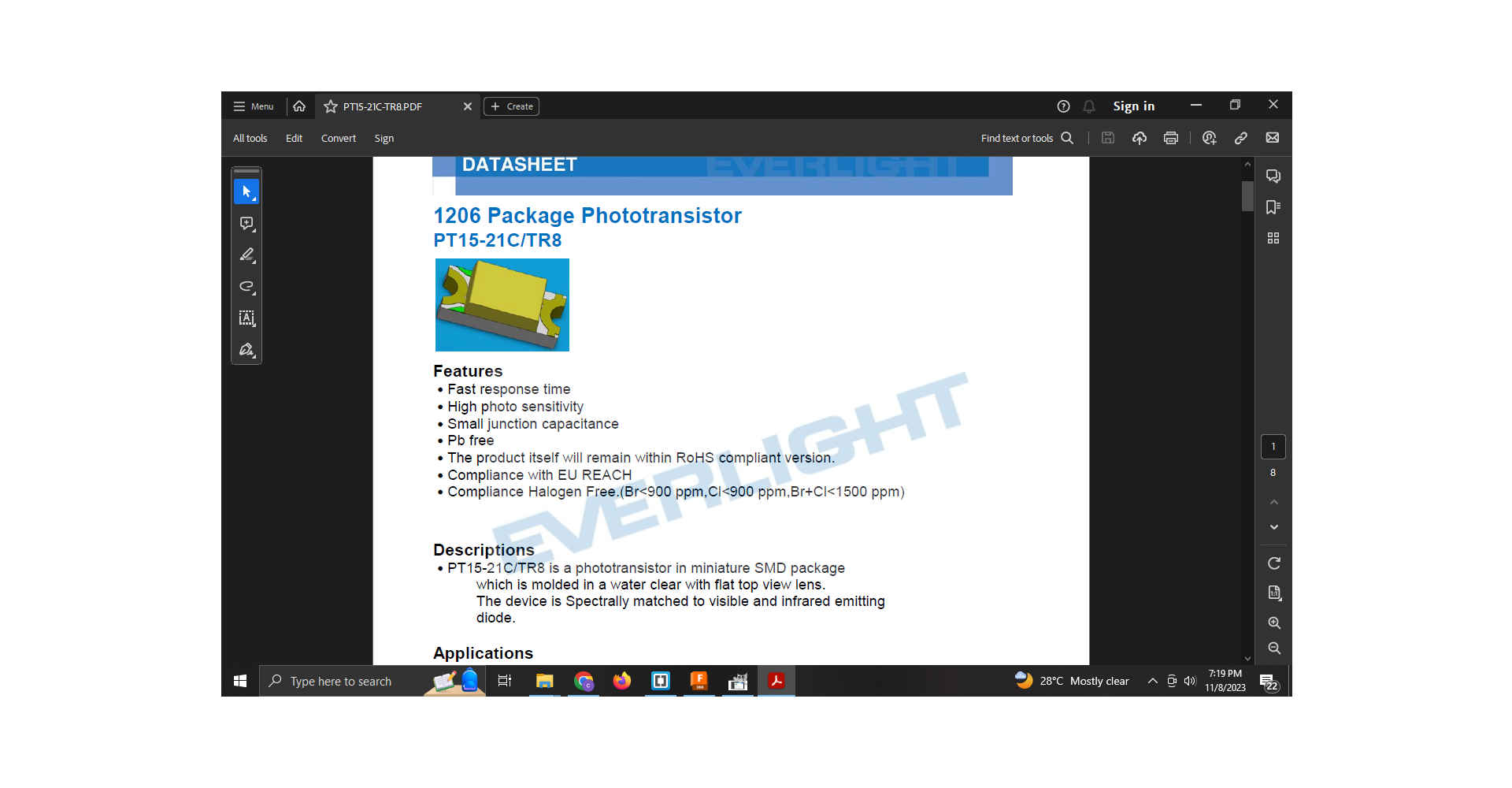
For this week my input device was a phototransistor as my final project dealt with solar tracking.A phototranisitor/photodetector is a device which respond to light or electromagnetic radiation.

1.As I had already created a micro-controller board for the electronic production week which can in corporate an input. I decided to build the board for my input device.
2.I opened Fusion 360 and started a new electronics design .
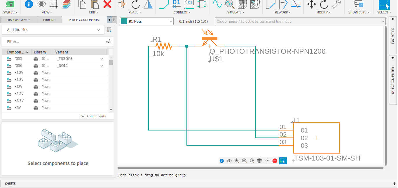
NB As this board did not require a microcontroller it had less components.
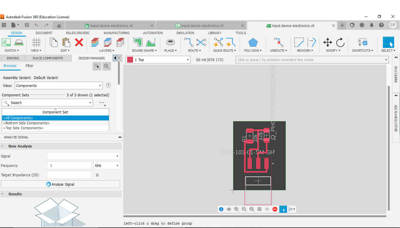
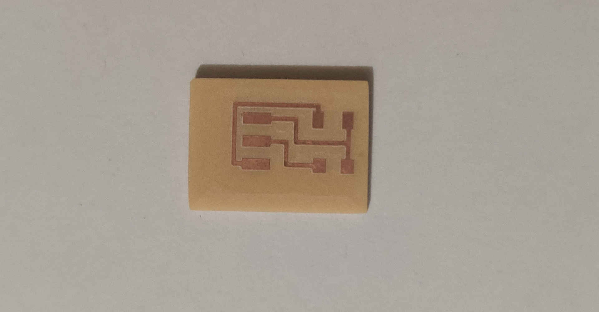
3.After the schematic was completed I ran the traces for the circuit.
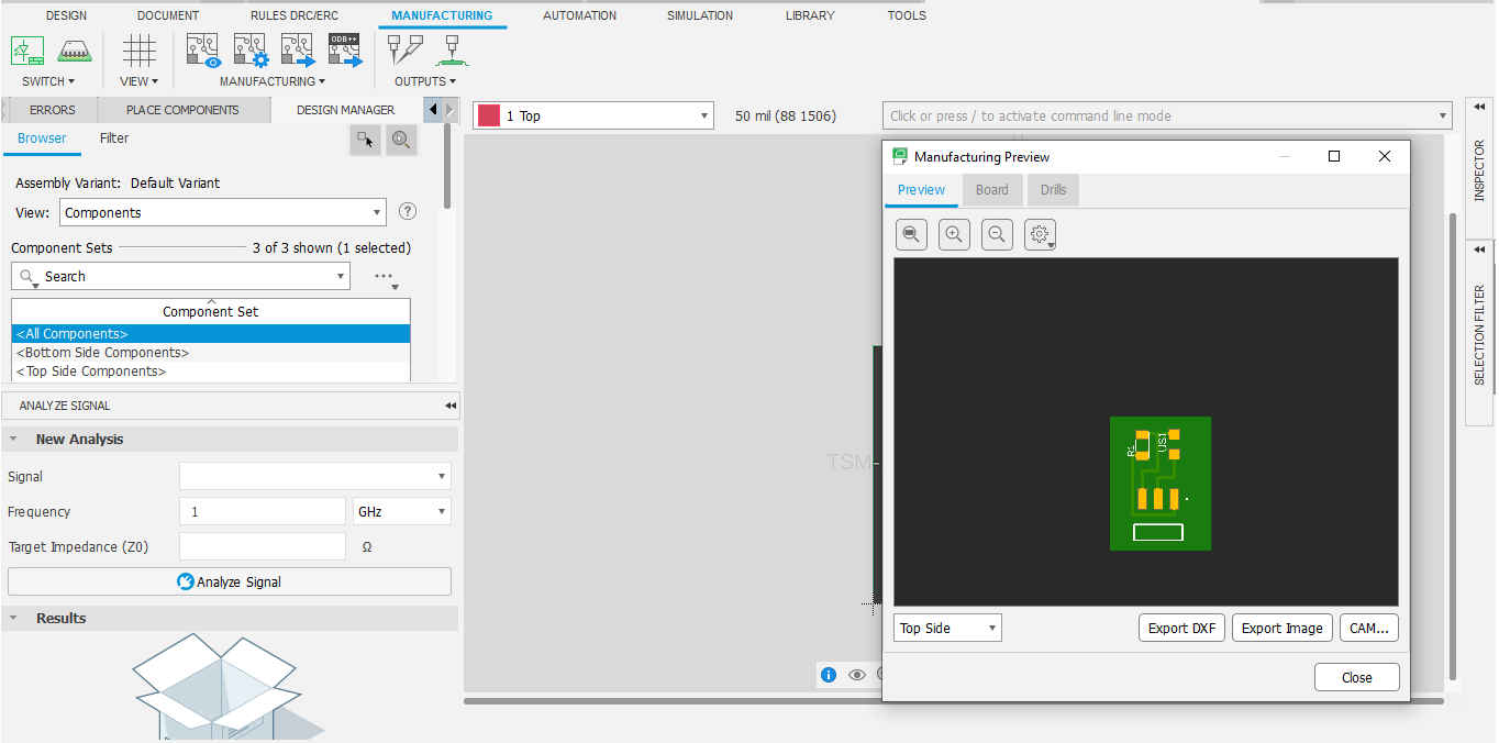
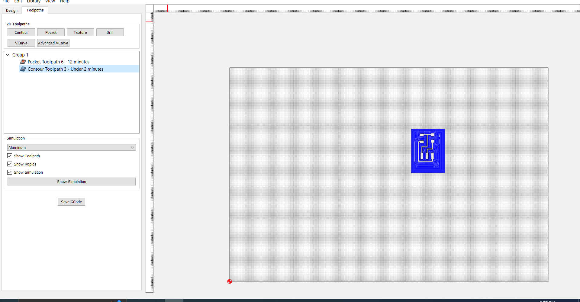
4.Then I exported the file as a dxf and opened it in Carbide Create to prepare it to be milled.
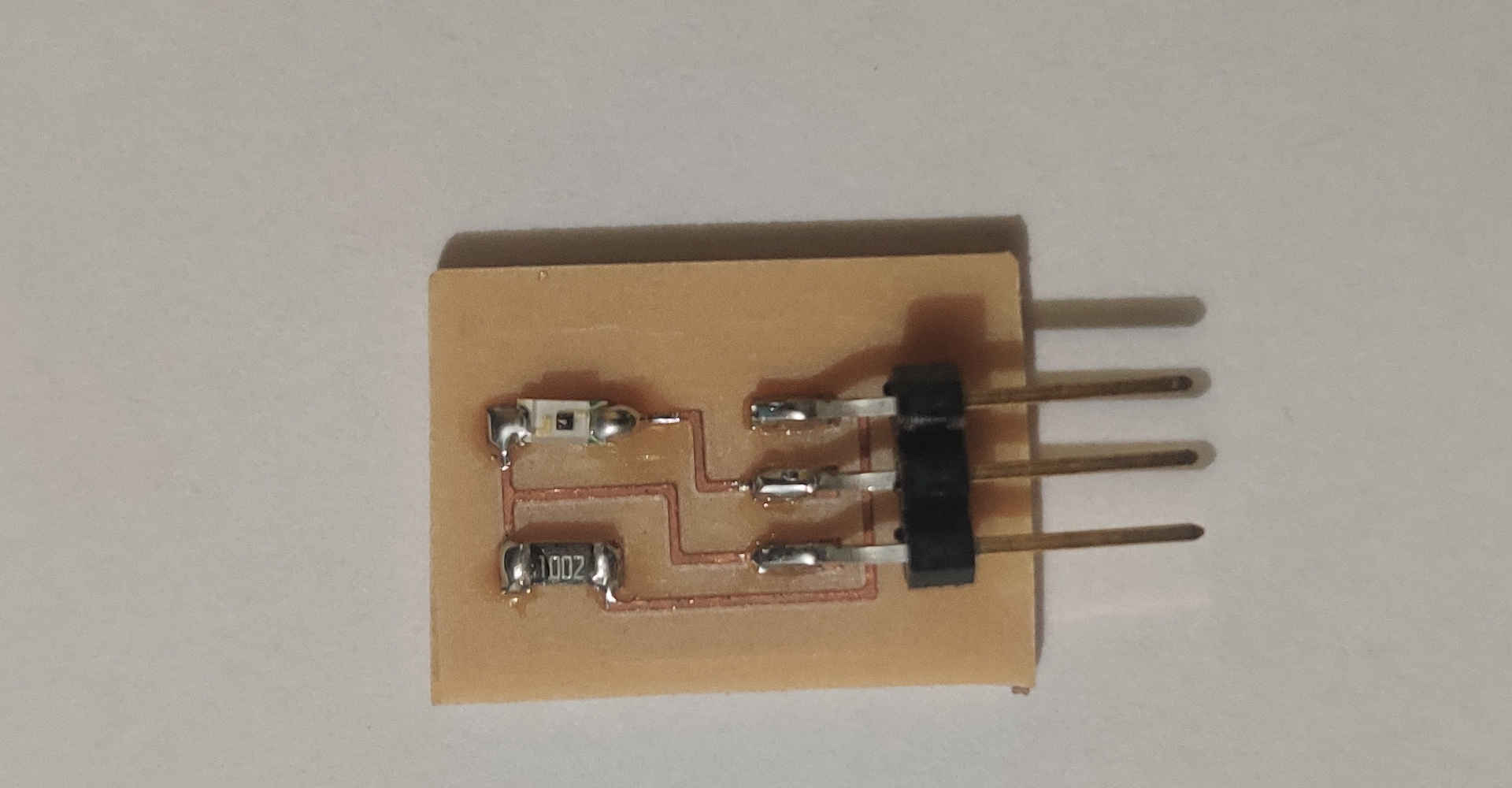
5.After the board was milled I soldered the components.
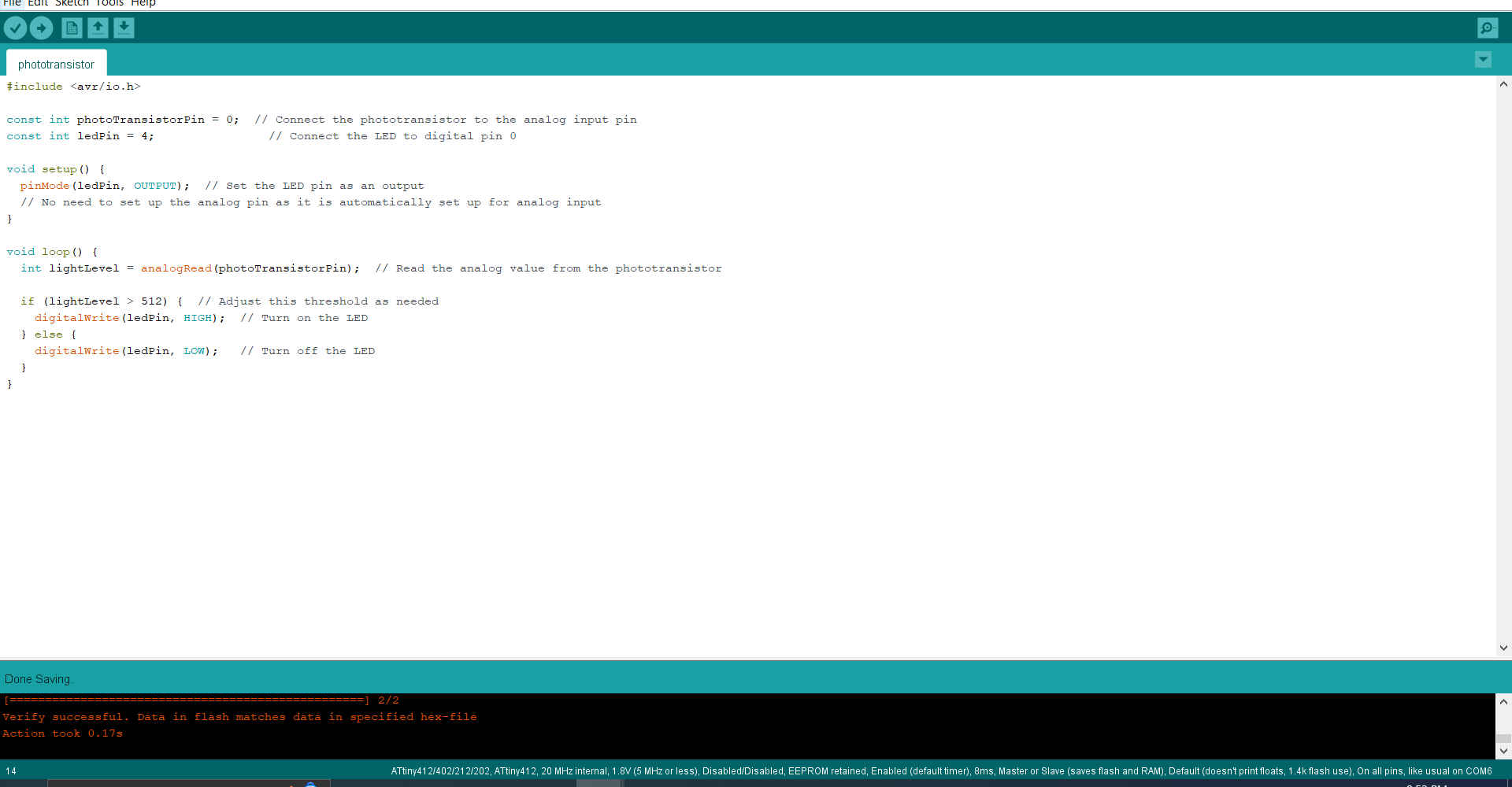
6.Then after looking at a few projects in Fab Academy and some online tutorials. I went to the arduino ide to write my code.
#include <avr/io.h>

const int photoTransistorPin = 0;  // Digital pin Phototransisitor is connected
const int ledPin = 4;                // Digital pin LED is connected

void setup() {
  pinMode(ledPin, OUTPUT);  // Set the LED pin as an output
  // No need to set up the analog pin as it is automatically set up for analog input
}

void loop() {
  int lightLevel = analogRead(photoTransistorPin);  // Read the analog value from the phototransistor

  if (lightLevel > 512) {  // Adjust this threshold as needed
    digitalWrite(ledPin, HIGH);  // Turn on the LED
  } else {
    digitalWrite(ledPin, LOW);   // Turn off the LED
  }
}
7.Then I uploaded the code to the microcontroller and tested it.
Download Files
Useful Links
DigiKey Phototransistor application