

Probe an input device's analog levels and digital signals
Link to Group AssignmentMeasure something: add a sensor to a microcontroller board that you have designed and read it
Assignment Requirement
Status
Linked to the group assignment page
Completed
Documented what you learned from interfacing an input device(s) to your microcontroller and how the physical property relates to the measured results.
Completed
Documented your design and fabrication process or linked to the board you made in a previous assignment.
Completed
Explained the programming process/es you used.
Completed
Explained any problems you encountered and how you fixed them.
Completed
Included original design files and source code.
Completed
Included a ‘hero shot’ of your board.
Completed
An input device is used to send a signal or data to a microcontroller which is then processed as instructions that can probably be used to control and output device. An input device can be as simple as a switch or more complex as a sensor.
For this assignment I made a sensor that uses the step response process. For this process I reviewed Robert Hart's Tutorial and I followed some of the procedures done by Adrian Torres and Pedro Chana. The step response is also the key process I will be using in my final project.
Step Response works by using two electrodes, a transmitter and a reciever. The reciever electrode is connected to an analog input and also to a pull-up and a pull-down resistor. These resistors also form a voltage divider and must be a high value of 1M Ohm or more. The transmitter electrode sends electrical field that varies in steps between high and low signls. This signal is recieved by the analog reviever to process. At any point of these steps, readings can be used for different purposes, in this case, the difference between the high and low will be taken using multiple samples.
The field signal will vary based on material and distance between electrodes and also size. Even a hand or other objects will affect the signal readings.
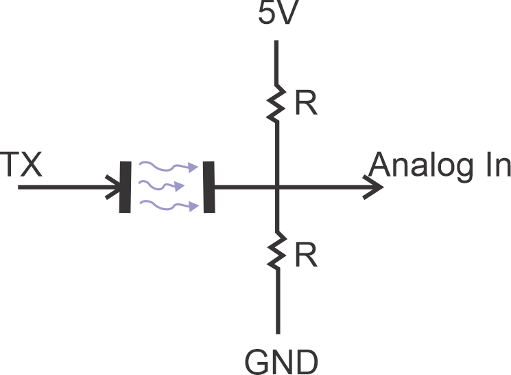
I used the Terrenino board I made in Output Devices Week. I also made a module for the electrodes using KiCAD to design.
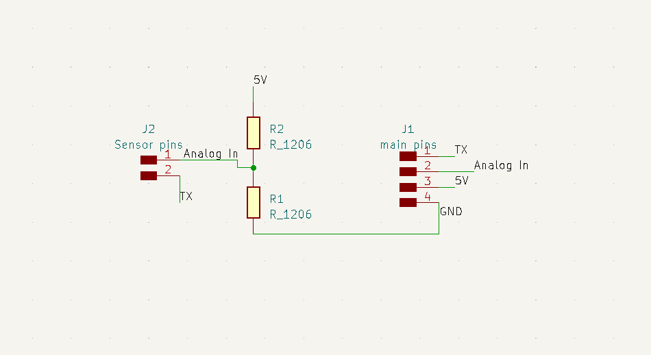
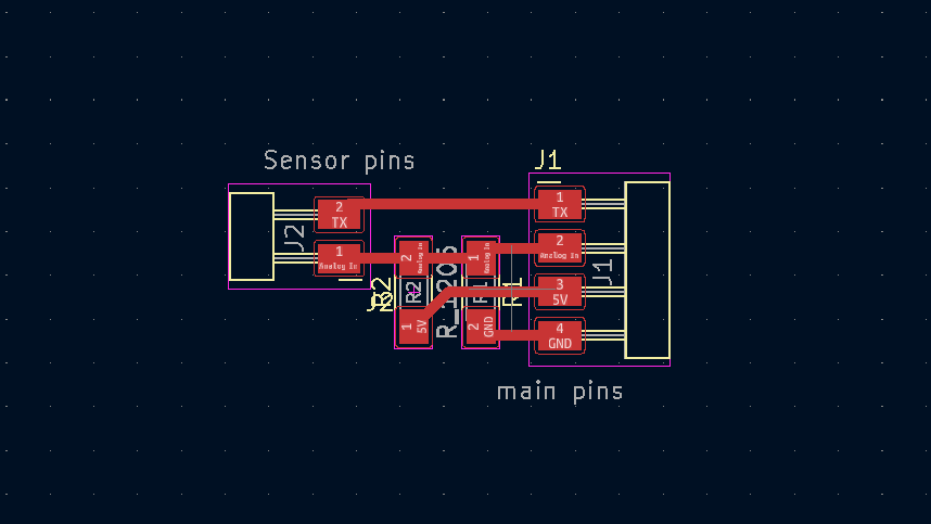

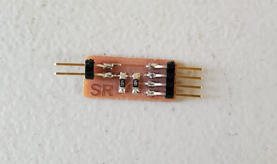
I attached the module to my board, connecting the reciever to PA4 and the transmitter to PA5 and the other two pins to VCC and GND. The electrode pins of the module were each connected to a strip of copper tape which I stuck on the table's surface with a little space between.
I used Pedro Chana's program which tests force.
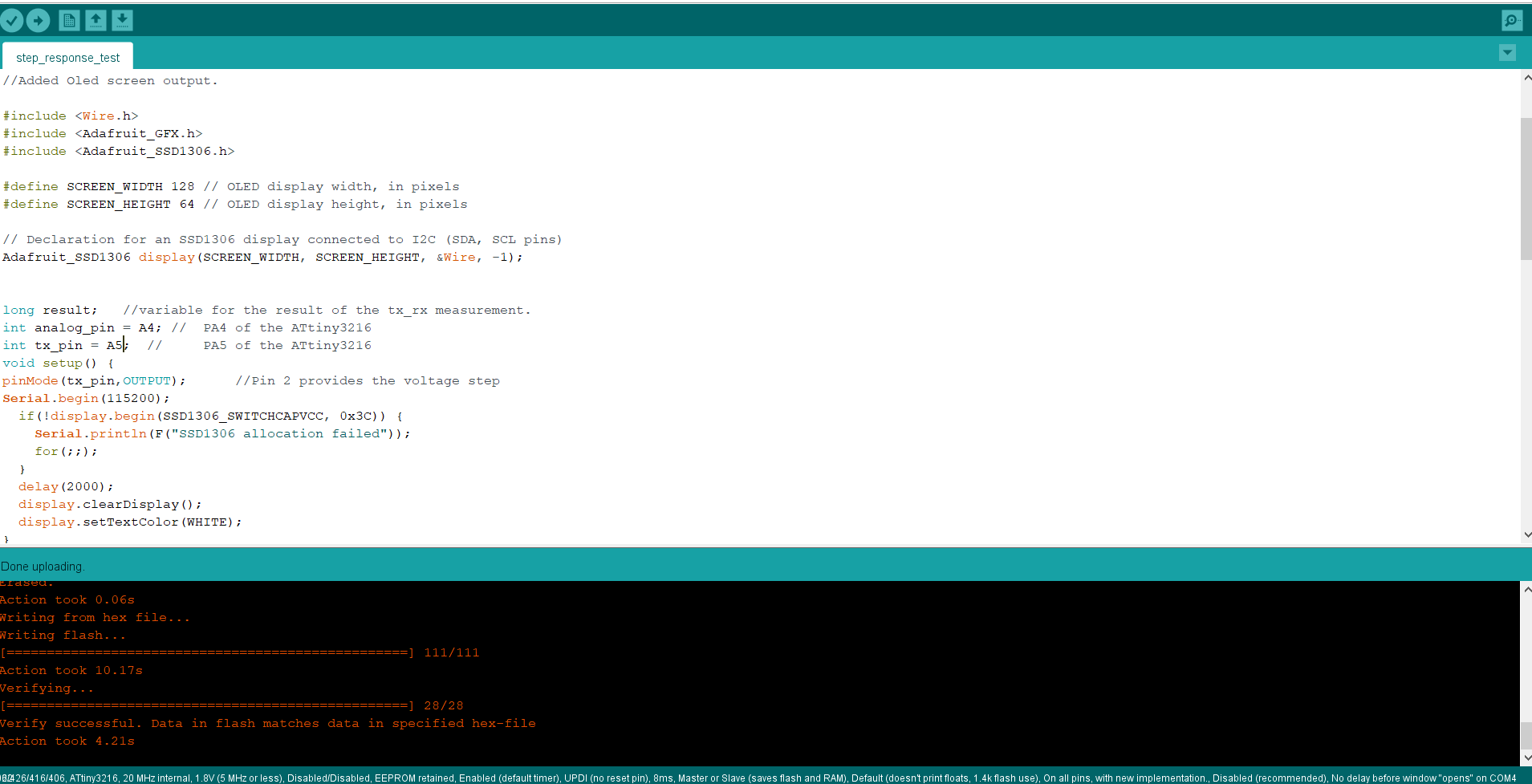
            //tx_rx03  Robert Hart Mar 2019.
//https://roberthart56.github.io/SCFAB/SC_lab/Sensors/tx_rx_sensors/index.html

//Modified from Adrián´s Adrianino´s step response: https://fabacademy.org/2020/labs/leon/students/adrian-torres/adrianino.html#step
//Pin changes.
//Added digitalWriteFast.
//Added Oled screen output.

#include *Wire.h*
#include *Adafruit_GFX.h*
#include *Adafruit_SSD1306.h* // change asterisks to angle brackets

#define SCREEN_WIDTH 128 // OLED display width, in pixels
#define SCREEN_HEIGHT 64 // OLED display height, in pixels

// Declaration for an SSD1306 display connected to I2C (SDA, SCL pins)
Adafruit_SSD1306 display(SCREEN_WIDTH, SCREEN_HEIGHT, &Wire, -1);


long result;   //variable for the result of the tx_rx measurement.
int analog_pin = A2; //  PA2 of the ATtiny1614
int tx_pin = A1;  //     PA1 of the ATtiny1614
void setup() {
pinMode(tx_pin,OUTPUT);      //Pin 2 provides the voltage step
Serial.begin(115200);
  if(!display.begin(SSD1306_SWITCHCAPVCC, 0x3C)) {
    Serial.println(F("SSD1306 allocation failed"));
    for(;;);
  }
  delay(2000);
  display.clearDisplay();
  display.setTextColor(WHITE);
}


long tx_rx(){         //Function to execute rx_tx algorithm and return a value
                      //that depends on coupling of two electrodes.
                      //Value returned is a long integer.
  int read_high;
  int read_low;
  int diff;
  long int sum;
  int N_samples = 100;    //Number of samples to take.  Larger number slows it down, but reduces scatter.

  sum = 0;

  for (int i = 0; i < N_samples; i++){
   digitalWriteFast(tx_pin,HIGH);              //Step the voltage high on conductor 1.
   read_high = analogRead(analog_pin);        //Measure response of conductor 2.
   delayMicroseconds(100);            //Delay to reach steady state.
   digitalWriteFast(tx_pin,LOW);               //Step the voltage to zero on conductor 1.
   read_low = analogRead(analog_pin);         //Measure response of conductor 2.
   diff = read_high - read_low;       //desired answer is the difference between high and low.
 sum += diff;                       //Sums up N_samples of these measurements.
 }
  return sum;
}                         //End of tx_rx function.


void loop() {

result = tx_rx();
result = map(result, 8000, 11000, 0, 1024);  //I recommend mapping the values of the two copper plates, it will depend on their size
Serial.println(result);
delay(100);
delay(100);

   //clear display
  display.clearDisplay();

  // display
  display.setTextSize(1);
  display.setCursor(0,0);
  display.print("Strenght:");
  display.setTextSize(2);
  display.setCursor(0,10);
  display.print(result);
  display.print("");


  display.display();
}
Since my final project requires measuring water level, I decided to try measuring the water in a bottle. I stuck copper tape vertically on the outside of the bottle and connected to my module. I modified Pedro's program where I added four water levels to be read and display on the OLE display. If water is below quarter of the bottle the display will show "Too Low", then 25% + and 75% + and then 100% Full when its filled.
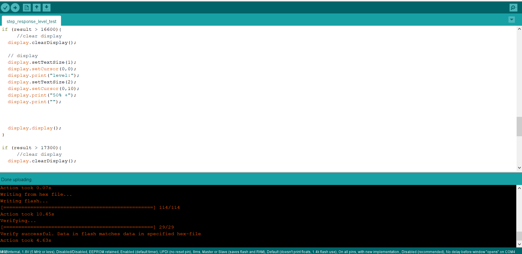
#include
    #include
    #include

    #define SCREEN_WIDTH 128 // OLED display width, in pixels
    #define SCREEN_HEIGHT 64 // OLED display height, in pixels

    // Declaration for an SSD1306 display connected to I2C (SDA, SCL pins)
    Adafruit_SSD1306 display(SCREEN_WIDTH, SCREEN_HEIGHT, &Wire, -1);


    long result;   //variable for the result of the tx_rx measurement.
    int analog_pin = A4; //  PA4 of the ATtiny3216
    int tx_pin = A5;  //     PA5 of the ATtiny3216
    void setup() {
    pinMode(tx_pin,OUTPUT);      //Pin A5 provides the voltage step
    Serial.begin(115200);
      if(!display.begin(SSD1306_SWITCHCAPVCC, 0x3C)) {
        Serial.println(F("SSD1306 allocation failed"));
        for(;;);
      }
      delay(2000);
      display.clearDisplay();
      display.setTextColor(WHITE);
    }


    long tx_rx(){         //Function to execute rx_tx algorithm and return a value
                          //that depends on coupling of two electrodes.
                          //Value returned is a long integer.
      int read_high;
      int read_low;
      int diff;
      long int sum;
      int N_samples = 100;    //Number of samples to take.  Larger number slows it down, but reduces scatter.

      sum = 0;

      for (int i = 0; i < N_samples; i++){
       digitalWriteFast(tx_pin,HIGH);              //Step the voltage high on conductor 1.
       read_high = analogRead(analog_pin);        //Measure response of conductor 2.
       delayMicroseconds(100);            //Delay to reach steady state.
       digitalWriteFast(tx_pin,LOW);               //Step the voltage to zero on conductor 1.
       read_low = analogRead(analog_pin);         //Measure response of conductor 2.
       diff = read_high - read_low;       //desired answer is the difference between high and low.
     sum += diff;                       //Sums up N_samples of these measurements.
     }
      return sum;
    }                         //End of tx_rx function.


    void loop() {

    result = tx_rx();
    result = map(result, 8000, 11000, 0, 1024);  //I recommend mapping the values of the two copper plates, it will depend on their size
    Serial.println(result);
    delay(100);
    delay(100);

    if (result <= 14500){
         //clear display
      display.clearDisplay();

      // display
      display.setTextSize(1);
      display.setCursor(0,0);
      display.print("level:");
      display.setTextSize(2);
      display.setCursor(0,10);
      display.print("Too Low");
      display.print("");


      display.display();
    }

    if (result > 15500){
         //clear display
      display.clearDisplay();

      // display
      display.setTextSize(1);
      display.setCursor(0,0);
      display.print("level:");
      display.setTextSize(2);
      display.setCursor(0,10);
      display.print("25% +");
      display.print("");


      display.display();
    }

    if (result > 16600){
         //clear display
      display.clearDisplay();

      // display
      display.setTextSize(1);
      display.setCursor(0,0);
      display.print("level:");
      display.setTextSize(2);
      display.setCursor(0,10);
      display.print("50% +");
      display.print("");


      display.display();
    }

    if (result > 17300){
         //clear display
      display.clearDisplay();

      // display
      display.setTextSize(1);
      display.setCursor(0,0);
      display.print("level:");
      display.setTextSize(2);
      display.setCursor(0,10);
      display.print("75% +");
      display.print("");


      display.display();
    }

    if (result > 17700){
         //clear display
      display.clearDisplay();

      // display
      display.setTextSize(1);
      display.setCursor(0,0);
      display.print("level:");
      display.setTextSize(2);
      display.setCursor(0,10);
      display.print("Full 100% +");
      display.print("");


      display.display();
    }
    }
The reading varied because my coming too close to the bottle affected the signal.