Measure the power consumption of an output device
Link to Group AssignmentAdd an output device to a microcontroller board you've designed, and program it to do something
Assignment Requirement
Status
Linked to the group assignment page
Completed
Documented how you determined power consumption of an output device with your group.
Completed
Documented what you learned from interfacing output device(s) to microcontroller and controlling the device(s).
Completed
Documented your design and fabrication process or linked to the board you made in a previous assignment.
Completed
Explained the programming process/es you used.
Completed
Explained any problems you encountered and how you fixed them.
Completed
Included original design files and source code.
Completed
Included a ‘hero shot’ of your board.
Completed
An output device with respect to microcontrollers converts the electrical signal into human percievable signal such as sound, light, etc. Attaching an output device to your development board may be simple enough, however, some devices require higher voltage or power than the board can supply. In this case an additional output device can be used to provide or connect the device to an external supply such as a relay or MOSFET.
A single device may consume too much power putting your development board at a strain or preventing other output devices from working properly. The datasheet for the device will give details of its power consumption. Besides the datasheet, the power consumption can be measured or calculated. In the case of the chips used at my lab so far, the output voltage is 5V (it is still good to test with a meter to makes sure). The voltage is known so now I can connect a meter between the power source and the output device in series and measure the current being used. I can now multiply the voltage by the current and I will get the power used since P=VI. In reference to how this was actually done, please see group assignment : Power Consumption.
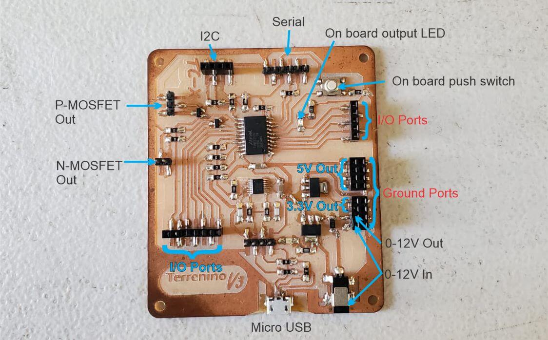
For this assignment I was tasked with attaching an output device to a development board I have designed. I took some inspiration from Adrian Torres's Adrianino and designed my own Terrenino using the ATTiny 3216. I did two previous designs but the one I used is the Terrenino Version 3 with improvements.
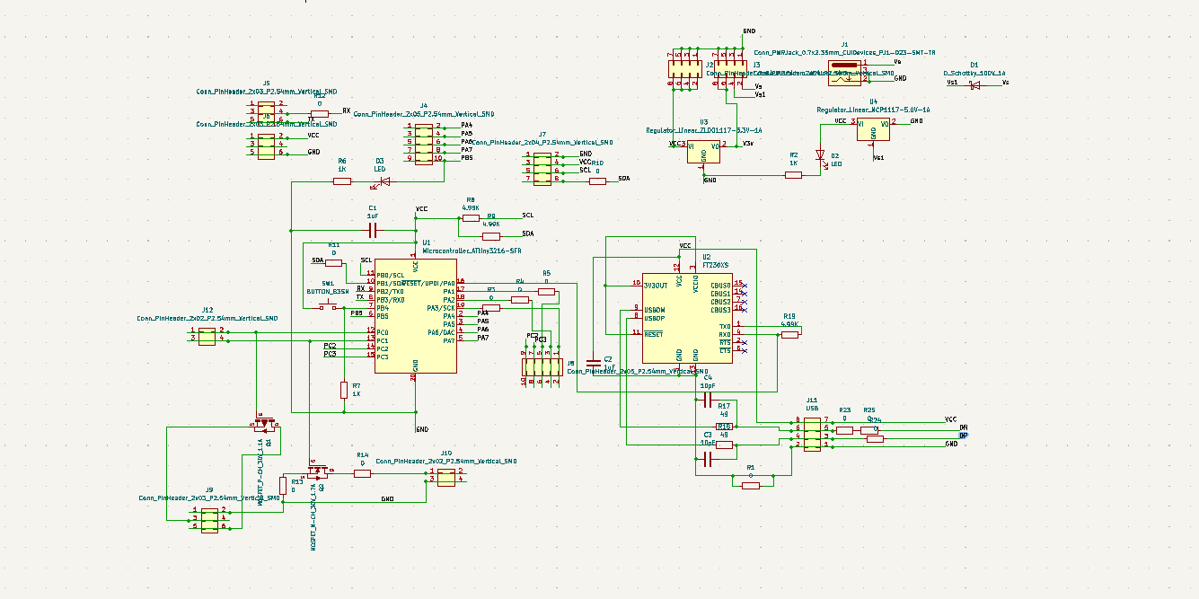
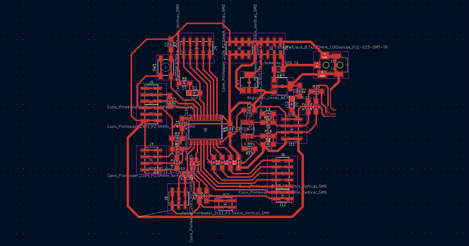
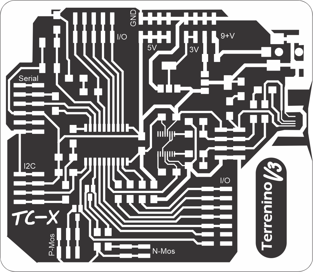
The Terrenino V3 features include:
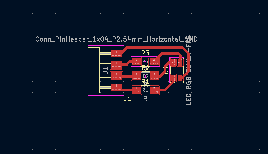
I decided to connect an RGB LED to my development board. An RGB LED is a device that contains three individual LEDs - Red, Green and Blue. The primary colors of physical objects is Red, Yellow and Blue and from this we mix to get all the different colors. However, the primary colors of light is Red, Green and Blue and from this we can achieve any color shade of light.
There are two types of RGB LEDs:
I used a common anode RGB LED for this assignment.
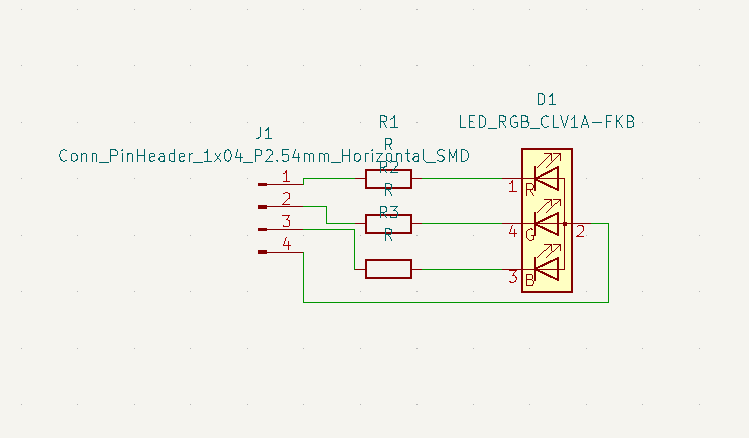

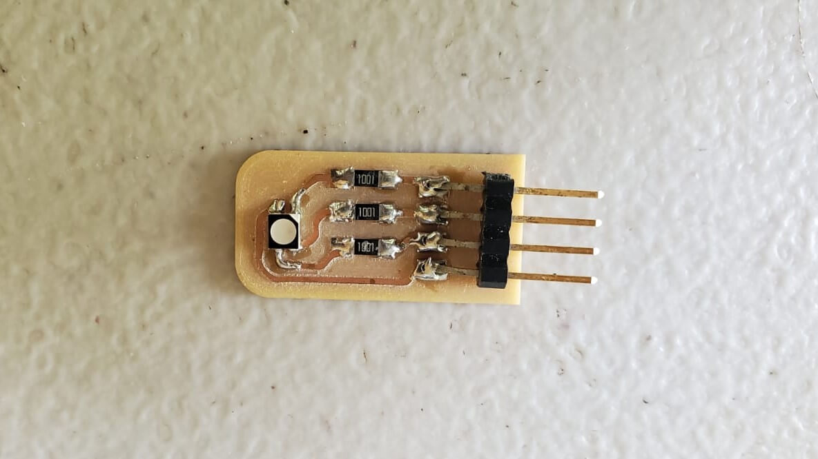
I connected the RGB LED's pins to the Terrenino, PA4 - Red, PA5 - Green, PA6 - Blue (I had actually mistook the red and blue pins in the program at first) and PA7 - Anode (positive). I used "analogWrite" for the cathodes so that if I wanted I could have varied the individual shades from a scale 0 - 255 I used 240 for the max though. Now the PA7 was set "digitalWrite, HIGH" so that a 5V will be supplied to at all times. For this connection I did not use any wires, I just attached the module to the I/O port of the board and thats why I didn't attach the anode to the 5V Out port on the board. I connected my board to the computer and sent the program from the Arduino IDE.
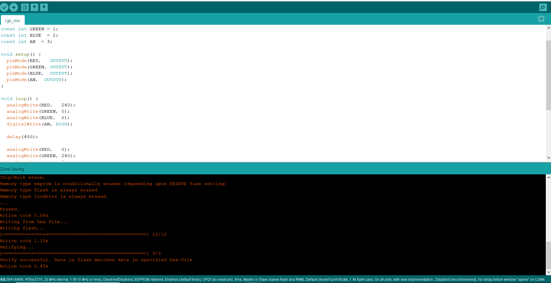
The programming went well and the RGB LED worked, however, it didn't light the way it should have.
I troubleshoot the program and the board and connections. I then realised there were issues with both. First the program, because it was a common anode, the analog scalling 0 - 255 had to be reversed because a HIGH signal was already applied to the anode. Since a HIGH signal was applied to the anode, a LOW signal on the cathode with set the LED at its brightest. The 0would set it at its brightest and the 255 would turn it OFF.
Secondly, since I am using "analogWrite", I need to use analog pins on the board. This is why it is VERY IMPORTANT to read the datasheet. Analog pins are indicated with a sine wave symbol which indicates PWM (Pulse Width Modulation). The output voltage from the I/O ports sends either a HIGH signal (5V) or a LOW signal (0V) nothing in between. PWM is the variation of the wave pulse time. If this time varies, in the case of light, to the human eye it would seem as though the voltage was varying when in fact the voltage is still constant.
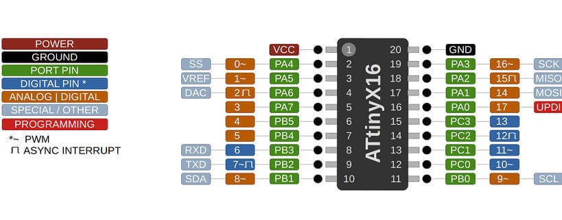
I reconnected my RGB LED using Red - PA3, Green - PA4, Blue - PA5 and Anode - 5V Out. I also made the neccessary changes to the program and finally got it to work as I intended.
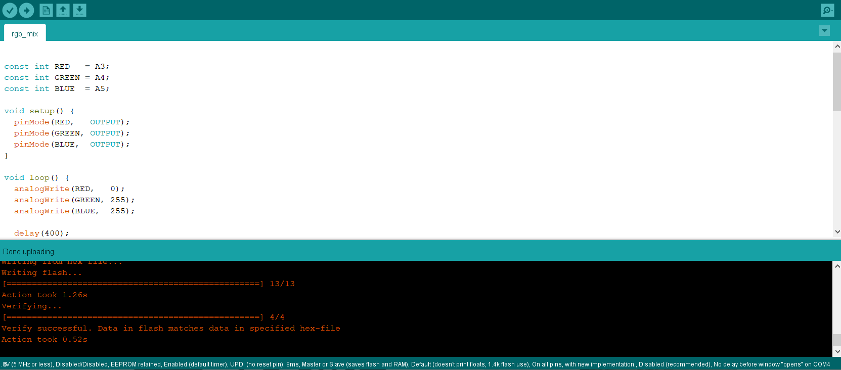
     const int RED   = A3;
     const int GREEN = A4;
     const int BLUE  = A5;

     void setup() {
        pinMode(RED,   OUTPUT);
        pinMode(GREEN, OUTPUT);
       pinMode(BLUE,  OUTPUT);
     }

     void loop() {
       analogWrite(RED,   0);
       analogWrite(GREEN, 255);
       analogWrite(BLUE,  255);

       delay(400);

       analogWrite(RED,   0);
       analogWrite(GREEN, 0);
       analogWrite(BLUE,  255);

       delay(400);

      analogWrite(RED,   255);
      analogWrite(GREEN, 0);
      analogWrite(BLUE,  255);

      delay(400);

      analogWrite(RED,   255);
      analogWrite(GREEN, 0);
      analogWrite(BLUE,  0);

      delay(400);

      analogWrite(RED,   255);
      analogWrite(GREEN, 255);
      analogWrite(BLUE,  0);

      delay(400);

      analogWrite(RED,   0);
      analogWrite(GREEN, 255);
      analogWrite(BLUE,  0);

      delay(400);


     }
Just a note, the wire colors don't match the light in case you're wondering.
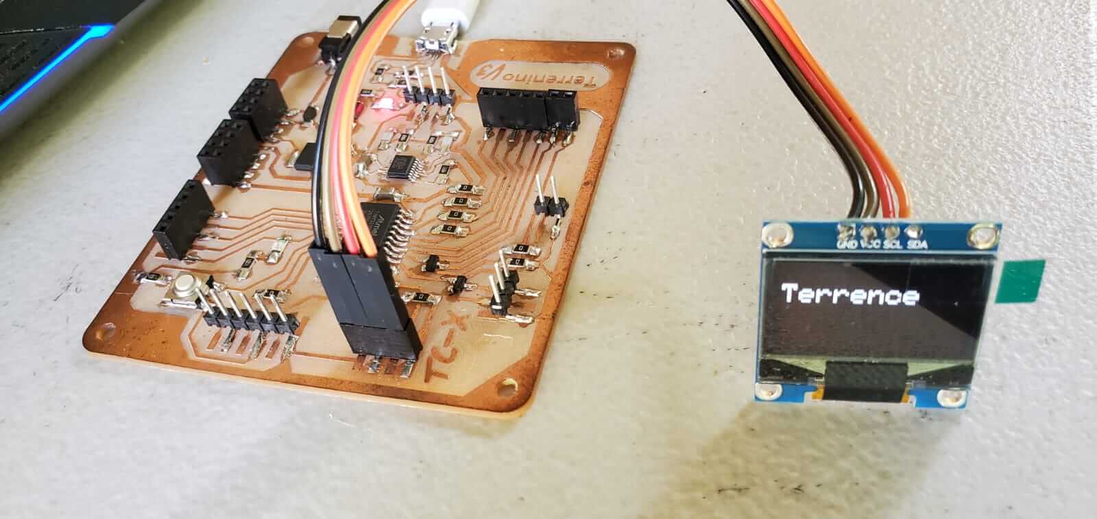
In addition to trying the RGB LED I decided to try display something on an OLED Screen. OLED (Organic Light-Emitting Diode) uses the technology where each individual pixel emits its own light and the screen does not require a backlight. The screen I used requires I2C (Inter-Integrated Circuit) communication from the board. I decided to try this display screen because I will be including it in my Final project.
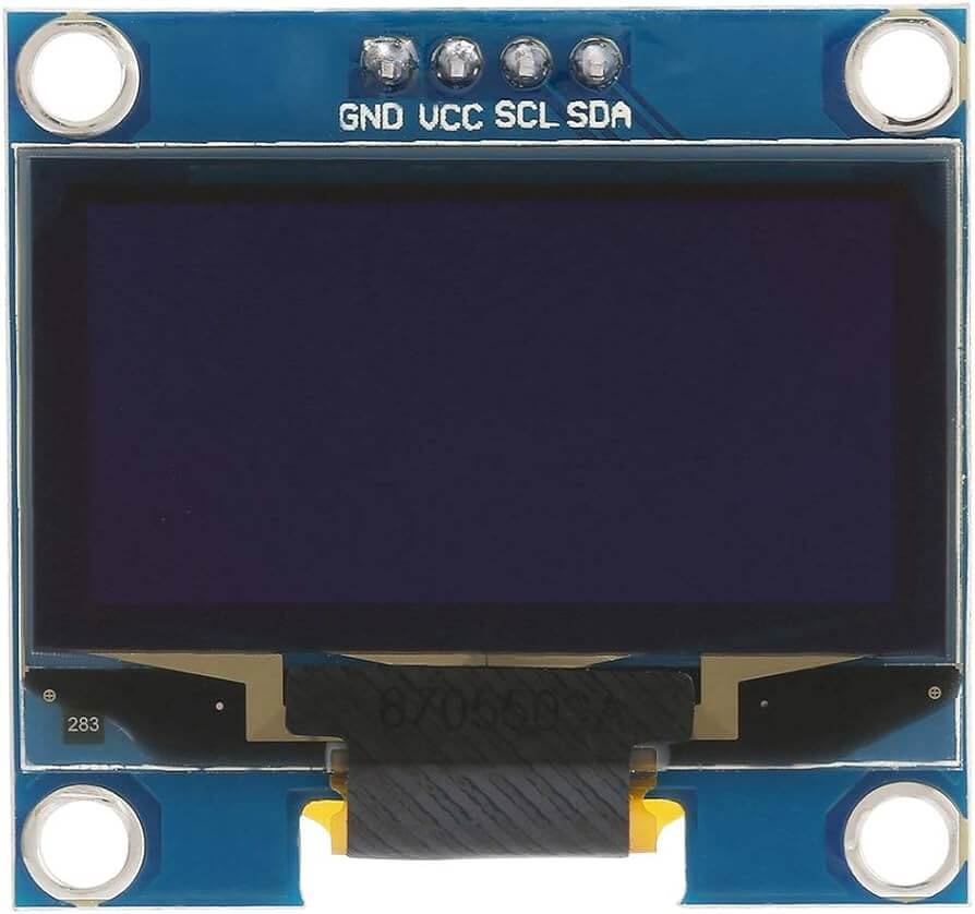
The Terrenino board has an I2C port. For this port I placed two 4.99K ohm pull-up resistors, one for SDA (Serial Data) and SCL (Serial Clock) each to VCC. This is to help stabalise the data signals being transmitted.
I used Pedro Chana's OLED program to test my screen. I just replaced his display information with my name. In order for the Arduino IDE to upload the program to my board, I first had to install Adafruit_SSD1306 library. From the Arduino IDE I selected Sketch from the menu tab at the top, then I selected Include libraries and I open Library Manager and searched and installed the library. For any program to run this display the wire.h, Adafruit_GFX.h, Adafruit_SSD1306.h and splash.h libraries must be included.
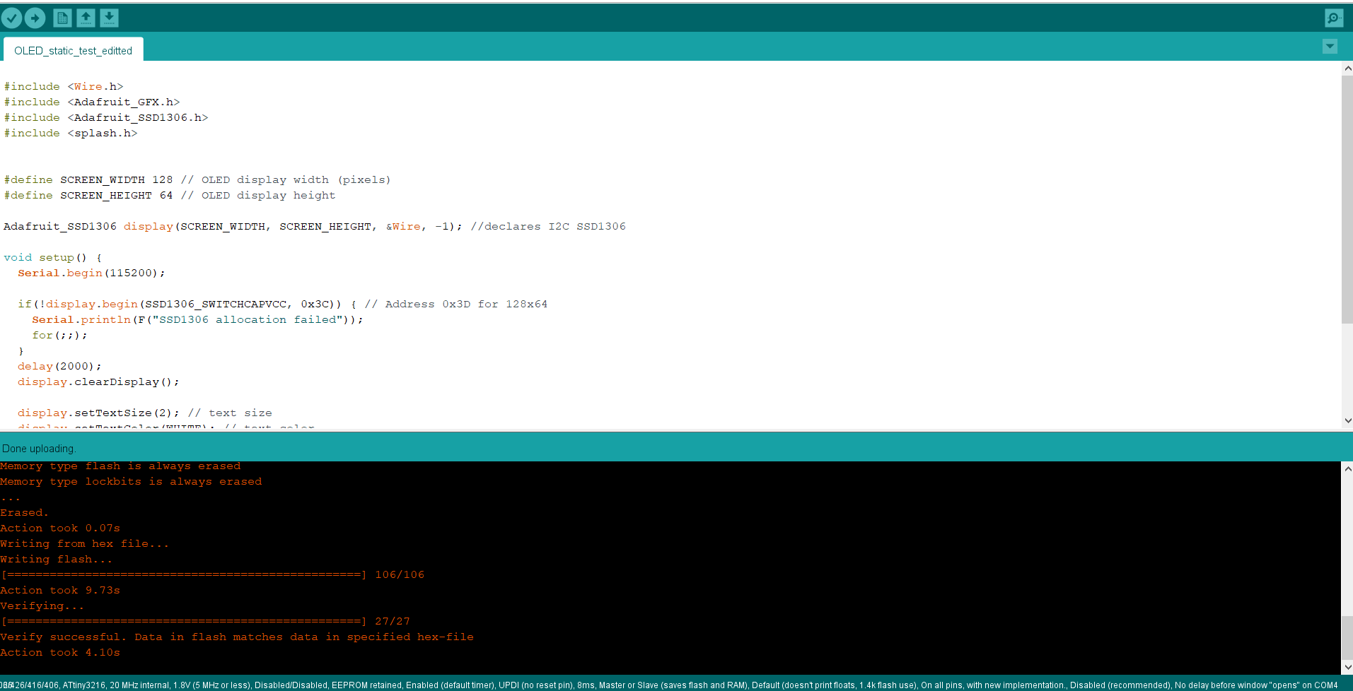
    #include *Wire.h*
    #include *Adafruit_GFX.h*
    #include *Adafruit_SSD1306.h*
    #include *splash.h*          //replace asterisks with angle brackets


    #define SCREEN_WIDTH 128 // OLED display width (pixels)
    #define SCREEN_HEIGHT 64 // OLED display height

    Adafruit_SSD1306 display(SCREEN_WIDTH, SCREEN_HEIGHT, &Wire, -1); //declares I2C SSD1306

    void setup() {
      Serial.begin(115200);

      if(!display.begin(SSD1306_SWITCHCAPVCC, 0x3C)) { // Address 0x3D for 128x64
        Serial.println(F("SSD1306 allocation failed"));
        for(;;);
      }
      delay(2000);
      display.clearDisplay(); // clear all display

      display.setTextSize(2); // text size
      display.setTextColor(WHITE); // text color
      display.setCursor(0, 10); // text position on display
      display.println("Terrence"); // text displayed
      display.display();
    }

    void loop() {

    }