Hydroponics/Aeroponics systems have brought somewhat of an ease to all the hard work that comes with agriculture yet depending on the expanse of a system or farm it still demands some time and effort. These systems require water testing and monitoring, fertilizer measuring and testing, etc. From my own experience, an issue I encountered was if there is a leak in the reservoir, the water can be drained leaving the plants all dried up if unnoticed over a period of time. My initial idea for the system was to switch to an alternate water source should the main reservoir run too low. I came up with a solution to this by using a media (cocpeat and vermiculite) in my plant holders. This was a partial solution since some of my plants I placed in nft runs which I didnt use a media. So I still needed to include a system that can monitor or respond to water levels.
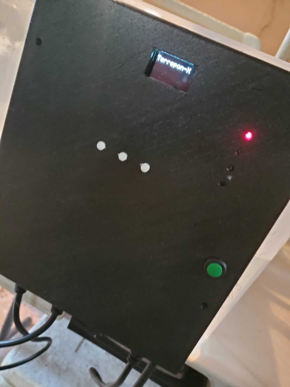
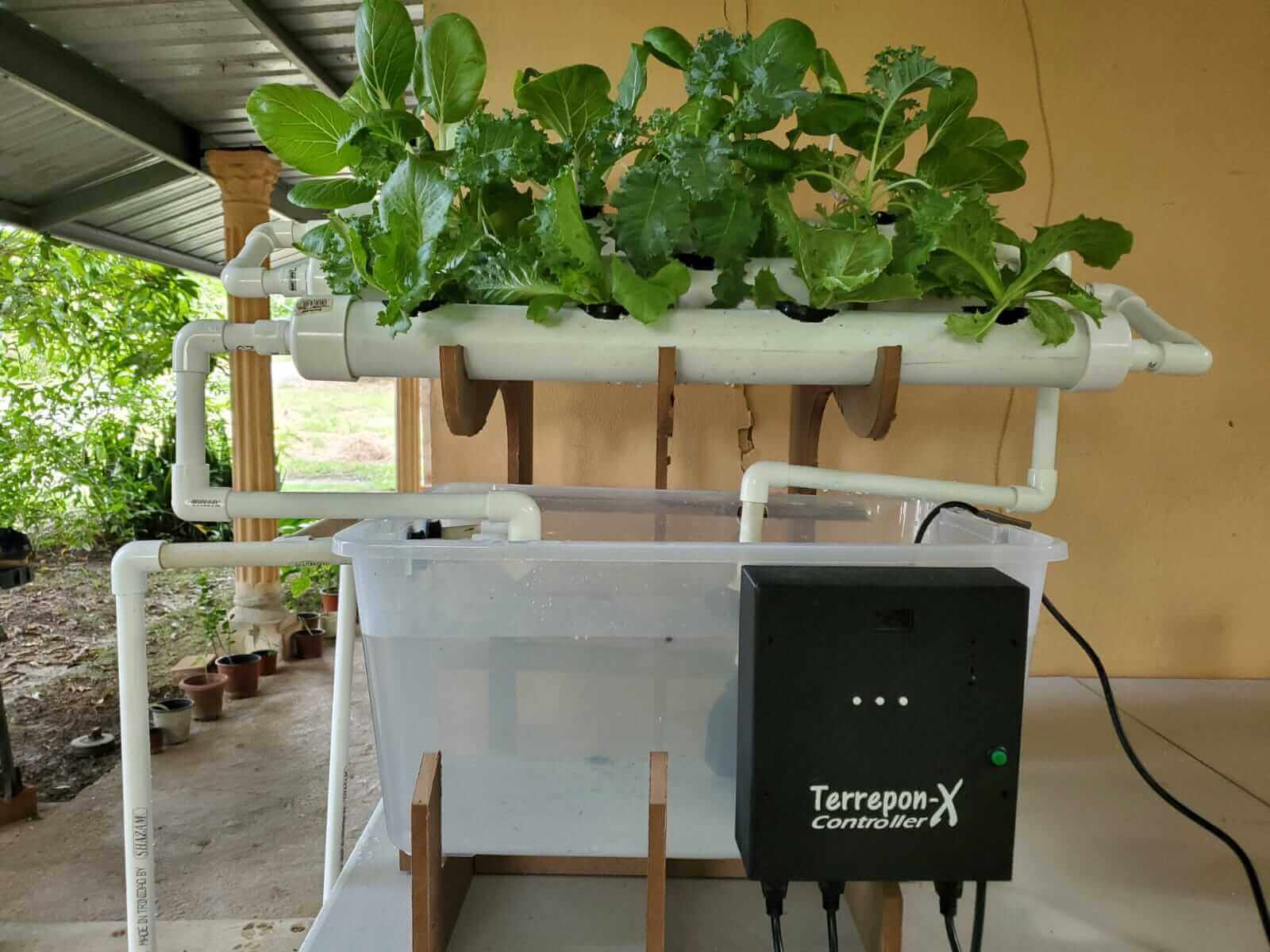
The Terrepon-X controller will be able to detect when the water level runs low and can be viewed on an OLED display. It will also add fertilizer solution to the reservoir. If the water runs below a certain level, the reservoir will be refilled by an external water source and fertilizer will be added. The water will be able to flow to the plants when the reservoir is filled.
I came up with the idea for this project based on experience with my own Hydroponic system. I have done some research trying to find someone who did similiar projects but I didn't find anyone in the Fab Academy with a system that adds fertilizer. I did however found a farmer on youtube known as the "Mad Scientist" with a more advanced system to my idea. This system I found gave me the push to realise it can be done.
I will design the entire control unit which includes the microcontroller board, the housing case and the sensor probe. I will also design the frame structure that will support the reservoir and plants as well as the nft run for the plants as well as the reservoir intake system.
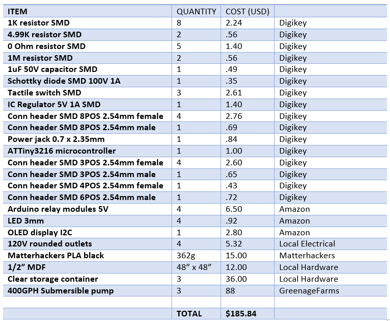
The plumbing materials, submersible pumps and storage container will be purchased at a local hardware. The remaining materials and components will be purchased online from Amazon and Digikey.
I intend to make all the parts of this project except for the reservoir.
No major questions at this point.
The system will be evaluated based on three spirals:
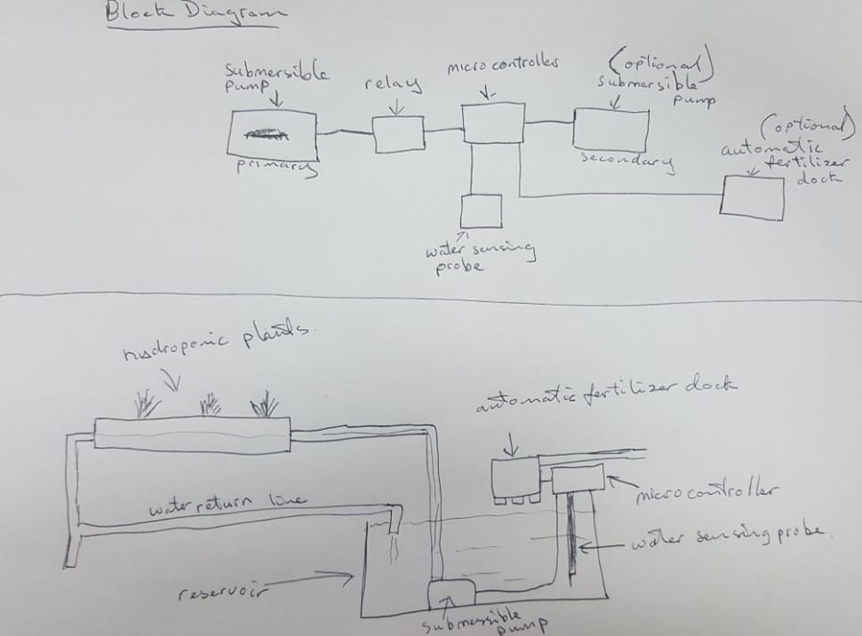
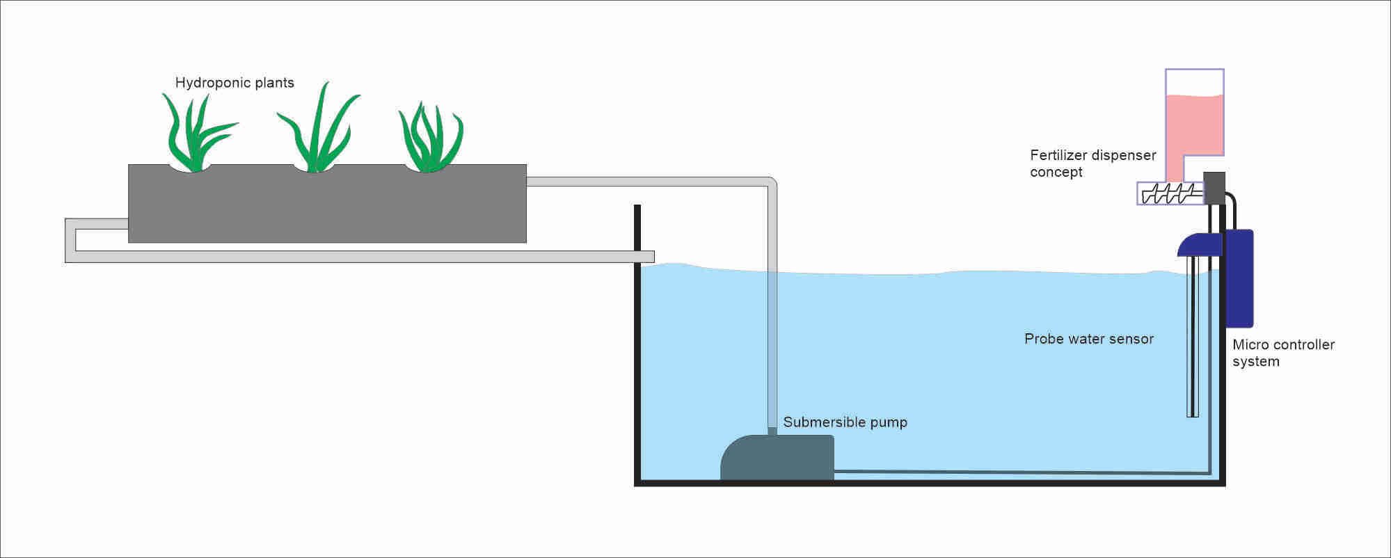
The following image is the sketch for the initial idea of my final project.
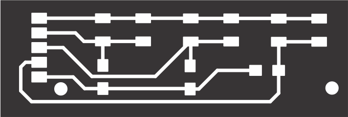
The microcontroller main board was the first part to be designed. As my previous assignments, this board was designed using KiCAD EDA. The board included:
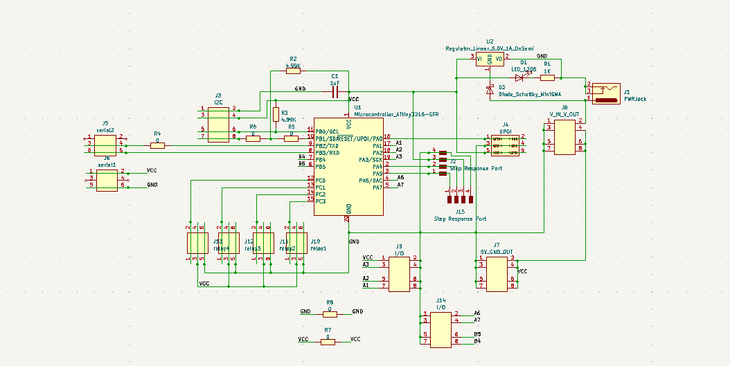
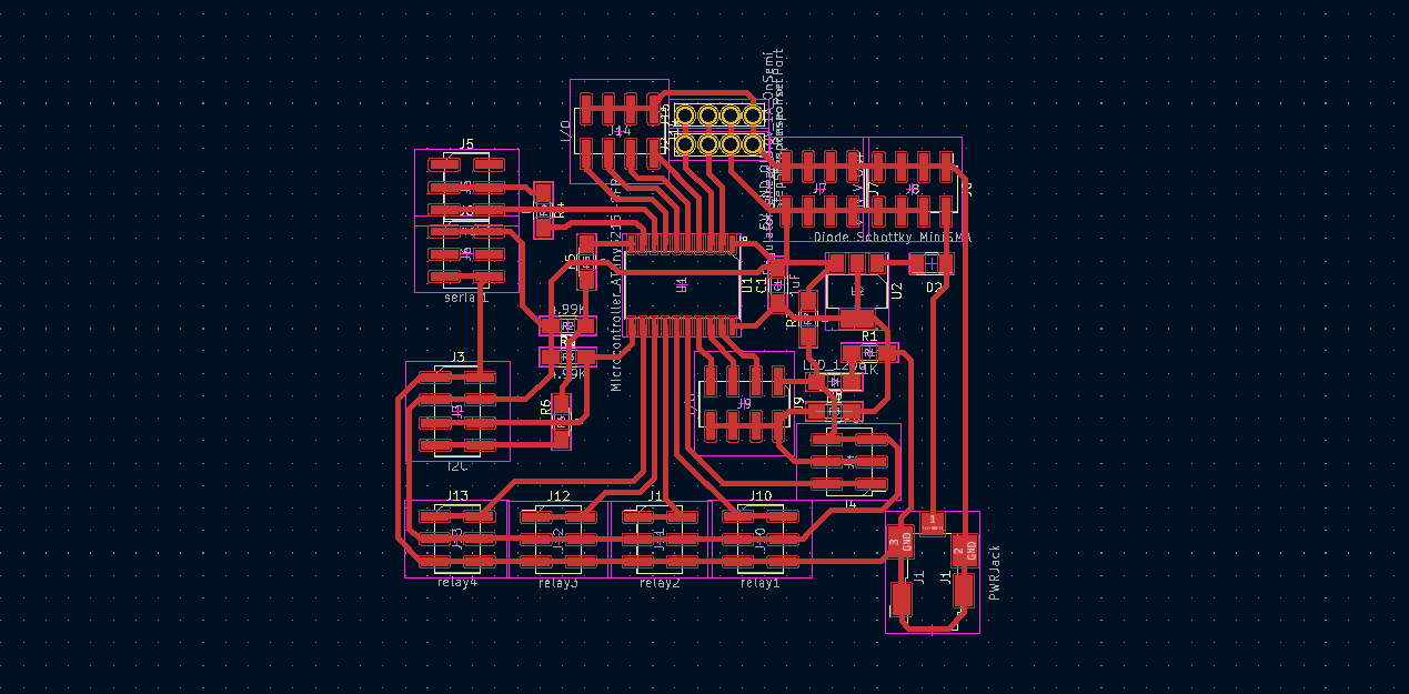
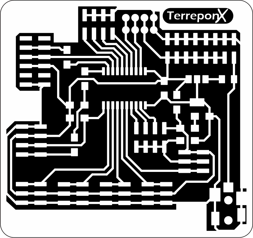
The PCB was milled using the Nomad3 Carbide desktop milling machine as before.
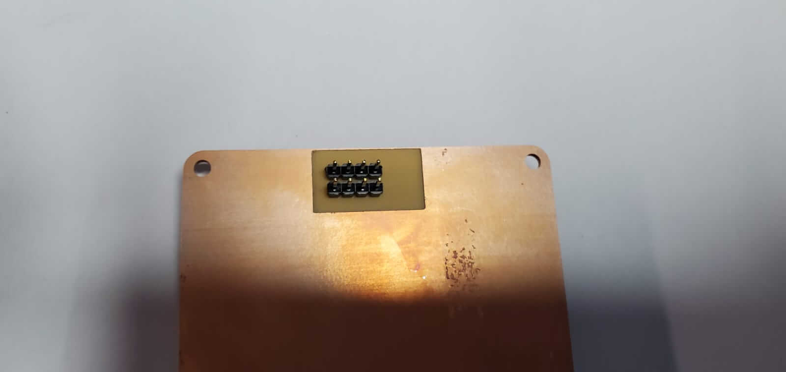
The completed soldered Terrepon-X main board.
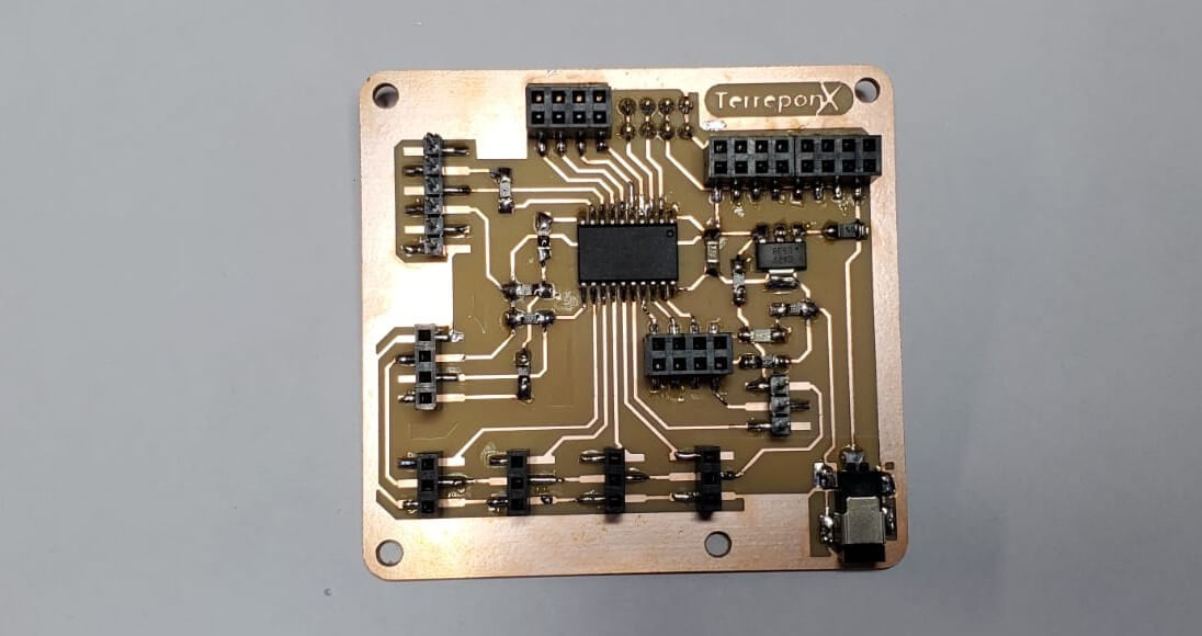
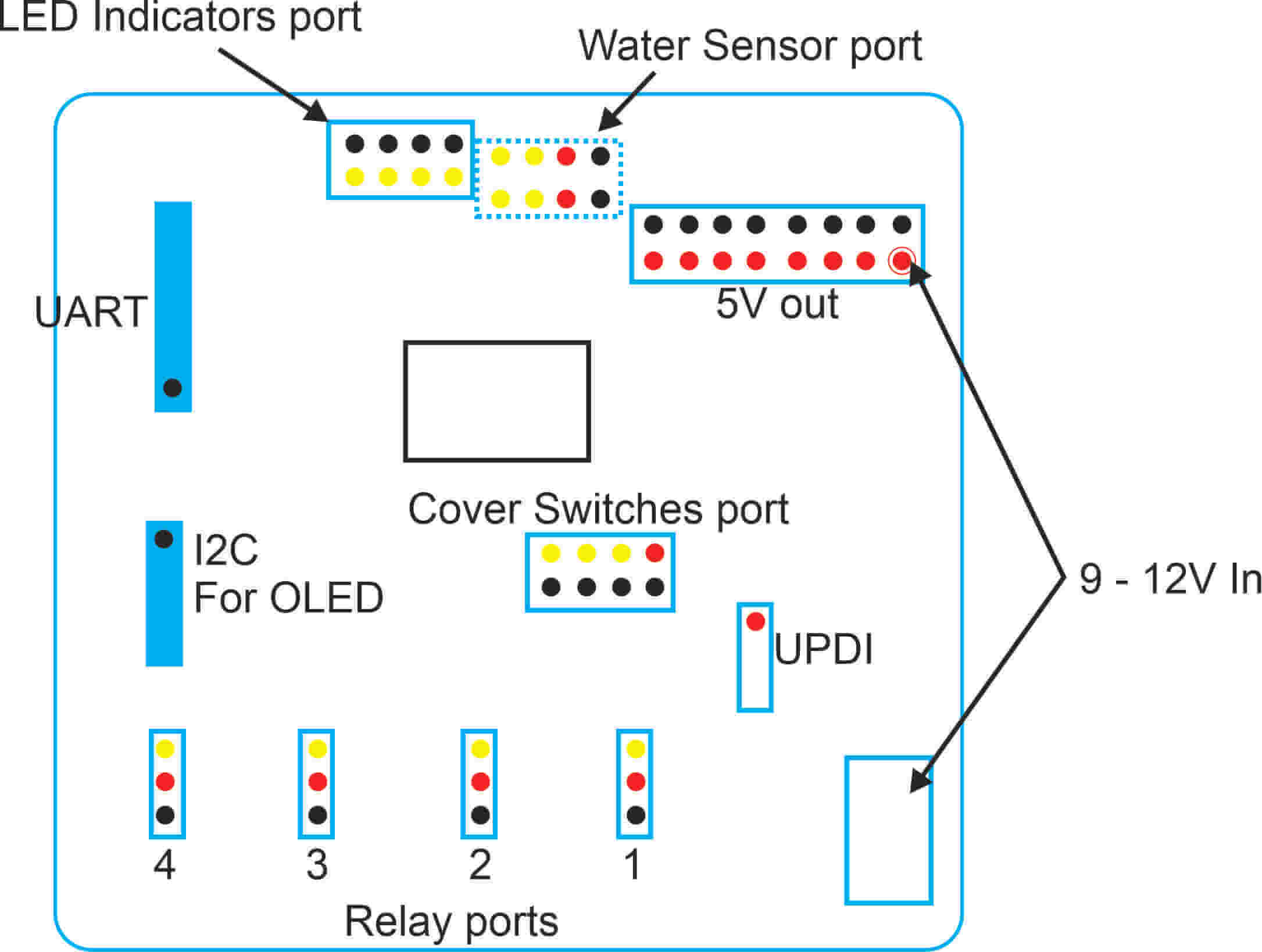
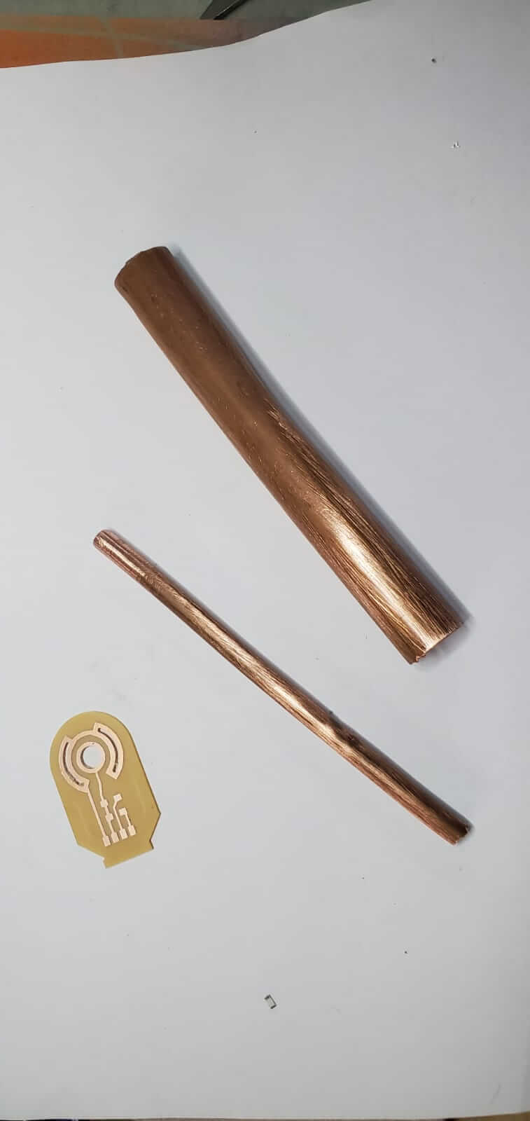
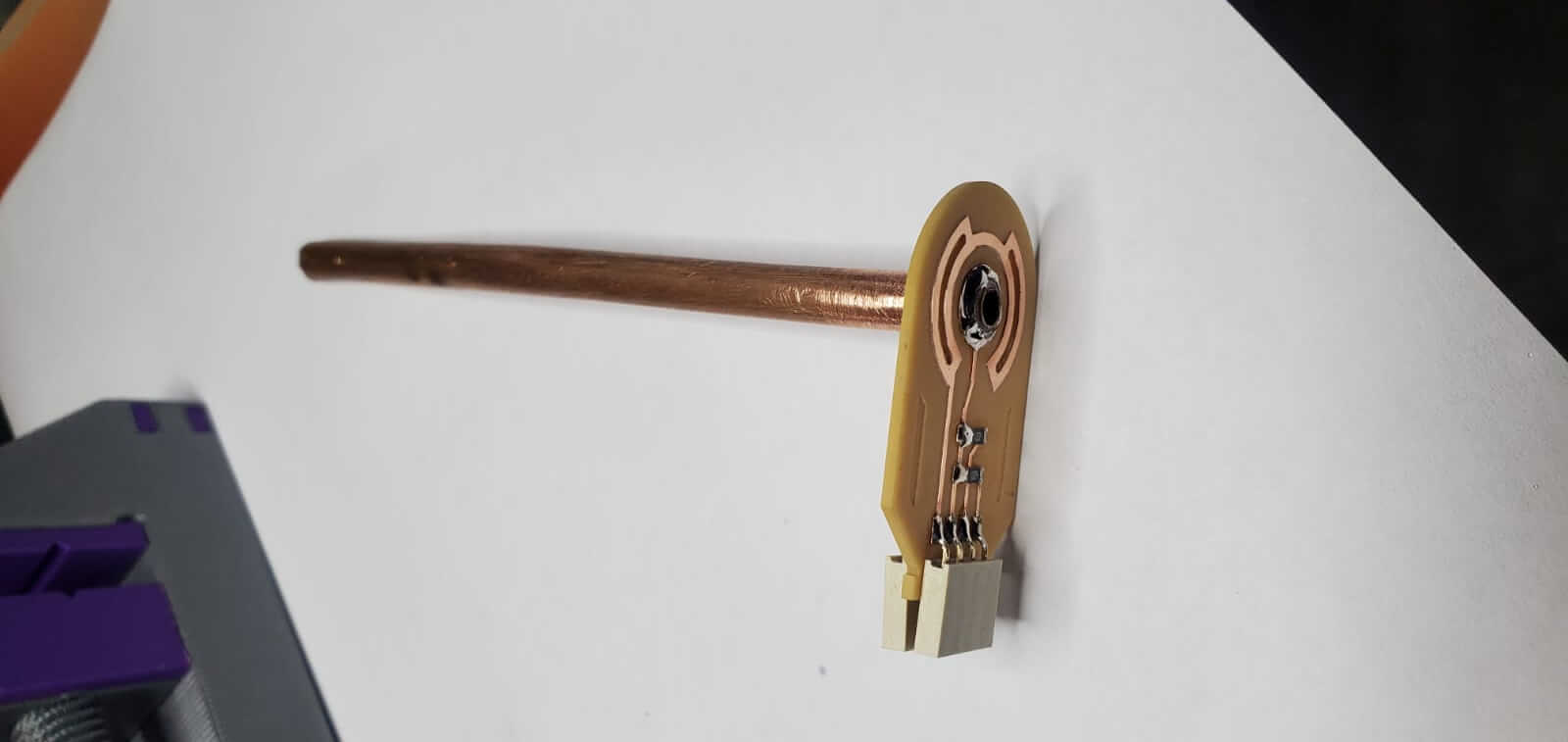
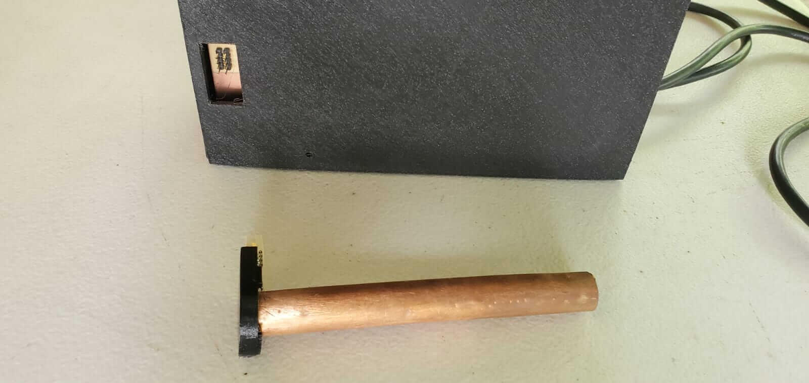
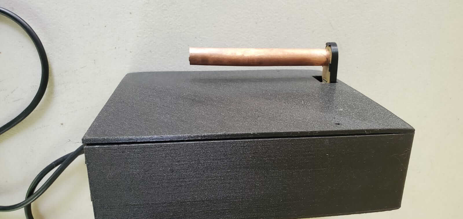
A 2 x 4 male header was soldered to the circuit from the opposite side of the board to connect the water sensor. The water sensor was designed to include 2 1M Ohm resitors forming a step response circuit similar to what was made in week 11. I used 2 pieces of copper tube, a 1/4" for the analog reciever and 5/8" for the transmitter which was placed around the analog reciever. This process was recommended by Neil Gershenfeld.

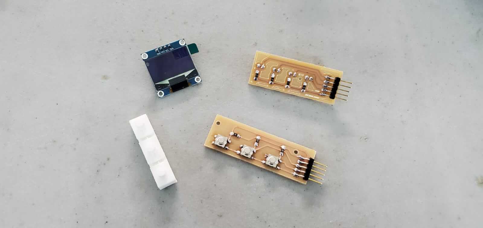
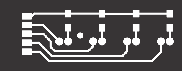
In addition I also made a switch circuit which has 3 tactile push buttons. I also made an LED indicator board with 4 LEDs attached.
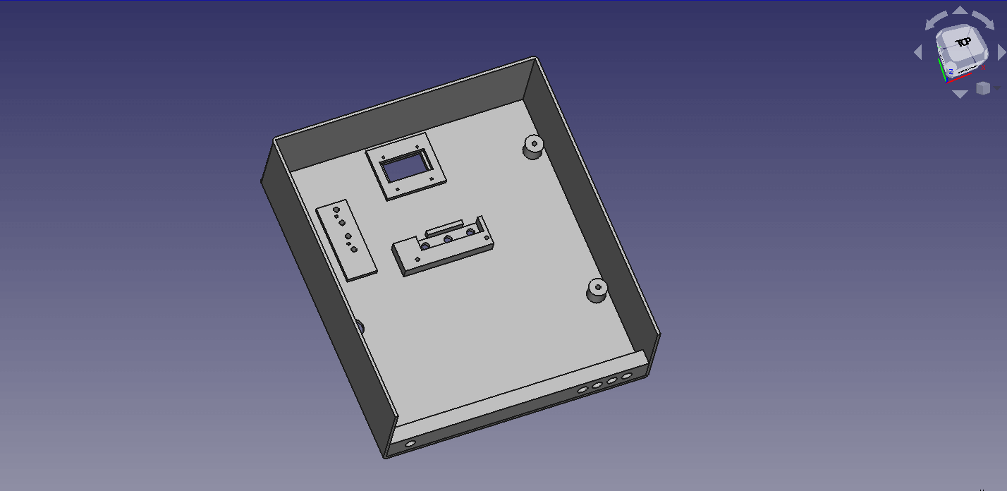
The housing containment for the device was designed using FreeCAD.
The housing incorporated a base and a cover.
The base accomodated:
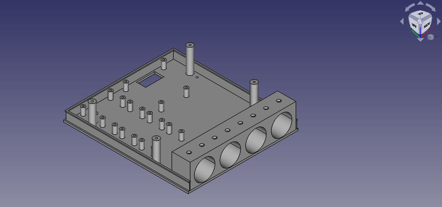
The cover accommodated:
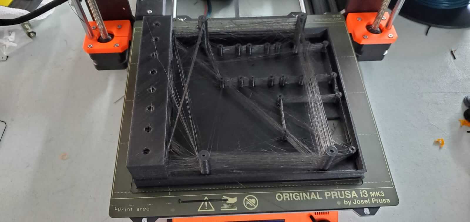
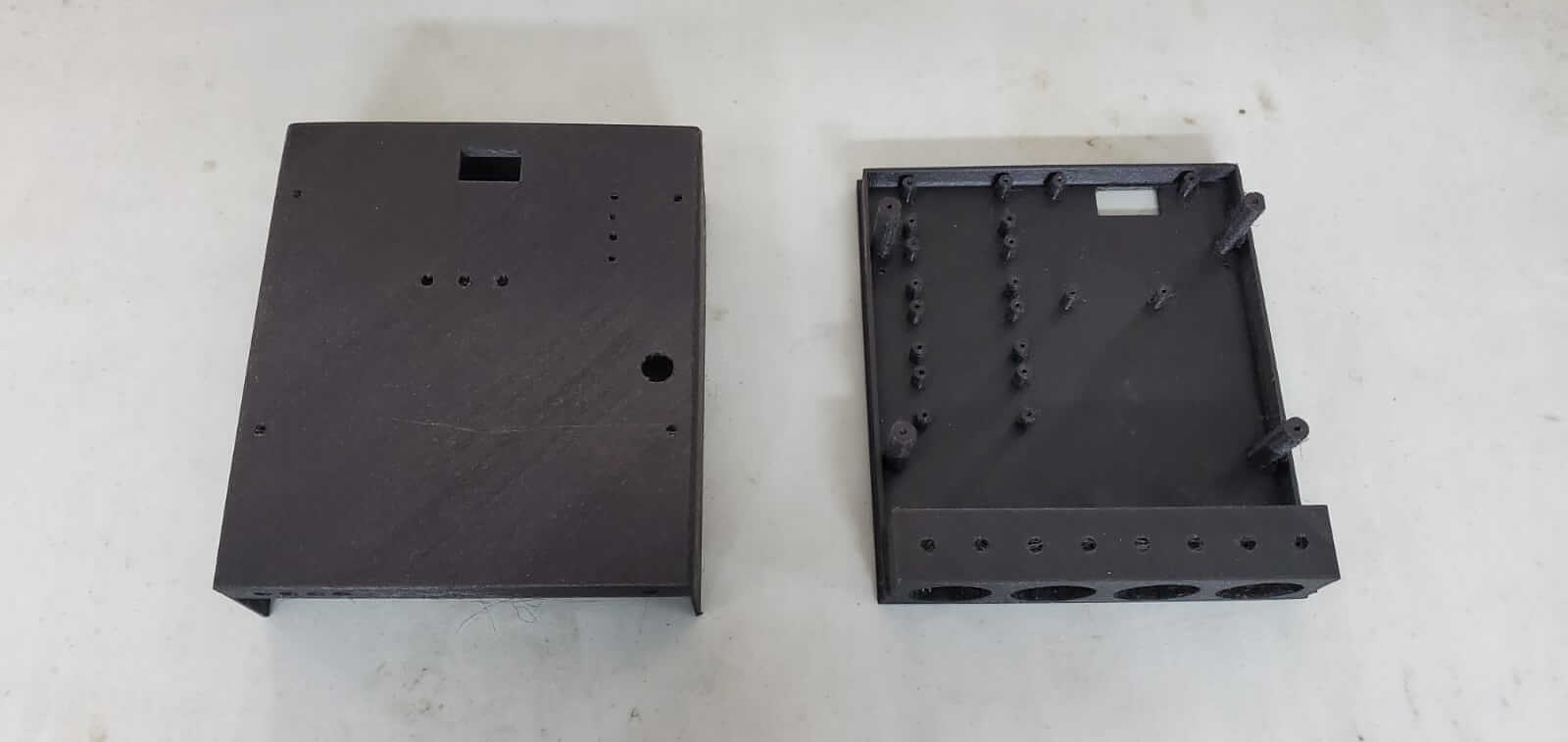
The housing was then 3D printed using the Prusa MK3 3D printer.
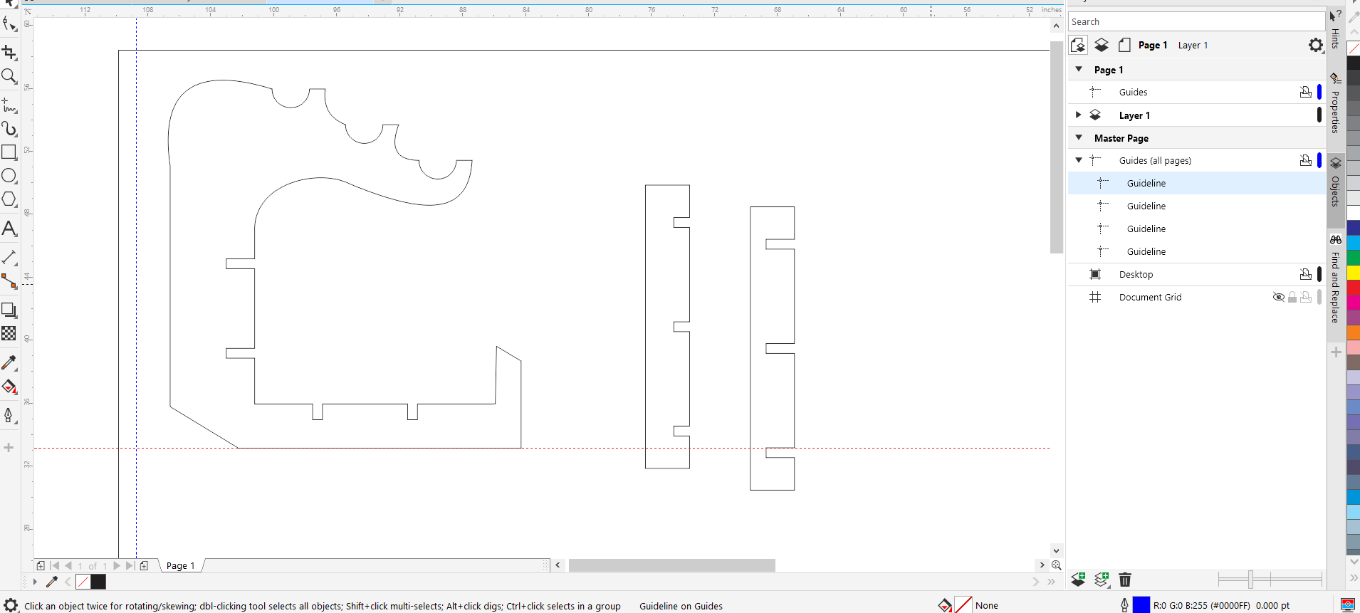
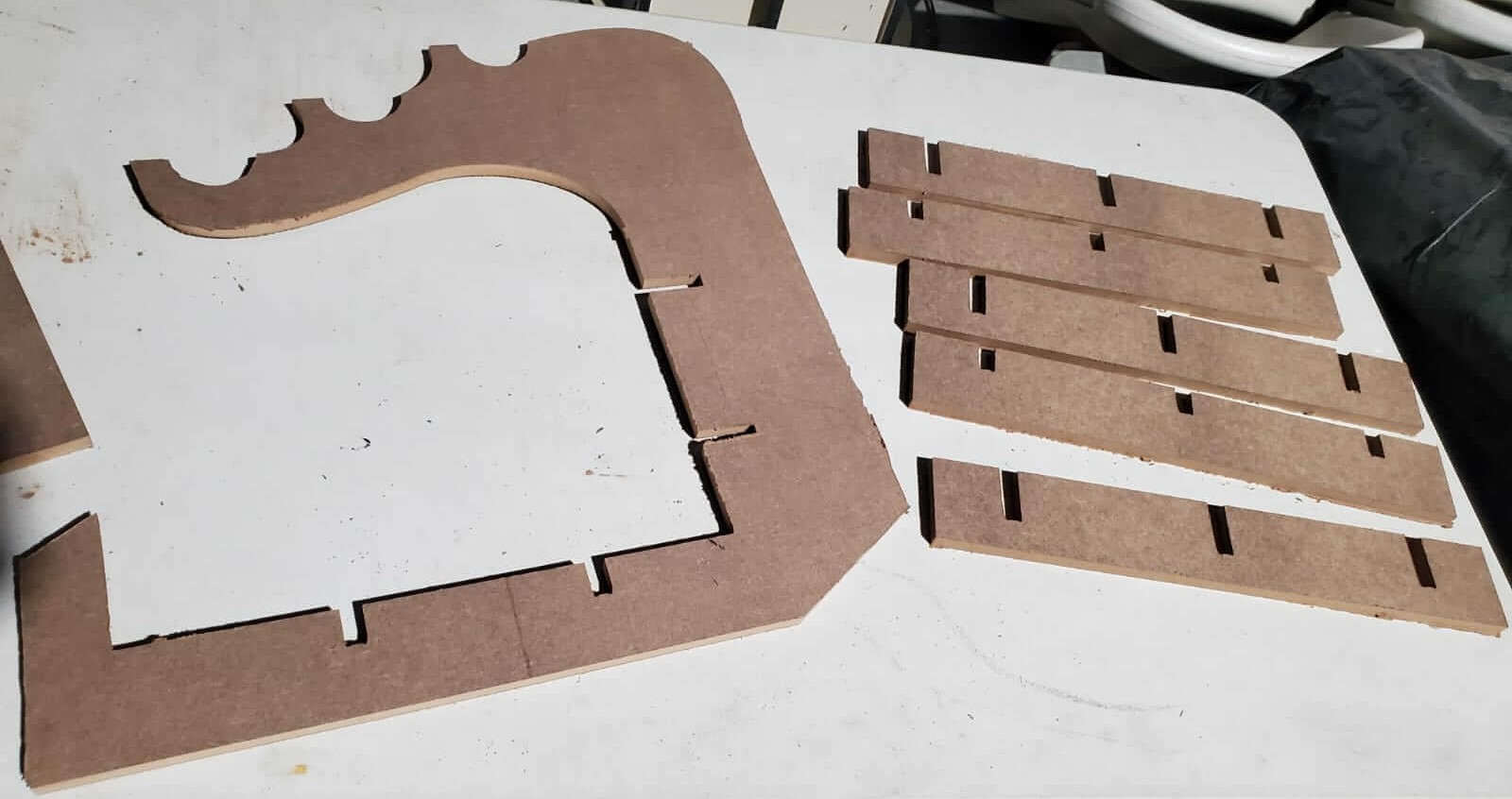
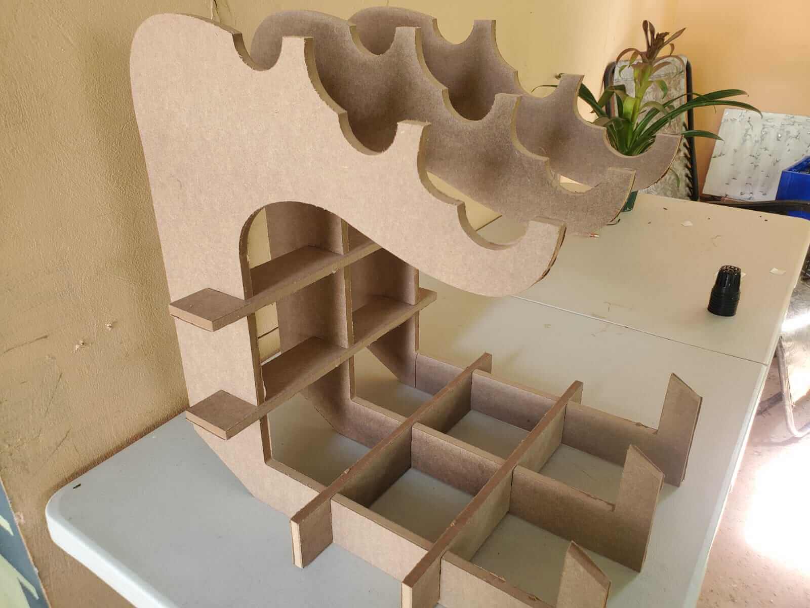
The reservoir support was made to hold three 2" x 2' PVC plant NFT (Nutrient Film Technique) runners. It was designed using CorelDraw and cut using the X-Carve CNC Router.
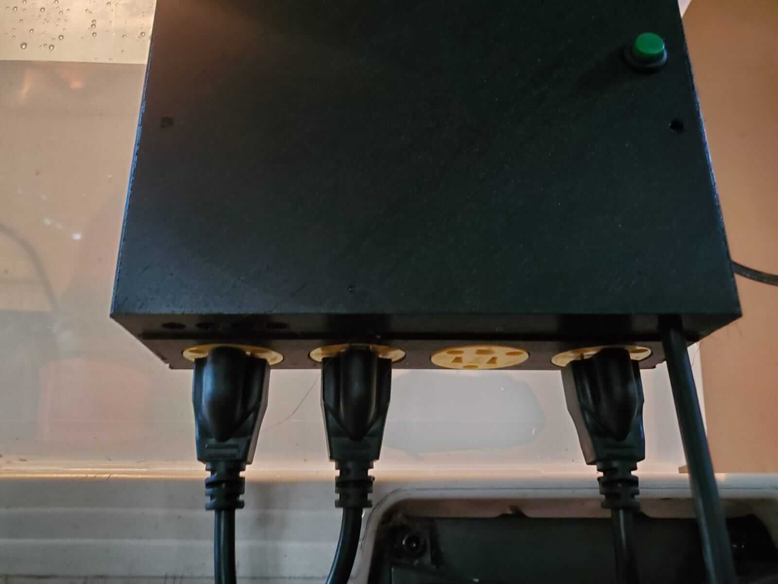
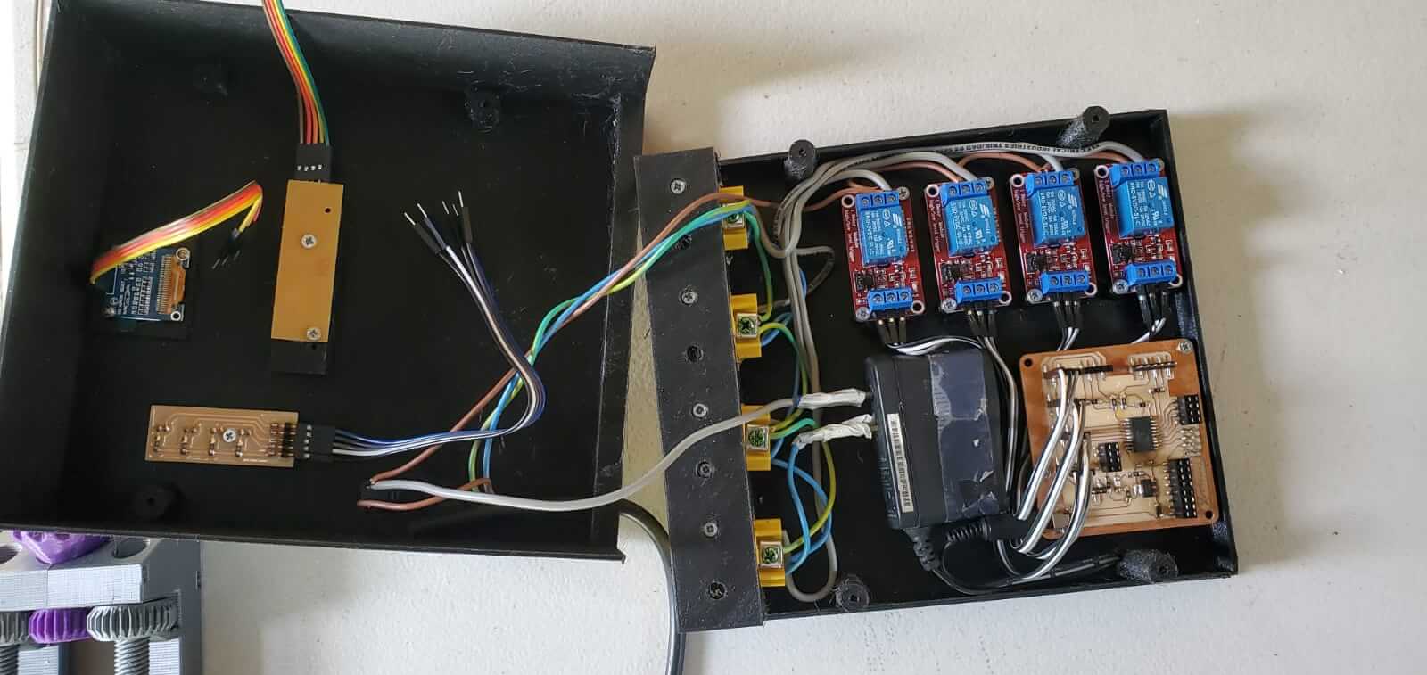
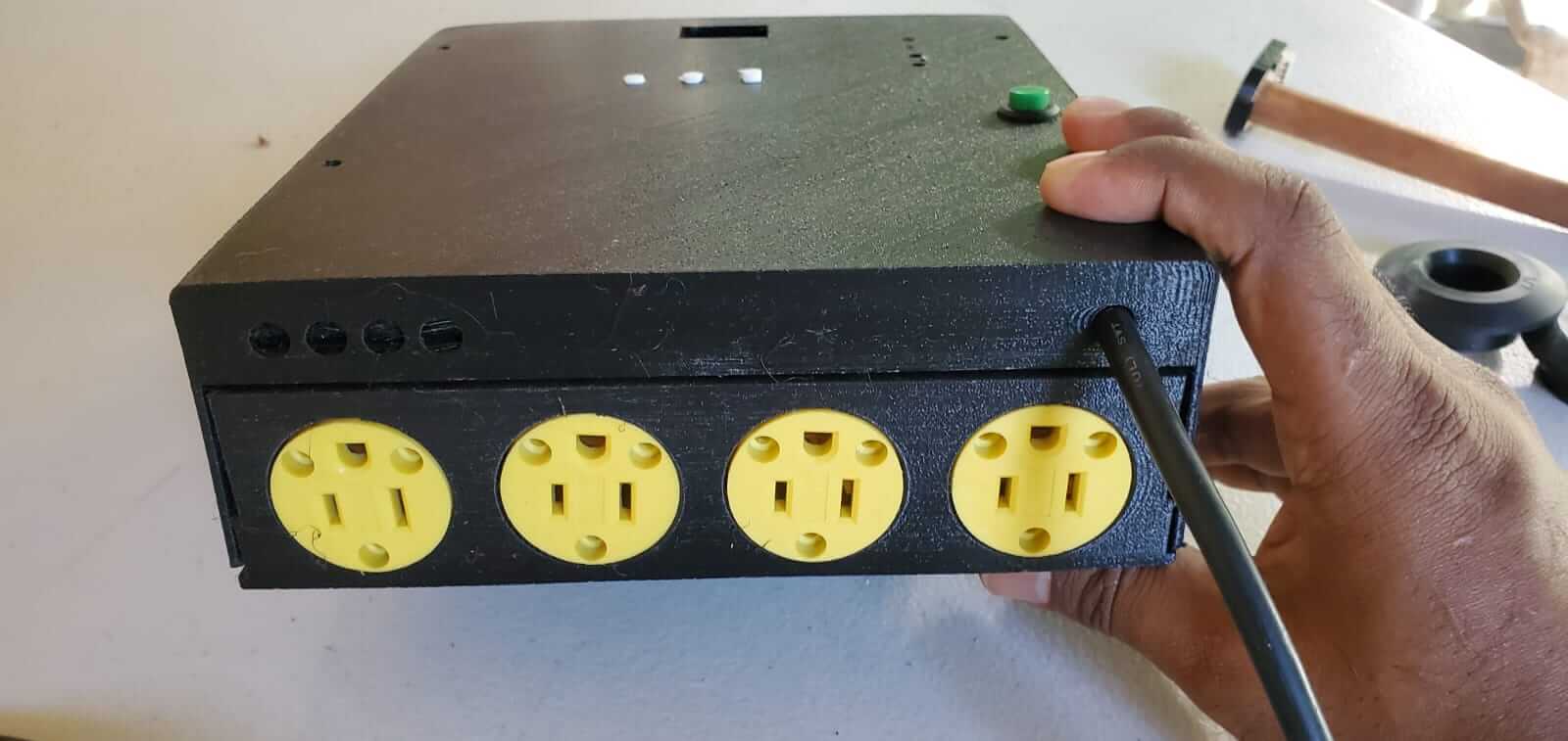
The relays and the plug outlets were assembled first because they required the most wiring and also because of the outlets position on the base.
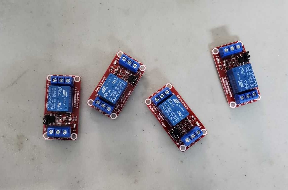
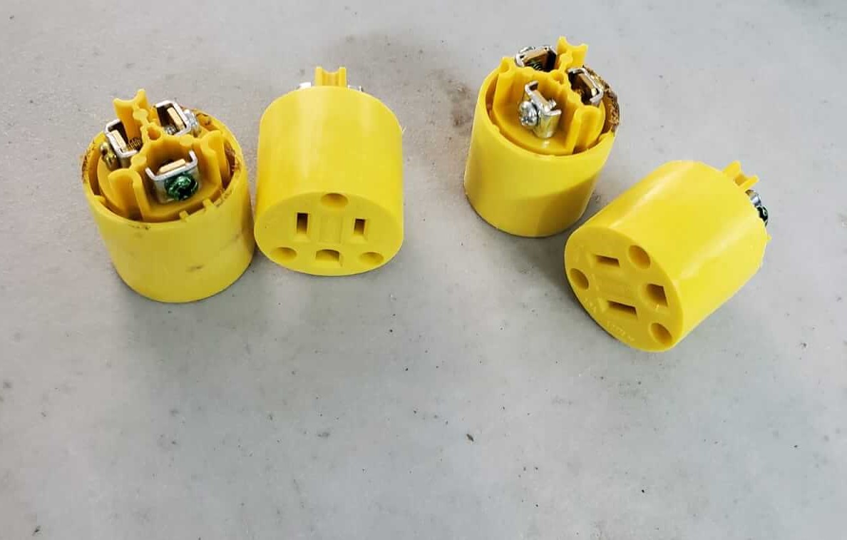
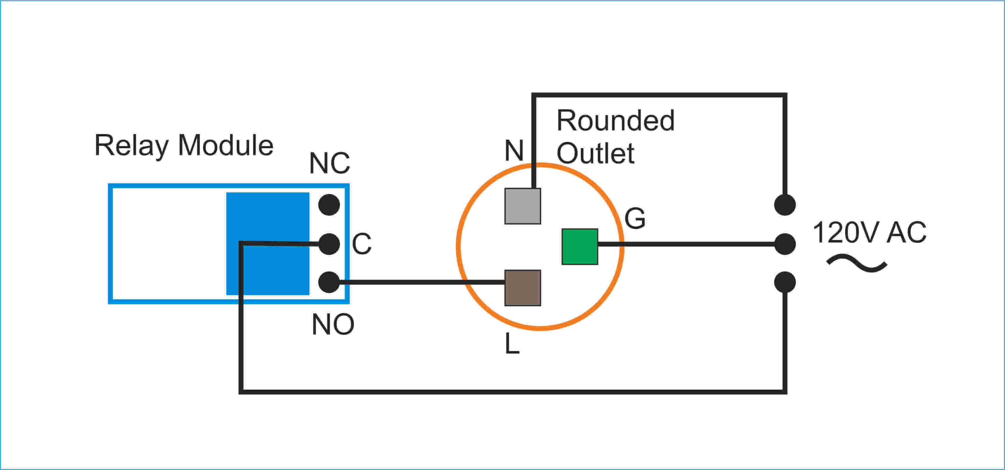
The image below shows how the connection is made between relay and back of the plug outlet.
The circuit boards and remaining components were then attached.
A simple program was sent to the main board with a flashing LED just to ensure that the device is powering with no problems.
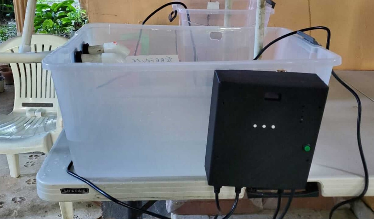
It was time to connect my controller to a test system. I first wrote my program but included the same settings I had in my Input Devices week and sent it to the controller main board. I attached the sensor and powered the controller and I placed the sensor to measure the water level in a cup. I didnt get any changes in the readings. I then realised that beacause of the design of my sensor and the material used I had to play round experimenting with the mapping. It took me a long while but I got through. I made my changes to the program and then attached the controller to a reservoir I made using a clear storage container. I powered the unit and i didnt get any readings yet again. Now I had to experiment againg with the mapping and also the sensor's position until I finally got it reading.
Another thing I realised is that because the analog electrode is so close to the transmitter electrode and also enclosed by it, the readings spontaneously jumps to a much higher value when the water reaches the sensor. It wasn't a big issue, I just had to alter my mapping and set the conditions to accomodate.
//tx_rx03 Robert Hart Mar 2019.
//https://roberthart56.github.io/SCFAB/SC_lab/Sensors/tx_rx_sensors/index.html
//Modified from Adrián´s Adrianino´s step response: https://fabacademy.org/2020/labs/leon/students/adrian-torres/adrianino.html#step
//By: Pedro Chana :https://fabacademy.org/2022/labs/uemadrid/students/pedro-chana/assignment12.html
//Pin changes.
//Added digitalWriteFast.
//Added Oled screen output.
//Modified by Terrence Carew:http://fabacademy.org/2021/labs/vancouver/students/terrence-carew/assignments/final_project.html
//Added level variable.
//Added New Mapping.
//Added Intro display
//Added "millis()" function timing.
//Added more Pin associated devices.
//Added"level" response conditions.
#include
#include
#include
#define SCREEN_WIDTH 128 // OLED display width, in pixels
#define SCREEN_HEIGHT 64 // OLED display height, in pixels
// Declaration for an SSD1306 display connected to I2C (SDA, SCL pins)
Adafruit_SSD1306 display(SCREEN_WIDTH, SCREEN_HEIGHT, &Wire, -1);
long result; //variable for the result of the tx_rx measurement.
int analog_pin = A4; // PA2 of the ATtiny3216
int tx_pin = A5; // PA1 of the ATtiny3216
int led1 = 2;
int led2 = 3;
int led3 = 4;
int midbtn = 15;
int relay1 = 10;
int relay2 = 11;
int relay3 = 12;
int relay4 = 13;
void setup() {
pinMode(tx_pin,OUTPUT); //Pin 2 provides the voltage step
pinMode(2, OUTPUT);
pinMode(3, OUTPUT);
pinMode(4, OUTPUT);
pinMode(15, INPUT);
pinMode(10, OUTPUT);
pinMode(11, OUTPUT);
pinMode(12, OUTPUT);
pinMode(13, OUTPUT);
Serial.begin(115200);
if(!display.begin(SSD1306_SWITCHCAPVCC, 0x3C)) {
Serial.println(F("SSD1306 allocation failed"));
for(;;);
}
delay(2000);
display.clearDisplay();
display.setTextColor(WHITE);
}
long tx_rx(){ //Function to execute rx_tx algorithm and return a value
//that depends on coupling of two electrodes.
//Value returned is a long integer.
int read_high;
int read_low;
int diff;
long int sum;
int N_samples = 100; //Number of samples to take. Larger number slows it down, but reduces scatter.
sum = 0;
for (int i = 0; i < N_samples; i++){
digitalWriteFast(tx_pin,HIGH); //Step the voltage high on conductor 1.
read_high = analogRead(analog_pin); //Measure response of conductor 2.
delayMicroseconds(100); //Delay to reach steady state.
digitalWriteFast(tx_pin,LOW); //Step the voltage to zero on conductor 1.
read_low = analogRead(analog_pin); //Measure response of conductor 2.
diff = read_high - read_low; //desired answer is the difference between high and low.
sum += diff; //Sums up N_samples of these measurements.
}
return sum;
} //End of tx_rx function.
void loop() {
long level; // declares for water level reading
if (millis()< 3000){ // if microcontroller has been running less than 3 seconds.
display.clearDisplay();
// Name intro display
display.setTextSize(2);
display.setCursor(0,0);
display.print("Terrepon-X");
display.print("");
display.display();
}
delay(3000);
level = map(tx_rx(), 6500,12000, 0, 100); // maps the level for readings
Serial.print("level:")
Serial.println(level);
delay(100);
delay(100);
if (level < 1700){ //condition for if water is below a certain level
//clear display
display.clearDisplay();
// display
display.setTextSize(1);
display.setCursor(0,0);
display.print("level:");
display.setTextSize(2);
display.setCursor(0,10);
display.print("Too Low");
display.print("");
display.display();
digitalWrite(led1, HIGH);
digitalWrite(relay1, HIGH);
digitalWrite(led2, HIGH);
digitalWrite(relay2, HIGH);
digitalWrite(led3, LOW);
digitalWrite(relay4, LOW);
}
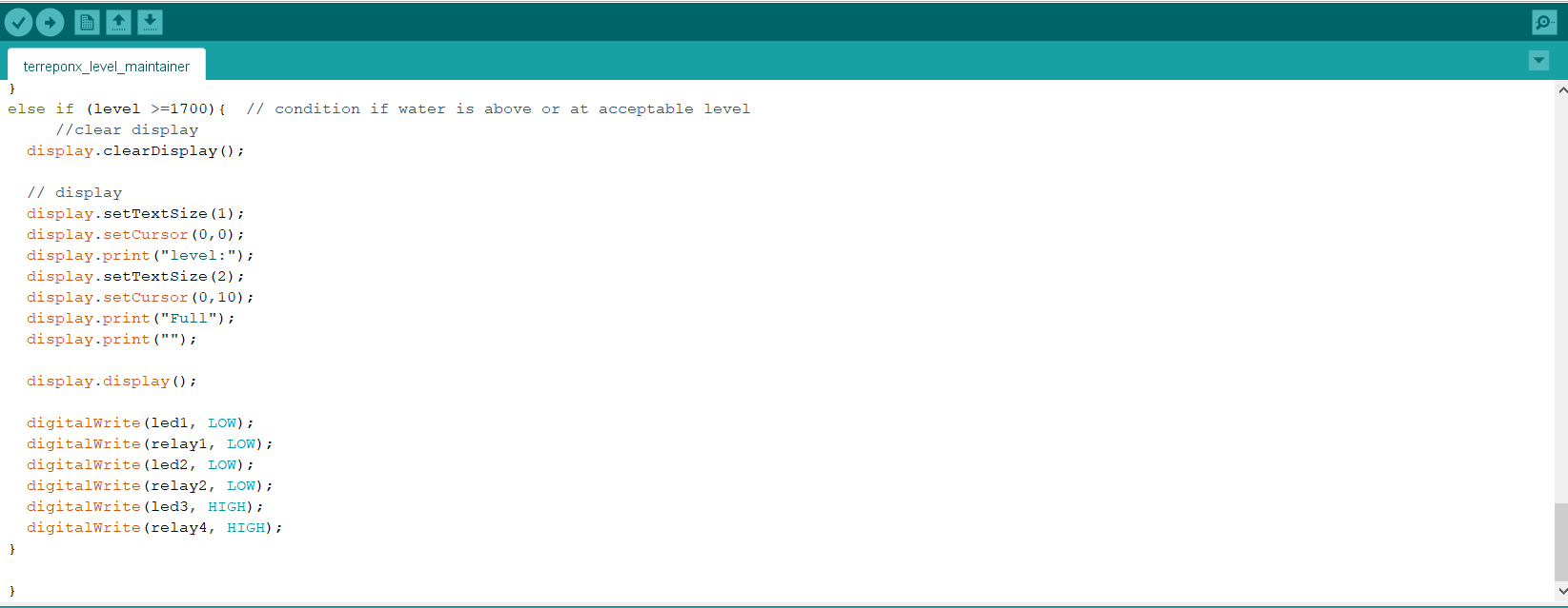
else if (level >=1700){ // condition if water is above or at acceptable level
//clear display
display.clearDisplay();
// display
display.setTextSize(1);
display.setCursor(0,0);
display.print("level:");
display.setTextSize(2);
display.setCursor(0,10);
display.print("Full");
display.print("");
display.display();
digitalWrite(led1, LOW);
digitalWrite(relay1, LOW);
digitalWrite(led2, LOW);
digitalWrite(relay2, LOW);
digitalWrite(led3, HIGH);
digitalWrite(relay4, HIGH);
}
}
I plugged 3 submersible pumps into the controller. One of the pumps represented a main water source, the second pump was placed in another container that represents the fertilizer mix and the third was the pump that would send the water to the plants.