WEEK 12: INPUT DEVICES
For this week we´re going to start first with the individual assignment, so once we´ve got our new boards, my "fabmate" Jon Merino and I, will probe our input devices analogs levels and digital signals for the group assigment.
- For the INDIVIDUAL ASSIGNMENT , my planning will be:
- Add a sensor to a microcontroller board board designed by me.
- Read the sensors data.
- For the GROUP ASSIGNMENT
- Probe our input devices analog levels and digital signals.
INDIVIDUAL ASSIGNMENT
To begin with the individual assignment, we could say that I continued just as I left in week 10, output devices . Just to remember, I finished this week´s assignment exploring and testing a home-made (velostat) force sensor. So, we could say that the natural step is to try to create a step response sensor.
Here´s the video of my home made - velostat force sensor:
To succesfully reach my goal (a functional step response) I started, as every week, doing some research in the step response concept , and reviewed Adrian´s step response from the Adrianino´s collection (thank you!), and also Robert´s Hart, explanations and Neil´s Gershenfeld documentation.
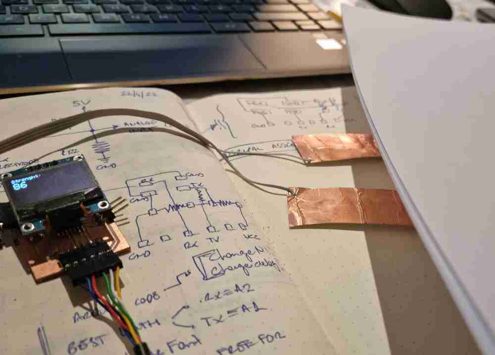
One of my first questions in relation to the step response is related to the microcontroller pins to use, so the first thing I do is review the pins i´ve got to use to make the step response work in an ATtiny1614. After reviewing the above mentioned repositories, it seems I only need an analog input pin (.Rx), and an digital output pin (Tx) and, in my case, I´m going to use two 1M resistors too with a 4 pin cable to board connector, also connected to two copper foil tape electrodes.
For a first spiral I replicated Adrián´s step response by milling his interior and traces .png files. Here you can see how it went:
 Adrián´s step response milled.
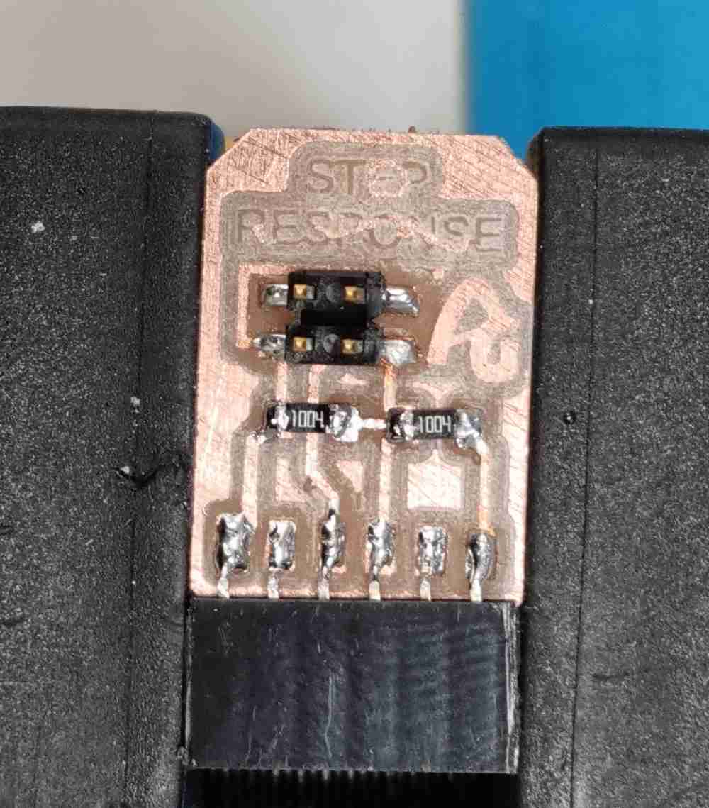 Step response stuffed.
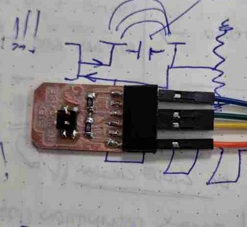 Final result.
Once soldered, I also used the 4 pin cable to board connector, and two copper foil tape electrodes. I connected the 4 pin cable to the step response module, and attached the Tx and .Rx cable to the copper electrodes, one cable to each electrode with a little bit of solder in order to ensure a good conectivity.
Once i´ve got my brand new Adrianino´s step response, and even do I could probably could make it work with the last board I made in week 10, I preffer to create a new board, using again an ATtiny1614, with the specific pins for the step response, following Adrian´s example, and also having the oled display module to view the results, this way, I can continue developing my final project.
This new board, with an ATtiny1614 microprocessor, is very similar to the last board I designed at the output week assignment, but I made some changes to adapt it to the step response and the Oled display module:
| Microcontroller pin: RX (6(PB3)): Connected to TX (Ftdi)). |
| Microcontroller pin: TX (7(PB2)): Connected to Rx(Ftdi). |
| Added two more pins to the FTDI connector: PA5 and PA6 to connect with the step response. |
| Microcontroller pin: UPDI (10(PA0)): Connected to UPDI pin of the hello serial adapter. |
| Microcontroller pin: SCL (9(PB0)): Connected to SCL (Oled module). |
| Microcontroller pin: SDA (8((PB1)): Connected to SDA (Oled module). |
| Added an extra 4 pin connector with: PA2 and PA1 free pins, with VCC and GND. |
| GND: Connected to all the components. |
| VCC: Connected to all the components. |
| CAPACITATOR: Connected between VCC and GROUND, close to the microcontroller. |
| 4.99K Resistors: Between SCL connection and SDA connections and VCC. |
As in the other electronic weeks , I used again EAGLE to do de schematic and PCB design, once done, with the help of modsCE, also as in previous weeks, I prepared the .rml file to be ready to use in our Modela MDX-40A.
Here you can check some images of how it went:
 Schematic design.
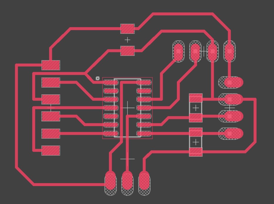 PCB design.
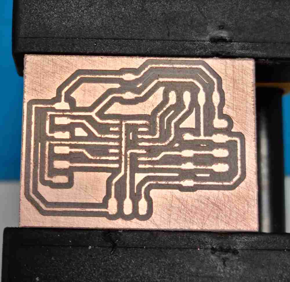 Milled board.
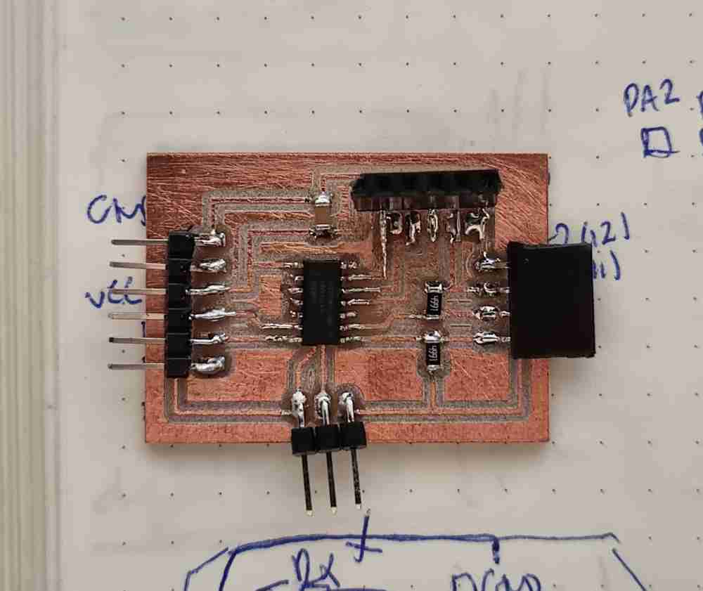 Final board.
Download eagle files: Eagle schematics and pcb. Download board png files: Board .png files.
As for how it´s going until now, everything´s working quite well even do it´s not my best board.., you definitely realize how much you´ve learnt in the last months, and what it felt as a incredible steep high learning curve, you now feel the confindence and the experience of having done this many times in the last weeks. So, we´ll see how it goes from now on..
Now that i´ve got all the "hardware" ready, it´s time to connect it all an program it to see if it works. For this step, i´m going to use arduino IDE to program my board, with the aim of visualizing the outcome data in the serial port and in the oled display module at the same time.
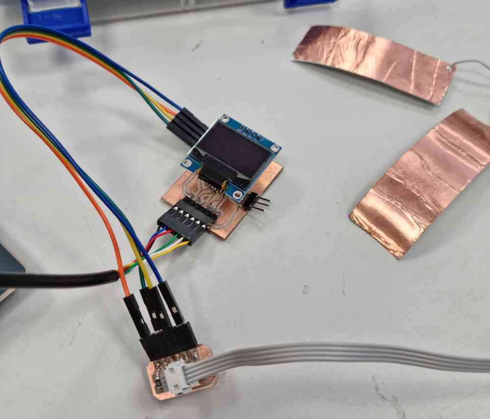
 Step response and pcb connected.
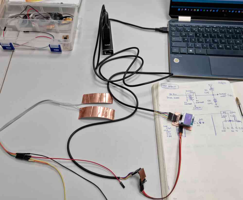
But before jumping into the arduino IDE, and applying all I learnt from Arduino IDE in output week, I reviewed the code and the program used by Adrián, Robert´s Hart, and Neil´s Gershenfeld. After checking them all, I planned to use Adrián´s code with the following modifications:
- Used different pins for .Rx(A2) and TX(A1).
- Used digitalWriteFast.
- Added all the code related to Oled display module visualization.
Here you can see the code used:
Download .ino file: Arduino step response + Oled display.ino
Once I confirmed that it worked properly, I did some tests changing from digitalWrite to digitalWriteFast, changed N (number of samples to take) and the delay, finding the best results in the code shown before.
Here you can see the difference with digitalWrite versus digitalWriteFast
digitalWrite
digitalWriteFast
Even do it seems that it needs a little bit of improvement, it works!. At the end, I had to change pins to PA1 and PA2, not being able to use the ones on Adrián´s example, due to the fact that if I use them I can´t see the results on the serial, because its the same pinout. But, as I made a board with two extra analog and digital pins, I used them instead (as you can see in the code and videos above).
So, first goal achieved, and excited about it! Now it´s time to continue testing but, as you can see in the next image, I had a little issue with my step response, as it broke while changing electrodes, I literally ripped the copper from the board.
 broken step response.
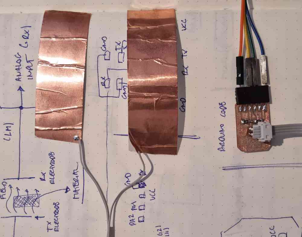
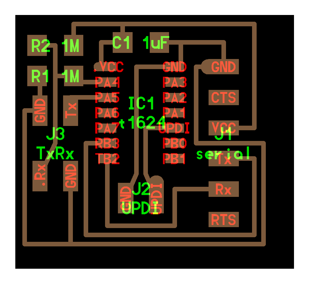
As i´ve broken my Adrianino´s step response, I decided to make another, but this time i´m going to design it by myself. After reviewing again the previous documentation, I noticed that in Neil´s documentation, the .Rx pin is the one connected to the two, 1M each, resistors, but, on the other hand, in Adrián´s step response, the Tx is the one connected to the resistors. I supponse it musn´t have too much consequence, but as Robert Hart diagram clearly shows that the analog input (.Rx) is the one connected to the resistor, that´s what i´m going to make. So, to achieve it, I based my step response in Neil´s ATtiny 1624 board design,
So, after drawing it in paper, I designed the schematic and the pcb in EAGLE, as always, and this are the results. Now, I have to wait until monday (it´s saturday late at night..) to mill my step response and continue testing it.
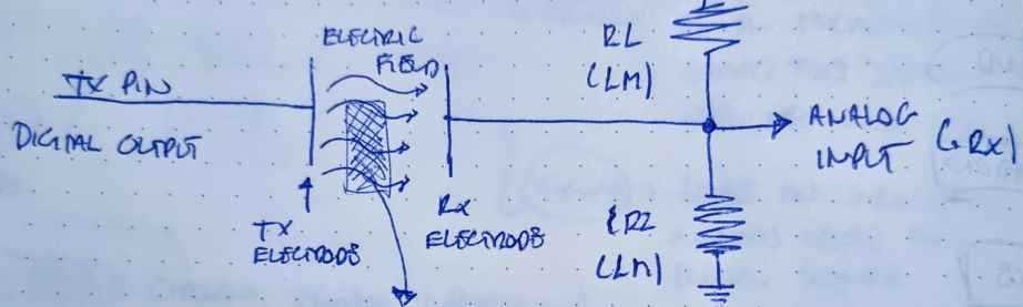 Robert´s Hart diagram
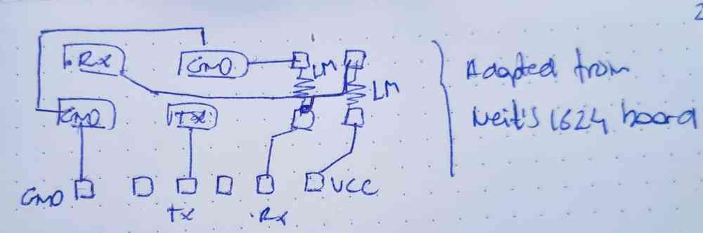 Step response adapted from Neil´s 1624 design.
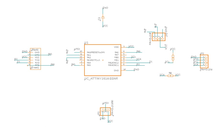
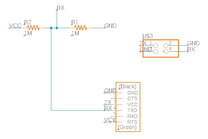 Eagle´s schematic.
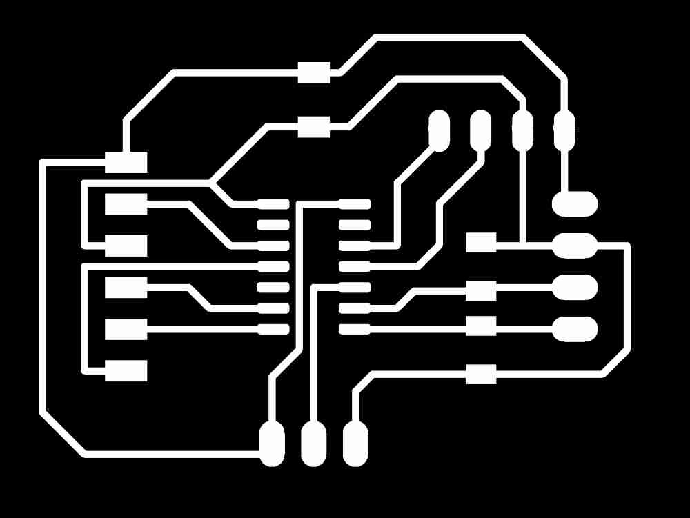
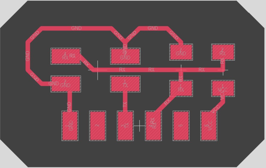 Eagle´s pcb.

Download eagle files: Eagle schematics and pcb. Download step response .png files: step response .png files.
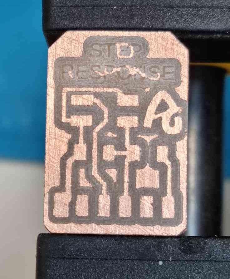
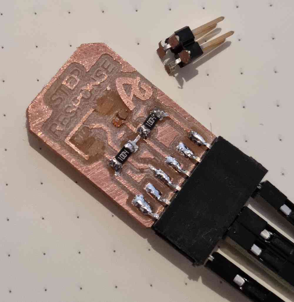
Once i´ve got my eagle design ready, as in previous electronics production weeks, I used modsCE to prepare the .rml file, milled it in our Roland Modela MDX-40 through it´s dedicated program (VPANEL), and soldered all the components needed. Here you can check the results:
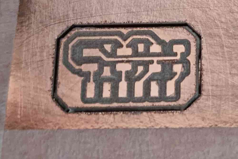 designed step response.
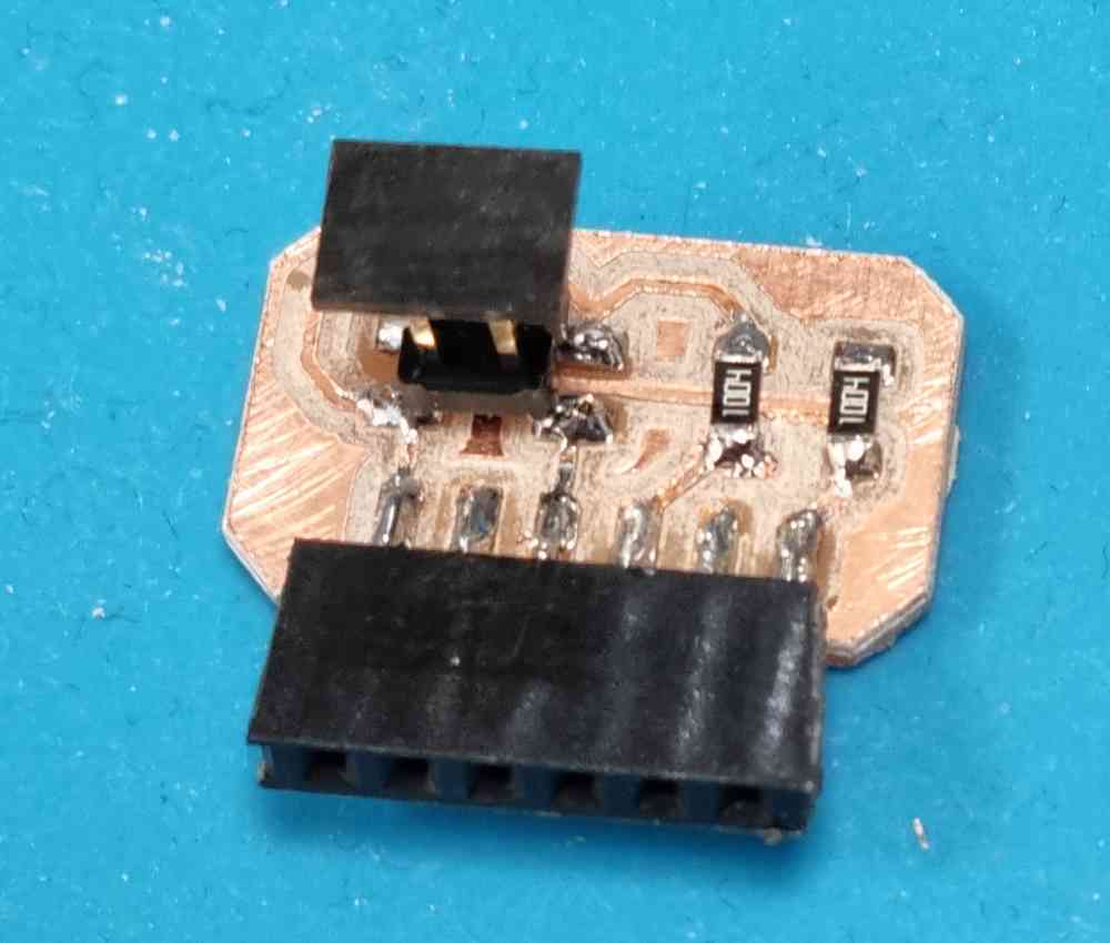
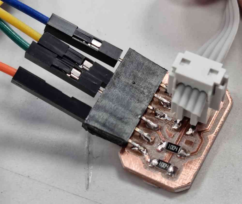
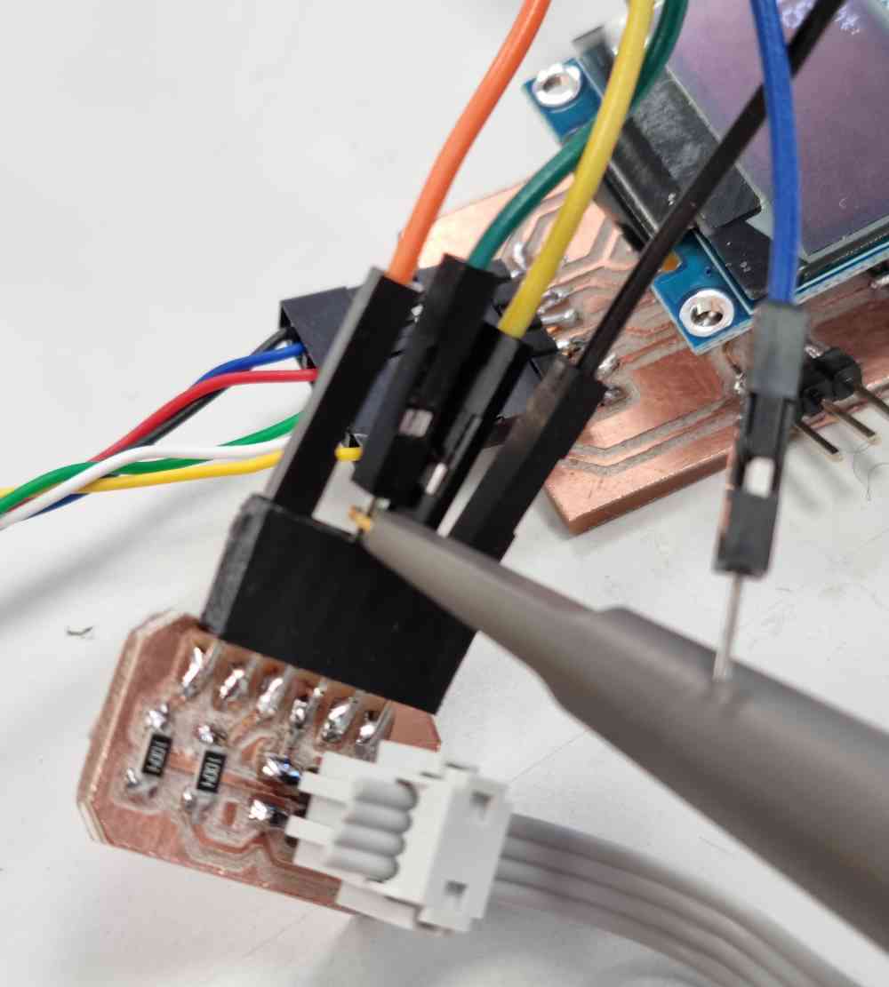
 board + step response.
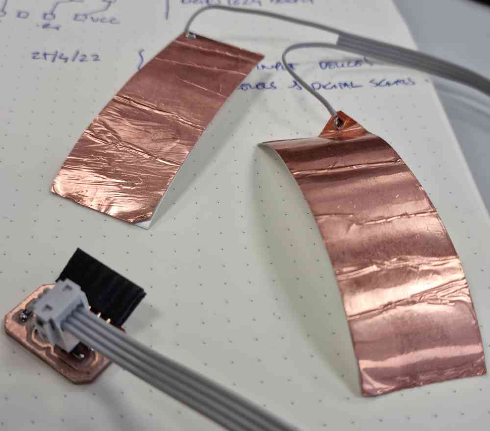
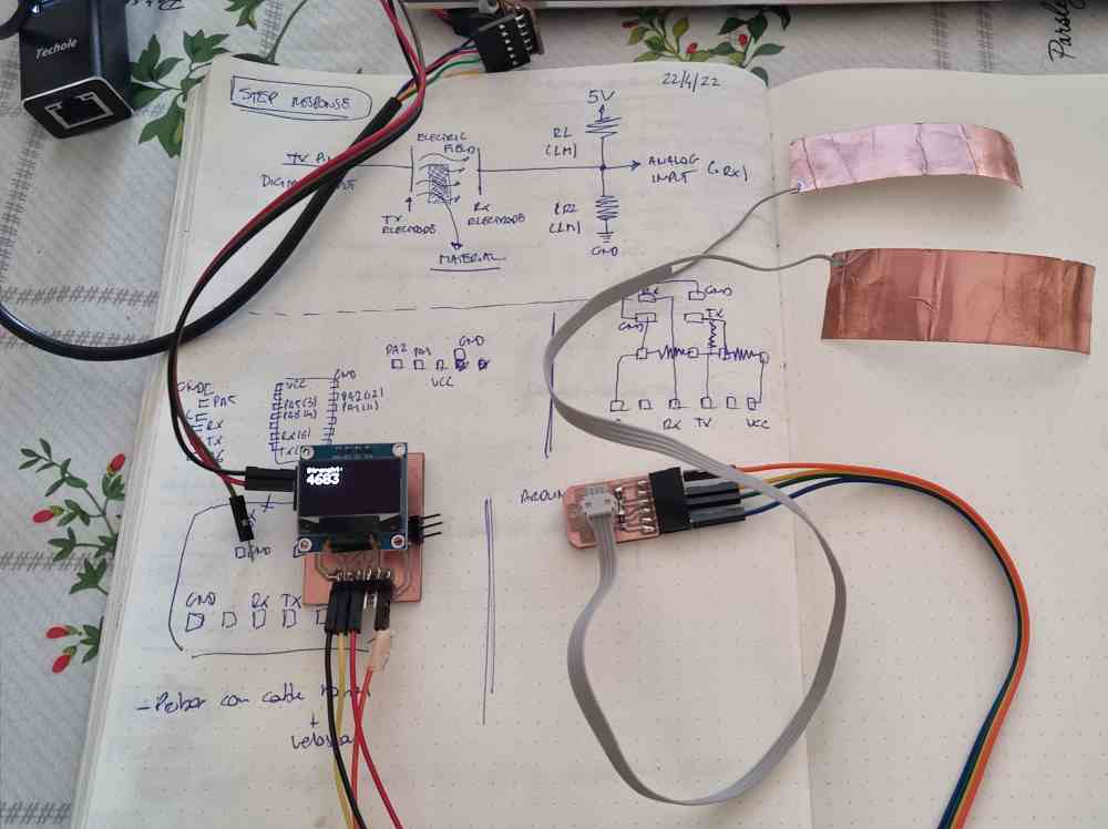
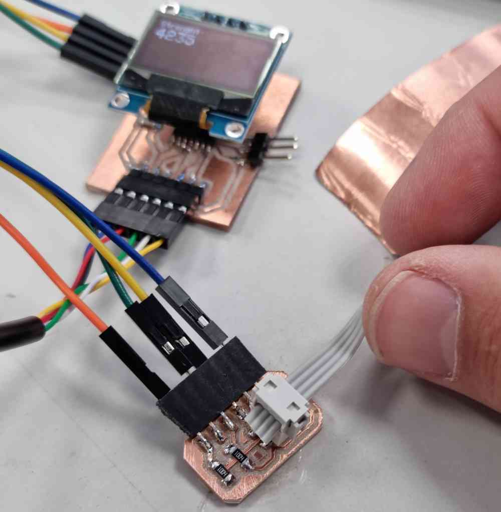
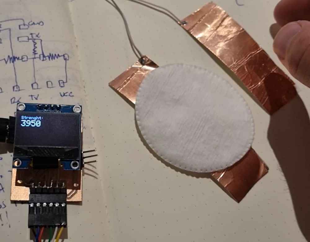
Now that i´ve got my brand new homemade step response, it´s time to try it, using the same code as before I tested proximity, by replicating Neil´s example of putting papers on top of the electrodes and placing my hand above. As you can see in the video, the sensors react to the hands height and horizontal movement position (I´m really amazed with this module!!
PROXIMITY TEST
 proximity test.
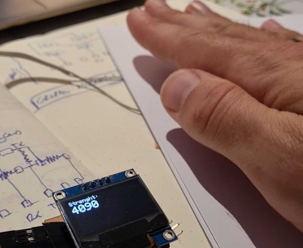
Continuing with my tests, I also replicated the force test done by Adrián. But changing the sponge material by another that I had at hand.
FORCE TESTS
 Force test.
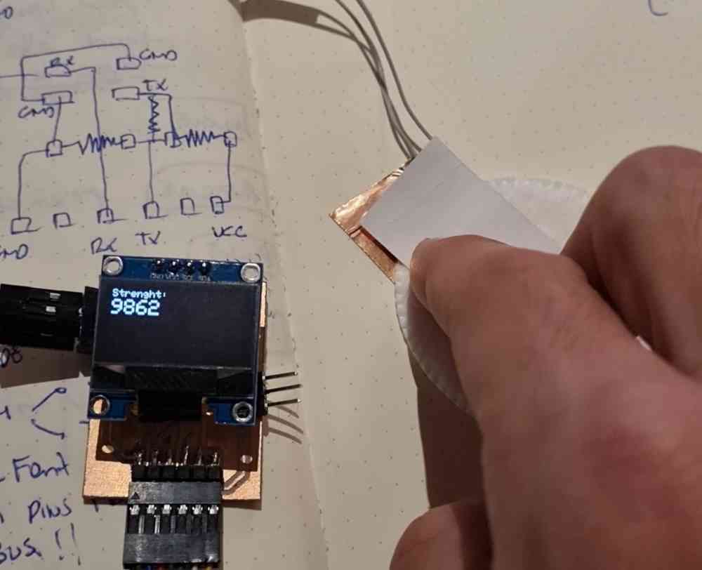
After seeing how well this module/sensor works, i´m definetely going to use it in my final project. As I wanted to explore all the possibilities, I made several tests, FIRST by swapping the copper electrodes for 2 layers of velostat, as i´ve said at the beggining of this assignment, I made a home made sensor with velostat, so now i´ll test how well does it work out, as it might be a more suitable material to use for my final project purpose, as it´s more flexible and durable. To test it, I just changed the copper electrodes for two layers of velostat and gave it a try. But.., unfortunatelly.., it didn´t work out.. The value, insteand of increasing, it just dropped down by half, and changed erractically during the test. I suppose it´s not a sufficiently conductive material, so, discarded!.
AFTER, I did another test by changing the values of the two copper plates in the Arduino IDE code, with the aim of being able to "start" with an initial value = 0. The values used were result=(15000, 90000, 0, 1024).. And FINALLY I tested different copper electrode sizes, to see how it went.
MORE FORCE TESTS
 Velostat unsuccessful test.
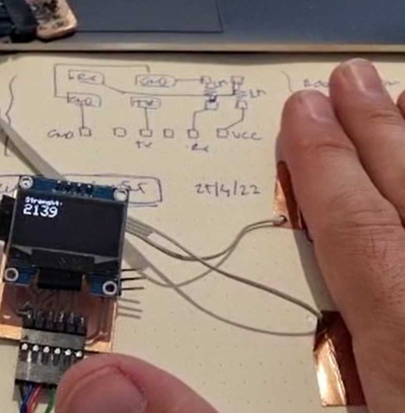 Changing the mapping values in Arduino IDE.
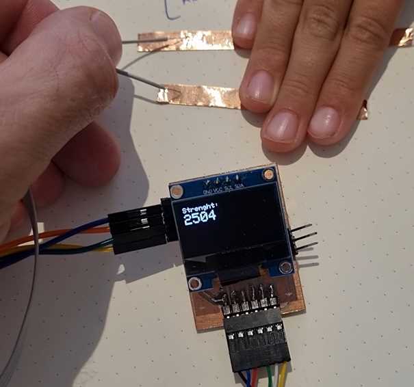 Changing the size of the copper electrodes.
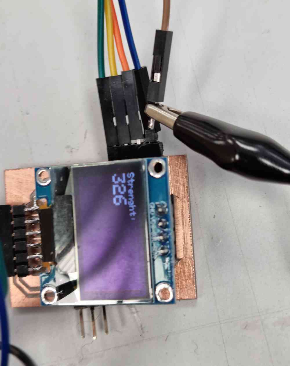
Changing the values of the copper plates in the arduino IDE code, with the aim of trying to start in an initial value=0, it seems like it´s not useful for proximity tests, probably due to the fact that the detection range is drastically reduced, now being only from 0 to about 2.000 units. But, it might be useful for my "strenght" measuring, as i´ve got a stable initial value.. I still have work to do.. but for sure, now I understand much better how the step response works, and I love it!.
LET´S TILT IT!
Finally, I did the TILT TEST, by adding two "rings" of copper aroung a small water bottle, partly filled, at different heights, following Robert Hart´s Tilt sensor image . And surprisingly it works really well! I modified the previous arduino IDE code, and now, when the water reaches the upper copper ring, the result value in arduino CODE turns positive, so at that moment it prints out in the OLED display: OOOPS IT TILTED!. If the water only reaches the lower copper ring, the value is always negative, and nothing will be displayed. So, happy with this extra credit test!
Download .ino file: Arduino Tilt step response + Oled display.ino
Here you can check some images:
TILT TEST
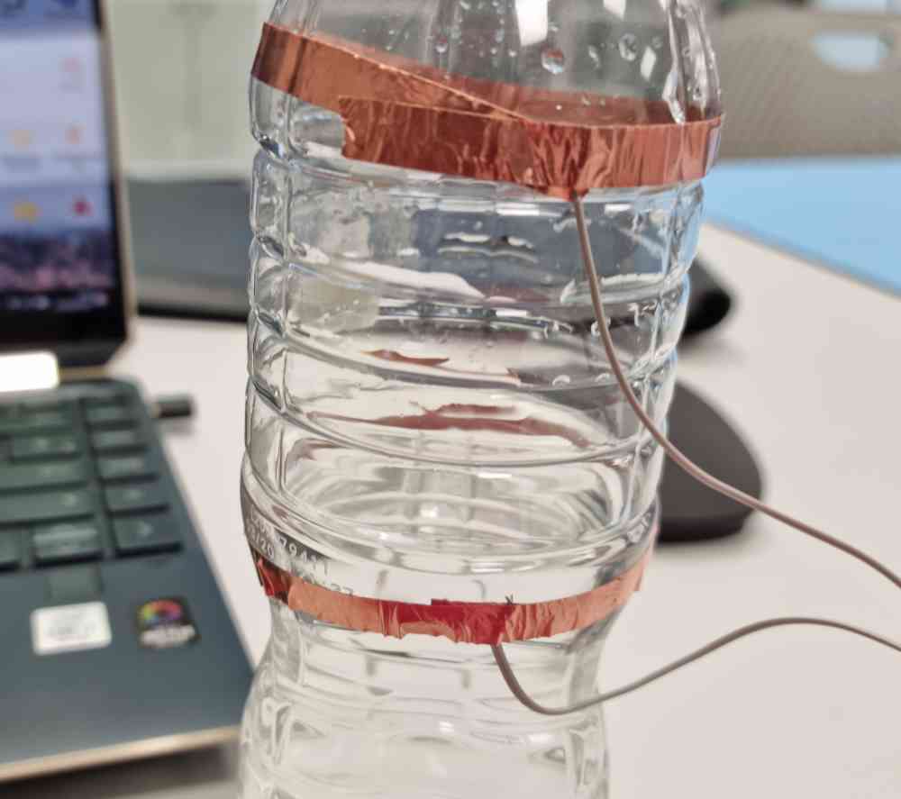 Copper circles.
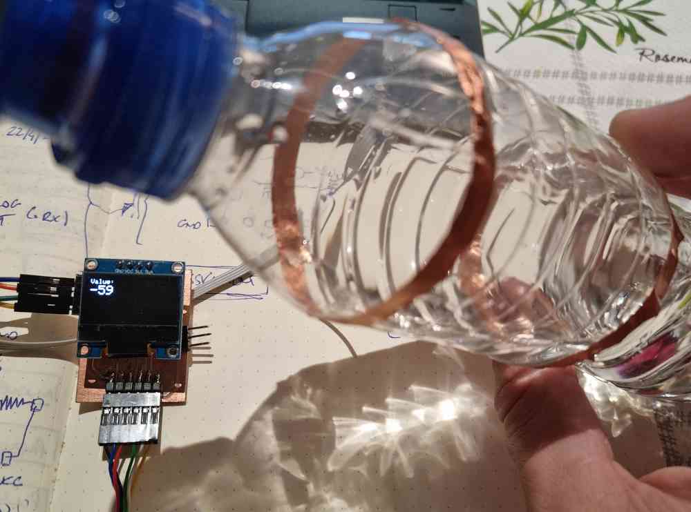
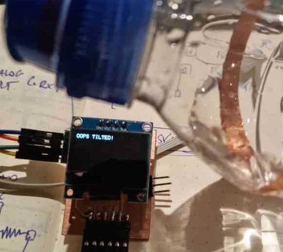 OOPS IT TILTED!
GROUP ASSIGNMENT
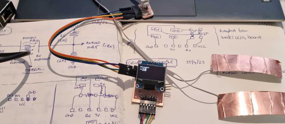
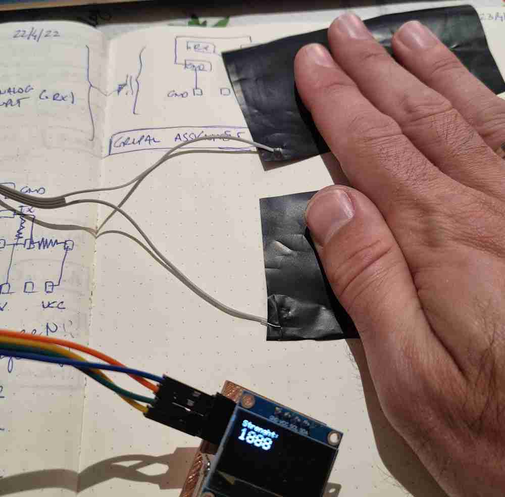
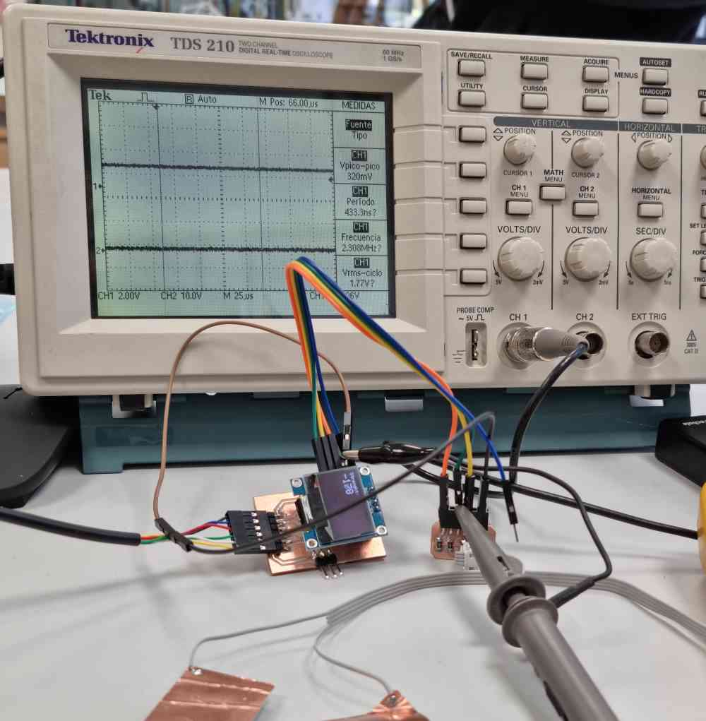
For the group assignment, we need to probe our input device analog levels and digital signals, so in my case, I measured the values of my board with my step response module. In order to do it, we used, as in electronics design assignment our Tektronic TDS 210 Oscilloscope.
This time, to be capable of measuring our levels, we connected the oscilloscope probe to the .Rx pin, and ground to ground, as you can see in the following images.
And once everything is set, we visualize our modules values as you can see in the next video.
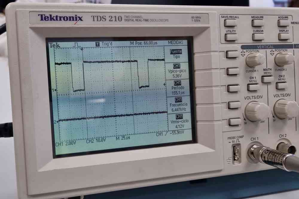
So, for our step response module, the values obtained were:
- 2.5V of medium voltage in continuous
- A maximum of 5V with peaks of 2.5V at each side.
- 125 microseconds upwards and 25 microseconds downwards.
Finally, you can check what my fabmate Jon Merino measured in his input device, as the second part of our group assignment.
Back to top