WEEK 10: OUTPUT DEVICES
For this week we´re going to start first with the individual assignment, so once we´ve got our new boards, my "fabmate" Jon Merino and I, will measure the power consumption for our group assigment.
- For the INDIVIDUAL ASSIGNMENT , my planning will be:
- Select and review the data sheet of my output device and the microprocessor that i´m going to use.
- Design, mill and stuff the new board.
- Program it to do something.
- For an extra spiral (if possible): test outputs for my final project.
- For the GROUP ASSIGNMENT
- Measure the power consumption of our boards.
INDIVIDUAL ASSIGNMENT
To begin with the individual assignment, first of all, after preparing this week´s work with my instructor Alberto, I decided to use for the first time an ATtiny1614 microprocessor, as it seems that it´s suitable for what I want to do for my final project. So, first of all I check the pinout and the data sheet to understand how i´m going to design my board. The most important feature, when comparing it with the ATtiny45/44 is that it´s got a UPDI pin, so we can program the processor through it, having no need to use ISP.
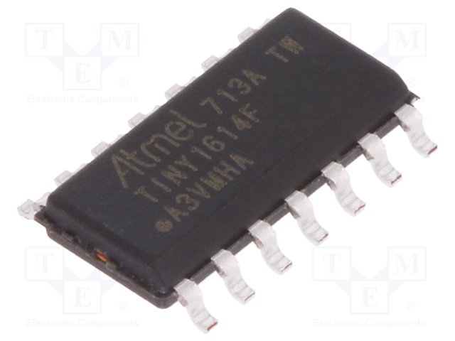
- 14 pins.
- 2Kb of SRAM.
- 16 Kb of FLASH.
- 256 Bytes of EEPROM.
- 20MHz of max frequency.
For a first spiral, I want to use the OLED Display Module with the SSD1306 Driver so, I also checked the data sheet, and its pinout. The good thing about this module is that, thanks to the electronics that´s inside, using the SSD1306 controller it can be powered with a 3.3V or 5V supply.
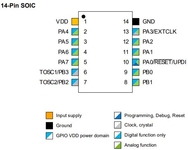 ATtiny 1614 pinout.
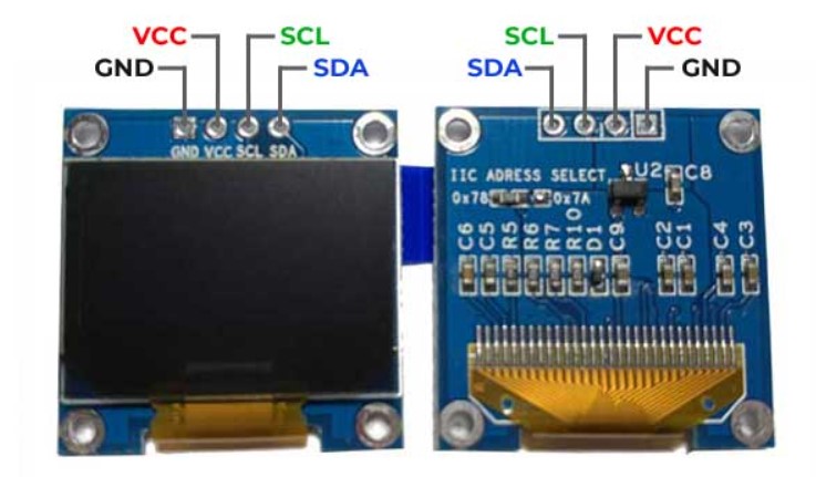 Oled module and pinout.
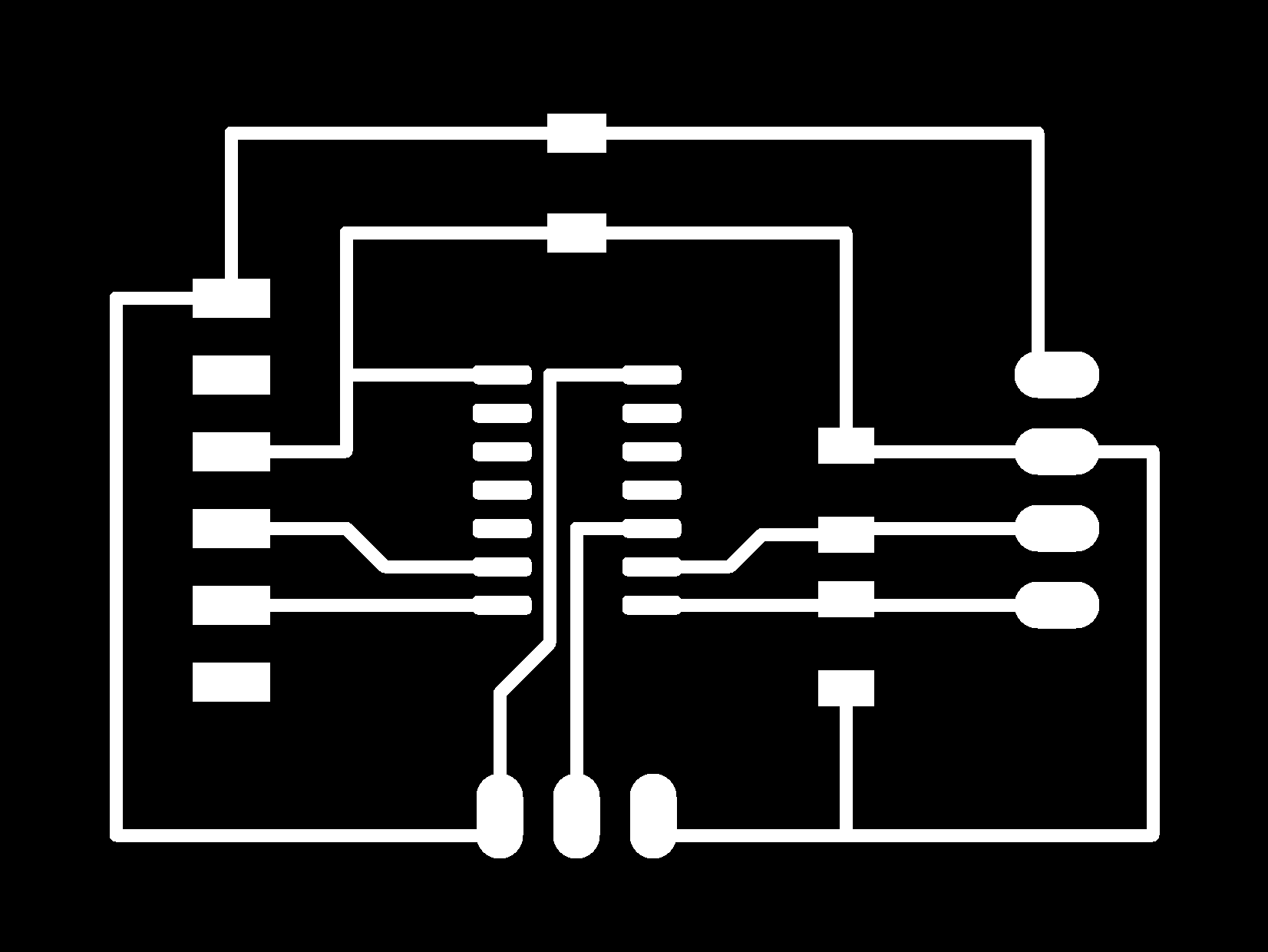
After reviewing all the information. I and made a first skecth of my board including and the components needed and the design rules:
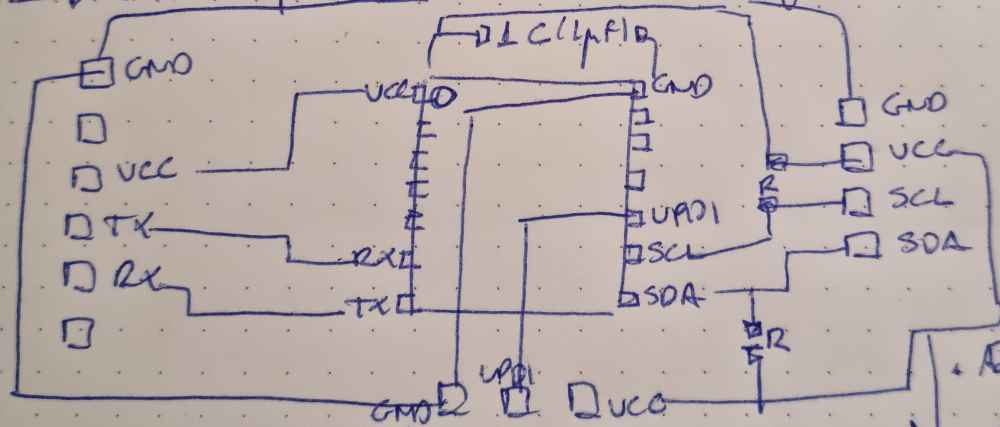
| Microcontroller pin: RX (6(PB3)): Connected to TX (Ftdi)). |
| Microcontroller pin: TX (7(PB2)): Connected to Rx(Ftdi). |
| Microcontroller pin: UPDI (10(PA0)): Connected to UPDI pin of the hello serial adapter. |
| Microcontroller pin: SCL (9(PB0)): Connected to SCL (Oled module). |
| Microcontroller pin: SDA (8((PB1)): Connected to SDA (Oled module). |
| GND: Connected to all the components. |
| VCC: Connected to all the components. |
| CAPACITATOR: Connected between VCC and GROUND, close to the microcontroller. |
| 4.99K Resistors: Between SCL connection and SDA connections and VCC. |
For the second step of my individual assignment. I´ll use EAGLE again, as in the other electronics assignments ( electronics design). It looks like that EAGLE from fusion 360 has been updated, and some things have changed, such as the design manager of the shematic document, but, after a while familiarizing with the new interface, it all worked well, and it seems that the syncronization problems that I had on the embbeded programing week have been resolved. The only thing you have to take into account is that the ATtiny 1614 component view in the schematic document is different from the PCB document, but it´s sorts out well. Also, that you won´t find 1x4 and 1x3 pinheaders in the fab library, you´ll have to find the on the other libraries. You´ll need to use the PINHD-1x../90, and be aware that when exporting the image, they are set on the pads layer and not on the top layer. The only way to have all the pads in the same layer is by "filling" these pinheaders manually with 50 or 60 point trace width.

COMPONENTS NEEDED
- Capacitator: CAP_UNPOLARIZEDFAB x1.
- Resistors: R1206 (2x 4.99K).
- 1x4 PinHead: PINHD-1X4/90.
- 1X3 PinHead: PINHD-1x3/90.
- UC_ATTINY1614 x1.
- Connector: 06_FTDI_SMD_HEADER x1.
Here you can check some images from the EAGLE DESIGN PROCESS:
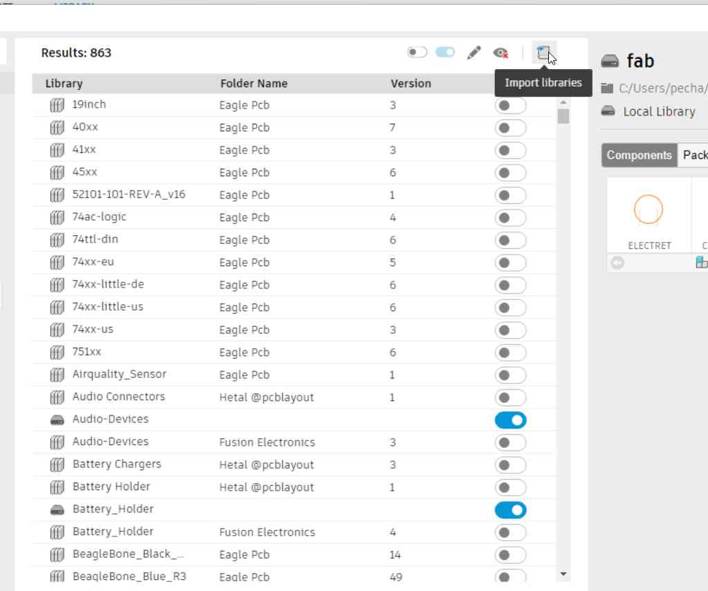 New library interface.
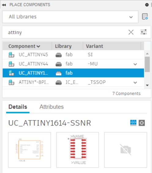 New place components.
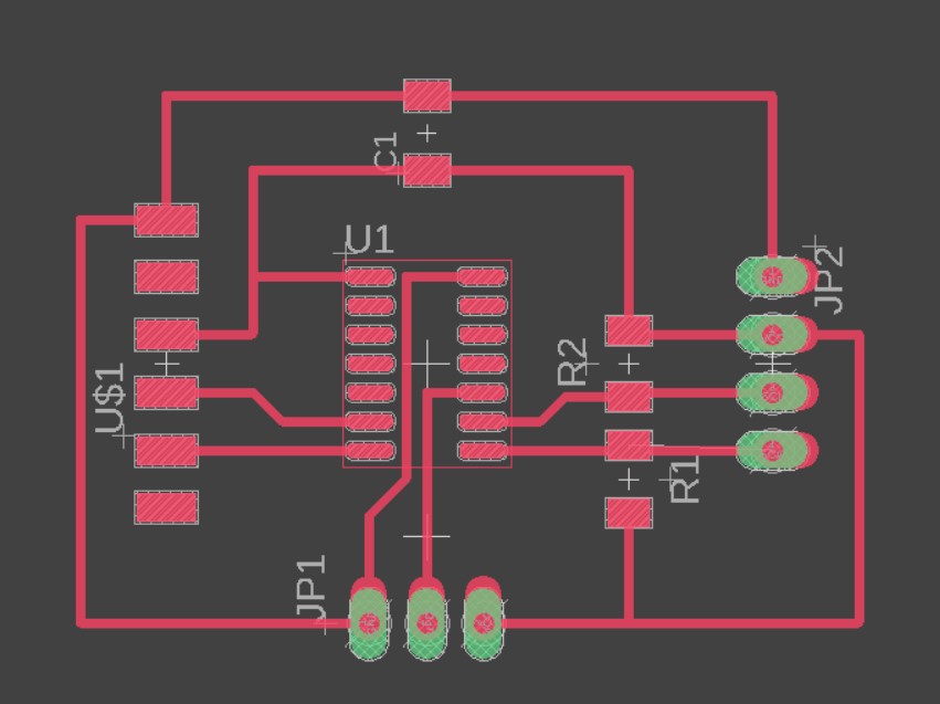
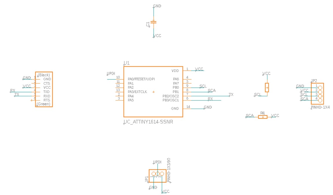 PCB schematic.
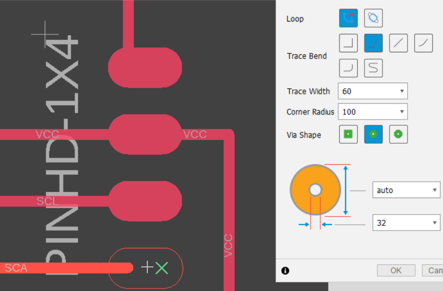 "filling" the pinheaders.
Download eagle files: Eagle schematics or Eagle board.
Once the design was ready, I opened it in ModsCE and to my surprise, MODSCE has changed too! Now, you can only set the PCB defaults in inches, and not in mm. It really is not an issue, because you can add the values in mm in the in mill raster 2D, but you have to be very careful and change all the values. In my case I nearly forgot to change the offset number when changing from traces to outlines. And also, outlines don´t have offset stepover, so you also have to change that value to 0. So, if I had to do it again, I would set the offsets and speeds in the set PCB defaults, and after in mill raster 2D, I would have changed the tool and cut paramenters to mm. But, apart from that, everything went well.
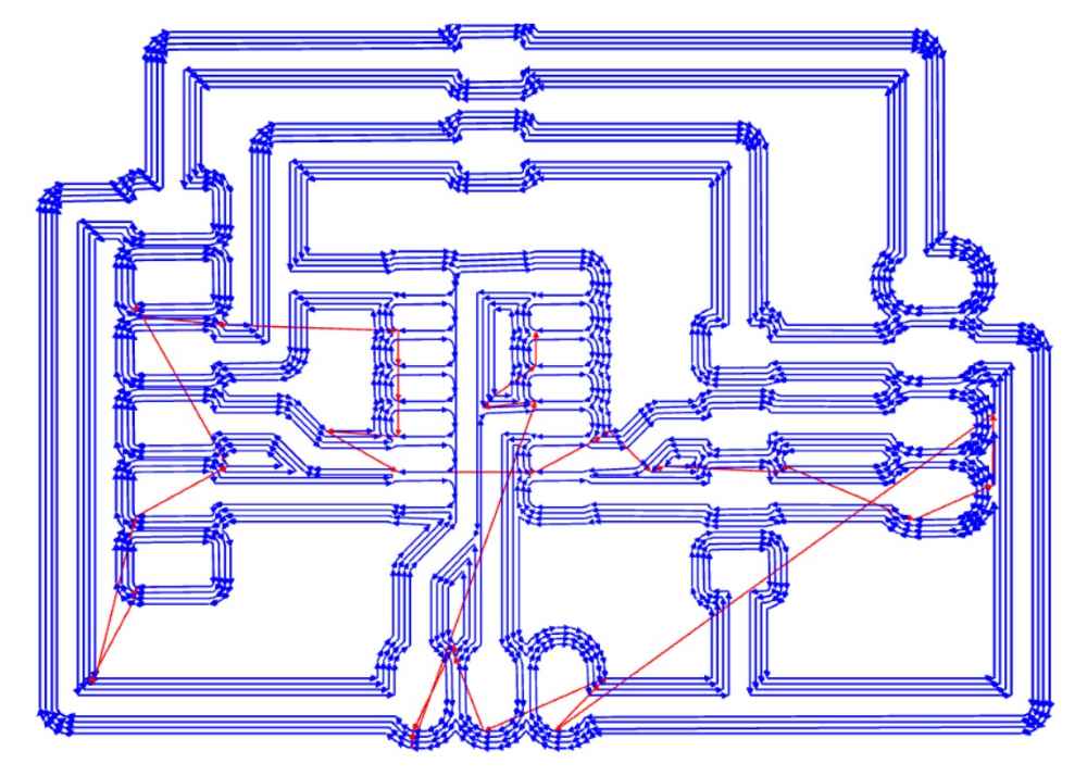 Traces toolpath.
 Outline settings.
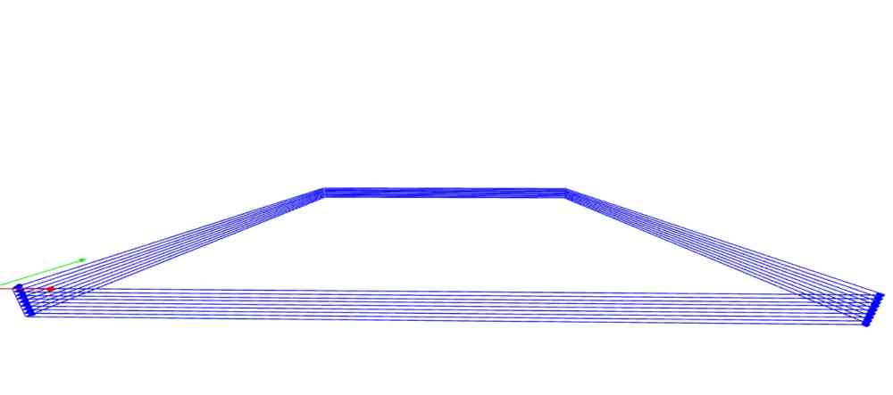 Outline toolpath.
Download .png files: Outputdevicetraces.png or Outputdeviceoutlines.png.
Once I had the pcb design ready to mill. I used our Roland Modela MDX-40A as in previous assignments. This time, in order to improve the milling performance, I followed the regional review recommendations: I used double sided tape, and placed the board where the base of our Roland Modela was less used, and definetely got the best results so far! So, happy with how things are going until now. No big issues and having the feeling that i´m improving my skills and therefore my final results:
 Final PCB design.
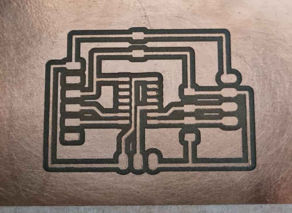 traces milled.
As you can see in the image, traces are cleaner than ever, and without a sign of erosion. Definetely the double sided tape has reduced vibrations and has avoided the effects of bent PCB´s minimizing the risk of breaking tips.
Now, it´s time to stuff our board with all the components. Soldering went good, had no issues with it, the only issues was that we ran out of some certain types of pin headers in the lab, and had to improvise with different types, and finally, as always took my time and checked all the connections after finishing.
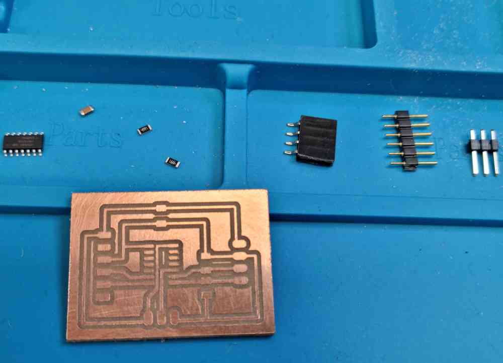 Components to solder.
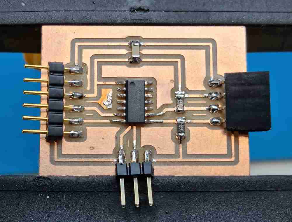
Afer soldering.
The last, and most important, part of the individual assignment is to program our board to let the OLED do something. I say it´s the most important because it´s where we have to do something new this week. So, I started reviewing some repositories, and followed Sergio Herranz´s, because he used the same microprocessor as me with the OLED module. As I already had installed and configured my arduino IDE to work with ATtiny boards (board manager and libraries), as you can check in electronics design, I just had to set my arduino IDE to work with the ATtiny1614 processor and add the specific OLED library.
So, to make the OLED "do" something, this are the steps I took:
| Go to TOOL -> Boards -> Board manager: Search for MegaTinyCore from Spence Konde and install it. |
| Select from the MegaTinyCore the ATtiny 1614 board. |
| Edit the settings of the ATtiny 1614 board: I just followed Sergio Herranz settings from his repository. |
| Go to SKETCH -> Manage libraries -> Include libraries: Install Adafruit_SSD1306 library. |
| Check that you also got the following libraries: Adafruit GFX, and Wire (I had them both in my arduino IDE library). |
| Connect your board and serial updi to an USB adapter, and both to your board: I had to create my own SERIAL UPDI+VCC converter following Adrian´s Adrianino´s design. |
| Connect your OLED module to your board. Check that all connections are properly connected! |
| Load your code to test if it works: For this first test I used a similar code that Adrian´s Adrianinos OLED test, but added a 2 second delay to let the OLED time to initialize and cleaning the display buffer. |
| Select in TOOLS -> the programmer to use: In my case, I used the first SerialUPDI - FAST: 4.5V + 460800 BAUD. |
| UPLOAD: In my case, it only works if I first burn bootload, and after upload directly. |
Regarding programming the Oled module with an ATtiny1614, the only issues I had to work out is the programmer used to upload the Arduino IDE code, and the steps to do so. In my case it only works if I first burn the bootloader and after, in sketches, I upload directly the arduino code (I doesn´t work if I upload it using a programmer). I have to be very careful because I have to change ports between these two steps! I need to work on that to really understand why I have to do it this way. I´ve very little experience in programming so I lack of knowledge, the only difference I find when comparing it to programming the ATtiny45 or 44, is that I used programmers with no bootloader and with the ATtiny1614 there´s only a programmer with optiboot to select..
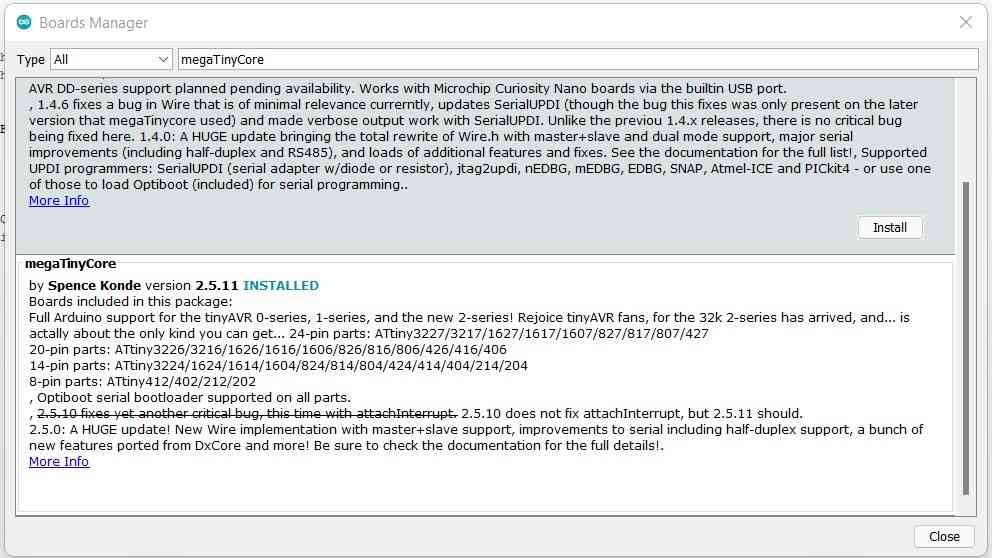 MegaTinyCore board.
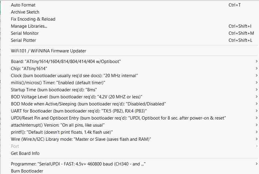 1614 board settings.
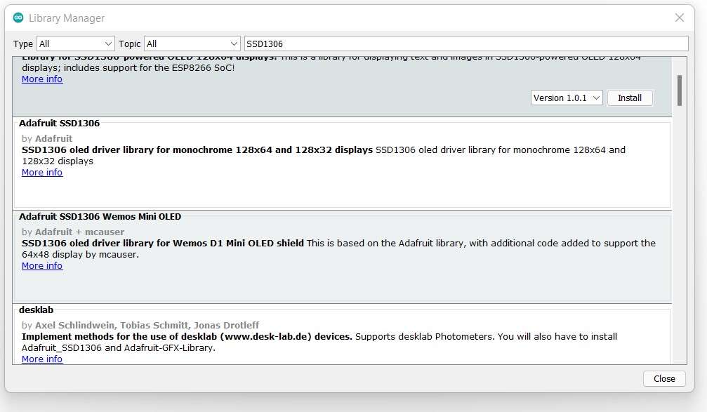 Adafruit SSD1306 library.
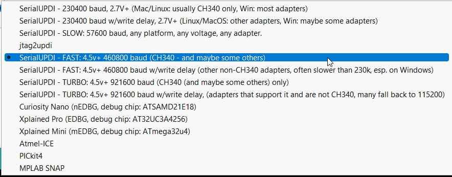 Selecting programmer.
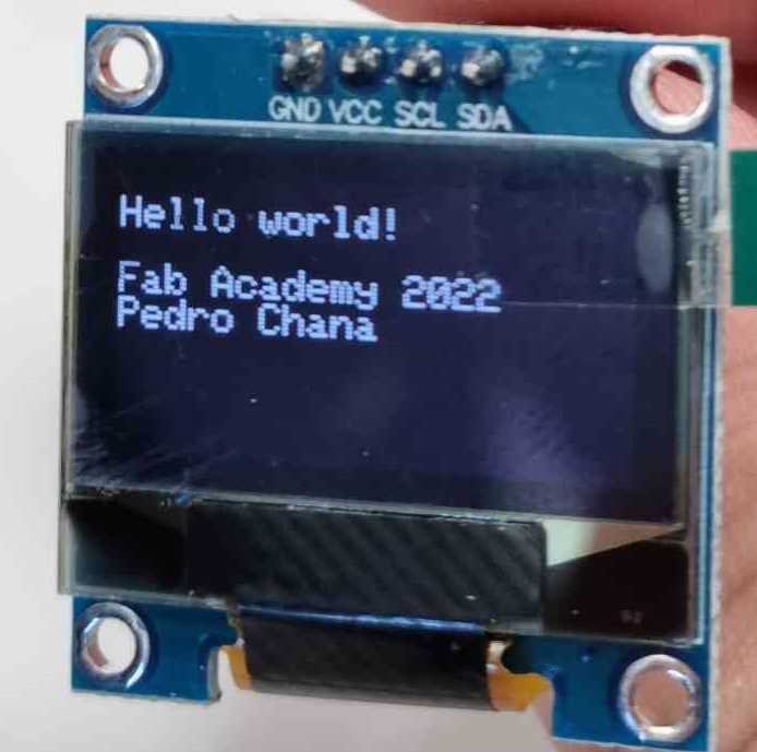
For the first test code, a Hello World static test, I followed the structure below:
| Code | Description |
|---|---|
| display.clearDisplay() | All pixels are off. |
| display.setTextSize(n) | set the font size, supports sizes from 1 to 8. |
| display.setTextColor(n) | Set the font color. WHITE sets white font and black background. |
| display.setCursor(x,y) | print the characters at location x,y. |
| display.printIn("TEXT HERE") | prints the written text. |
| display.display() | call this method for the changes to make effect. |
Here you can see the sketch in arduino IDE:
Download Hello Oled .ino
Now that i´ve got my OLED running, I explored different programming possibilities, in arduino IDE, with the help of this super complete guide. That explains step by step how to code using the Adafruit SSD1306 library in arduino IDE.
FOR SCROLLING TEXT: We just have to slightly modify the text code, adding:
| Code | Description |
|---|---|
| startscrollright(0x00, 0x0F) | Scrolls text from left to right. |
| display.stopscroll() | Stops scrolling. |
| startscrollleft(0x00, 0x0F) | Scrolls textx from right to left. |
| startscrolldiagright(0x00, 0x07) | scroll text from left bottom corner to right upper corner. |
| startscrolldiagleft(0x00, 0x07) | scroll text from right bottom corner to left upper corner |
Here you can see how it looks and the sketch in arduino code:
Download Oled scrolling .ino
Finally, I also practiced viewing an image in my OLED module, I used an Fabacademy .svg image I adapted for the last assignment. In order to do it, I followed the Oled guide I recommended before, but using different program to edit the image. In my case I used GIMP and as recommended the LCD Image Converter. A program that will allow you to create bitmaps and fonts, and transform them to “C” source format for embedded applications. So, This is what I did:
| Open selected image with GIMP or similar program: Adjust image to 128x64 pixel size and convert to monocrome. |
| Save image as .bmp file. |
| Open it in LCD Imaging Converter program. |
| Go to OPTIONS: And change the settings to: Preset to monocrome, Type to monocrome, Threshold dither, Top to bottom, and Foward. |
| In OPTIONS-> select IMAGE: Aplit to rows, 8-bit block size, and Little-Endian byte order. |
| Now, clik OK and go to FILE: Convert to C Source Code. |
| Open your new C file with a Word pad or similar: I used Visual studio code. |
| Copy your code to your Arduino IDE skecth: in display.drawBitmap() you have to paste what´s underneath your C file image bitmap. This is my example: display.drawBitmap(0, 0, image_data_Logofab, 64, 64, 1);. |
| Upload your sketch! |
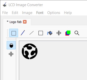 LCD imaging converter.
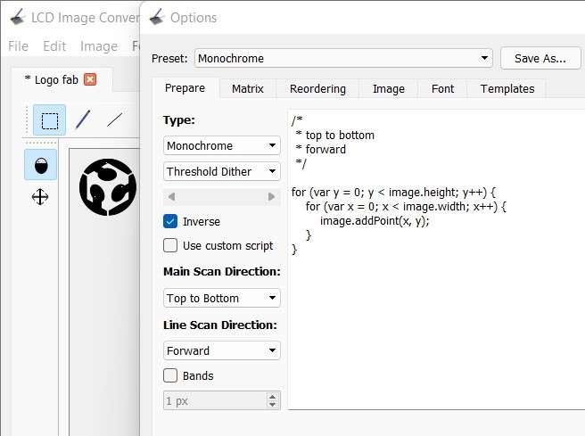 Editing options.
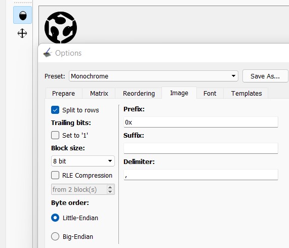 Image settings.
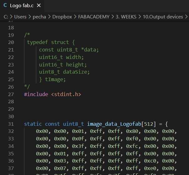 Reading C document.
Here you can see the arduino IDE sketch:
Download Oled bitmap fabacademy .ino
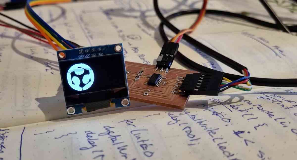
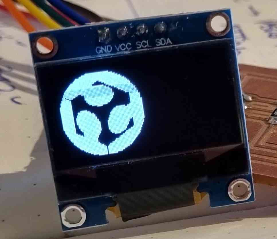
Here you can see the Fabacademy logo example in my Oled module, and in the other image, I inverted colours using display.invertDisplay(TRUE).
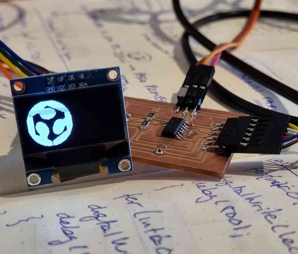 Fabacademy logo.
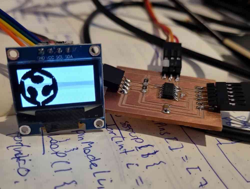
Fabacademy with invertDisplay(TRUE).
GROUP ASSIGNMENT
For this week´s group assignment we have to measure the power consumption of our boards. So, in order to achieve it, we have to obtain our board current and voltage values to be able to calculate the power consumption (P=IxV). So, below you can find how we measured my board, and in my fabmates (Jon Merino) weeks assignment, you can find Jon´s board power consumption.
To measure the current and voltage of our boards, we used our KOBAN KM838 MULTIMETER, as shown in electronics design week. But this time, we used it in two different ways:
- To measure the Voltage.
- To measure the current.
1. VOLTAGE MEASUREMENT: To measure Voltage, we set a high resistance (20m), and measured the value between Ground and VCC with the board connected, and as you can see in the image, it gave us a value of 4.87 volts.
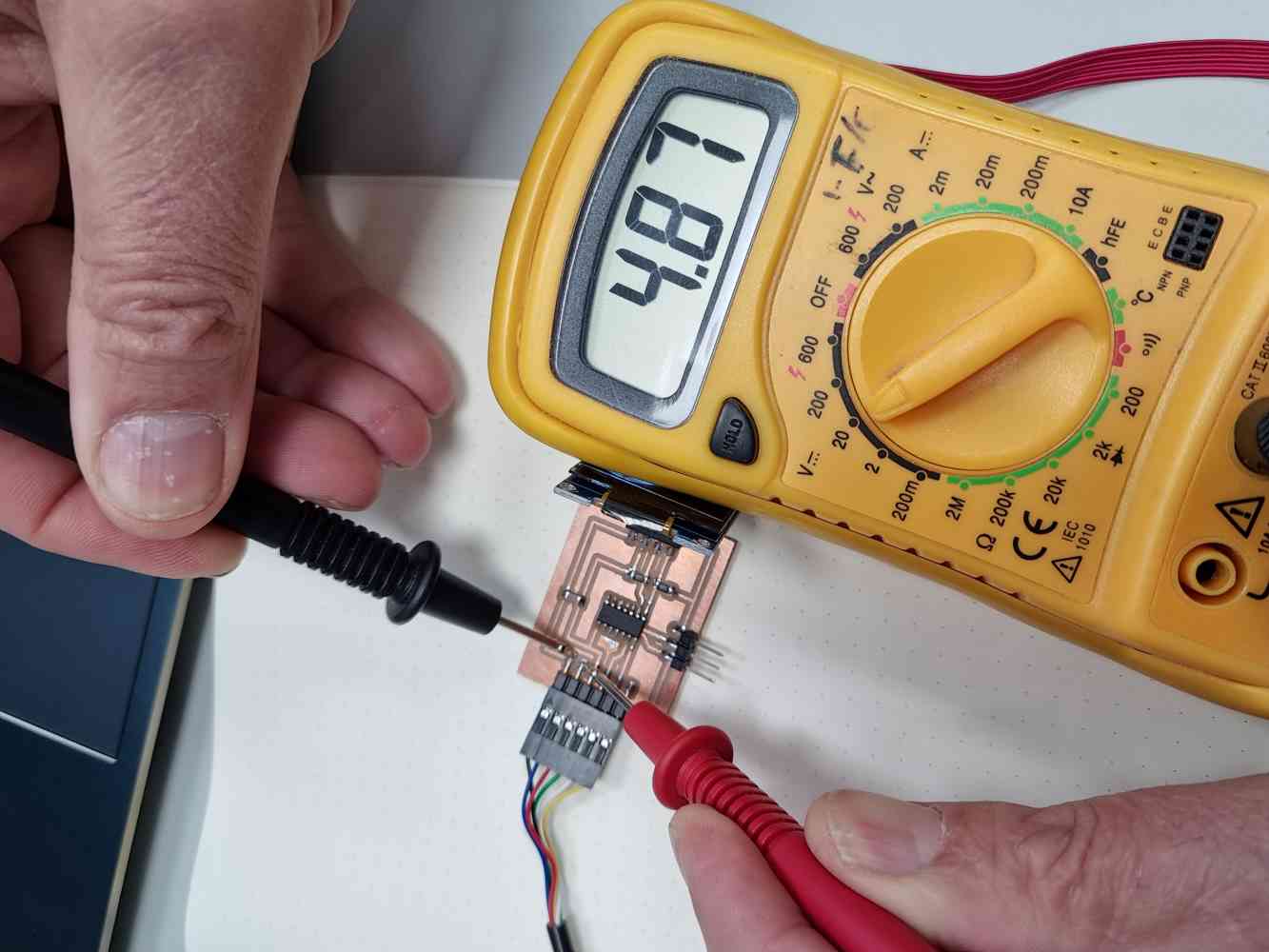 Volts measurement.
2. CURRENT: To measure Current. We have to set the multimeter differently, now the current must pass through it, with a very low resistance. So, we did three different measurements, the first one with the OLED module OFF, the second one with the OLED module ON, and the third one we only measured the OLED´s consumption.
As you can see in the images below, in the FIRST measure with the OLED module OFF we obtained a current value of 3.3 mA (milliampere), in the SECOND measure with the OLED module turned on, we obtained a current value of 21.6 mA, and in the THIRD measure, of only the OLED´s module consumption we obtained a current value of 8 mA.
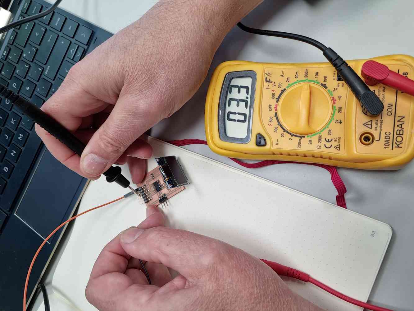 Current with OLED turned OFF.
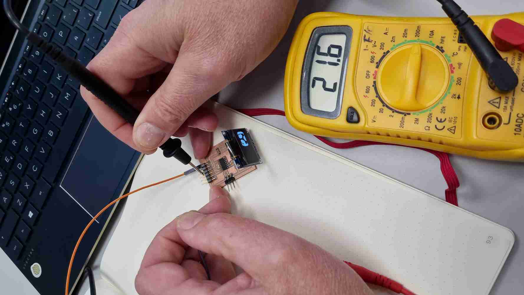 Current with OLED turned ON.
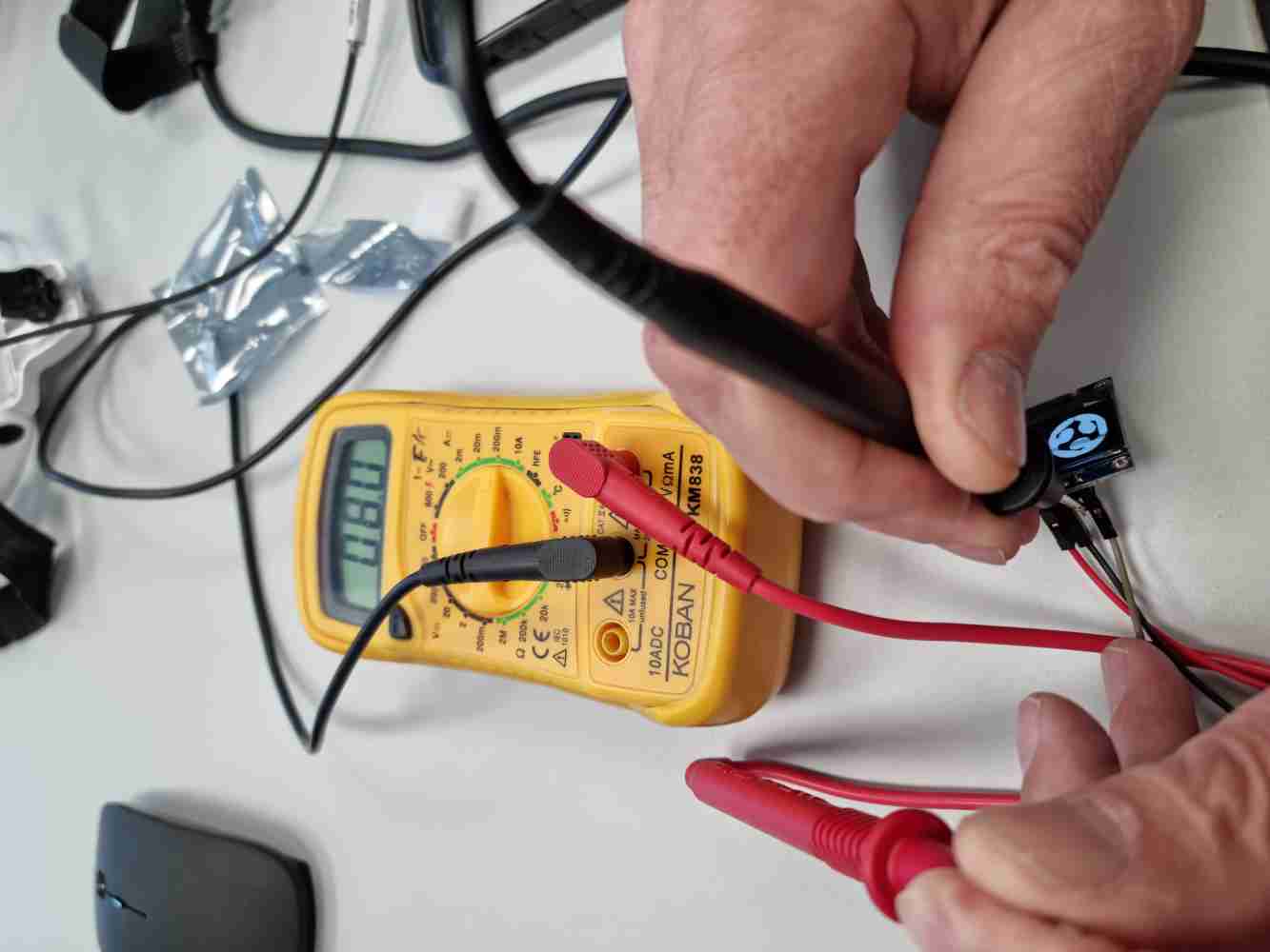 Only OLED´s module.
As you can appreciate in the next video, is very interesting to see how the current varies when passing from the OLED module turned OFF, to turned ON. You can see how the values jumps up to a peak of 24.8A, and then it goes down a little to stabilize in 21.6mA.
Once obtained all the Voltage and Current values, the power consumption results are as follows:
- Power consumption of the board with the OLED module OFF = 4.87volts x 3.3mA = 16.071 milliwatts (mW).
- Power consumption of the board with the OLED module ON = 4.87volts x 21.6mA = 105 milliwatts (mW).
- Power consumption only of the OLED module = 4.87volts x 8mA = 38.96 milliwatts (mW).
EXTRA: TESTING FOR FINAL PROJECT:
As i´ve got some time, I tested how I could use my OLED module for my final project, as I want to visualize the pressure/strenght value that the "patients" perform. In order to test my OLED, I created a second board similar to the one before, but adding 3 extra free-pins + VCC + GROUND. After, I used the same "force/pressure" home made sensor I prepared in the Embedded programming week, created with 2 wires and 4 layers of velostat + a 5K resistor that permits the widest rage of input values.
Once I had the hardware ready and functioning, I prepared the following code in Arduino IDE base on the guide describe before, with the aim of displaying the "pressure" value from my sensor in my OLED module. And after adjusting a little bit the code it works! (I was very surprised to make it work with no too many issues).
Download Strenght display OLED .ino
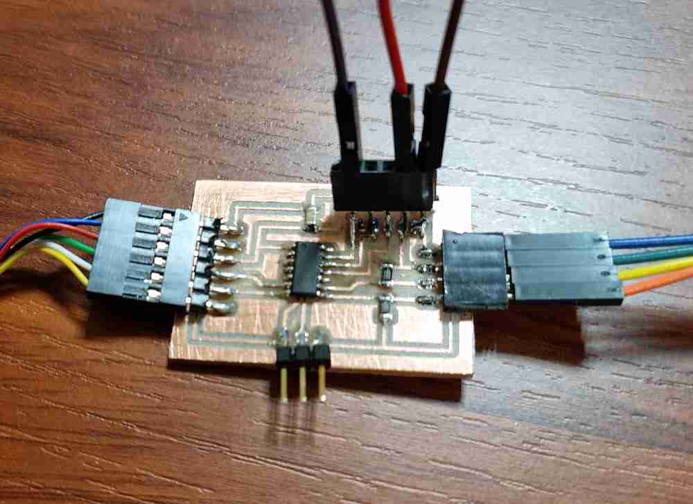 2nd board with OLED + extra pins.
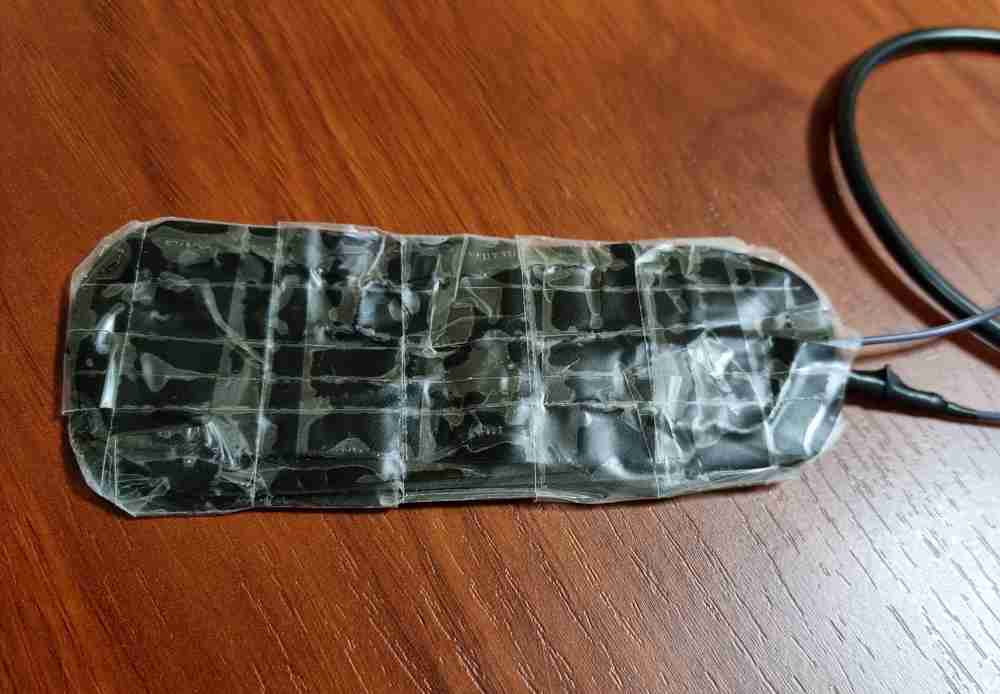 Home made velostat sensor.
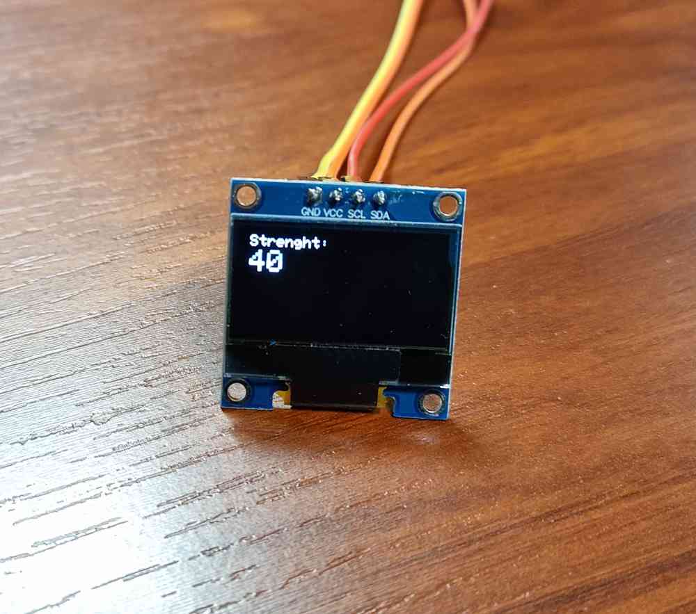 OLED´s "strenght´s value display.
Here you can check how it went:
My next step is going to be to use the step response created by Adrian, but i´ll leave that for the input device week.
Back to top