WEEK 08: EMBEDDED PROGRAMMING
For this sixth group assigment, my "fabmate" Jon Merino and I have to compare the performance and development workflows for other architectures. Usually we work on the group assignment first but, for this week, we´re going to do it differently because the experience that we´re going to gain during the individual assignments will be of great value for the group assignment. So,:
- For the INDIVIDUAL ASSIGNMENT , my planning will be:
- Use my programmer to program by board to do something.
- Read the data sheet of the microcontroller (ATTiny44) that i´m going to use for a second board.
- Design, solder and program a second PCB
- For an extra spiral: Design, solder and program a third board to help develop my final project.
- For the GROUP ASSIGNMENT:
- compare the performance and development workflow for other architectures comparing them with arduino IDE, wich is the one used for our individual assignment.
INDIVIDUAL ASSIGNMENT
1. USE MY PROGRAMMER TO PROGRAM MY BOARD TO DO SOMETHING
We could say that this week is a continuation of the 4th week, electronics production, were I succesfully created my own programmer, and 6th week assignment, electronics designs, were I was also capable of creating and programming my first board. So, to achieve my first spiral I had to program it to do something different from the hello-world program.
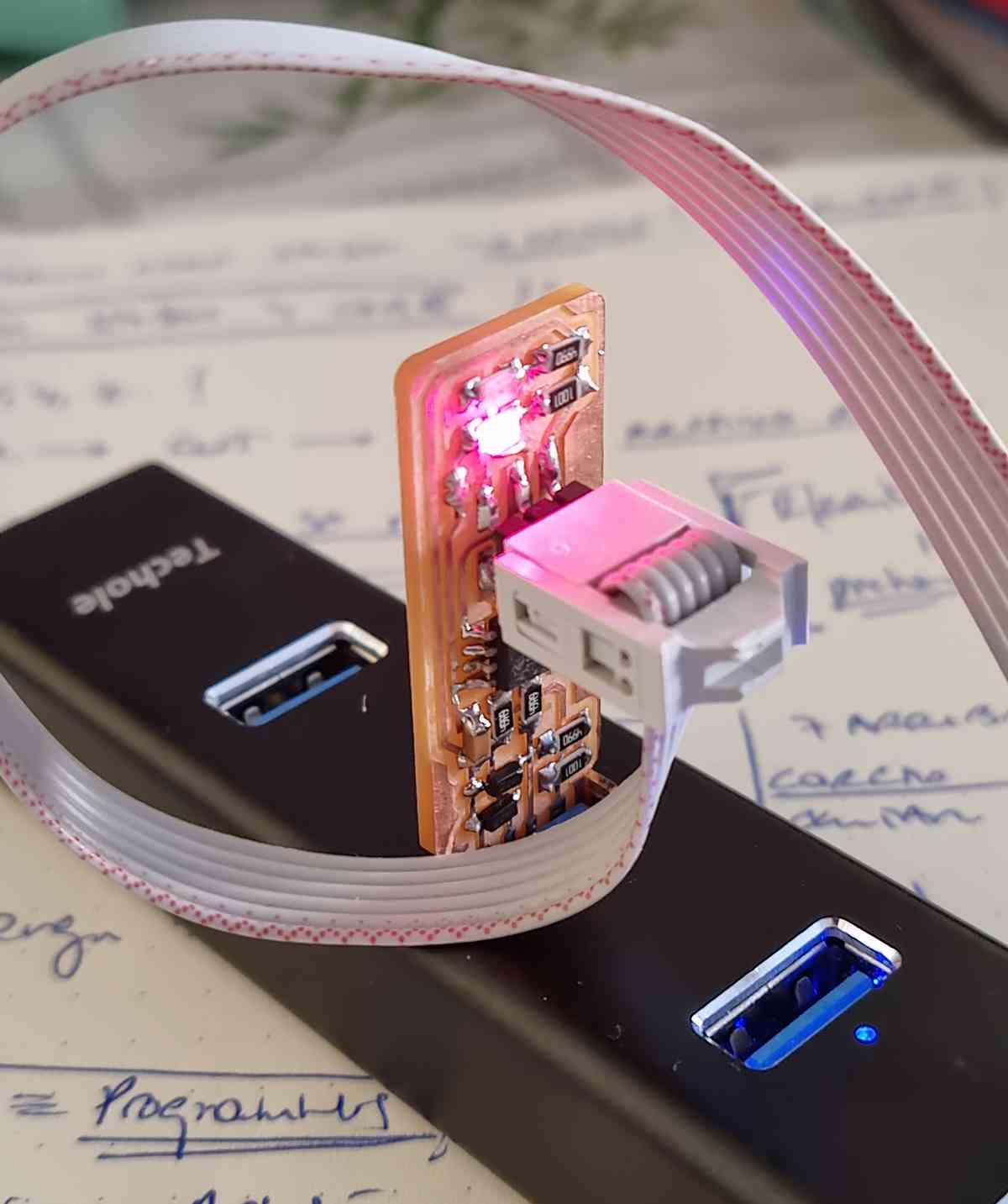 FabISP programmer
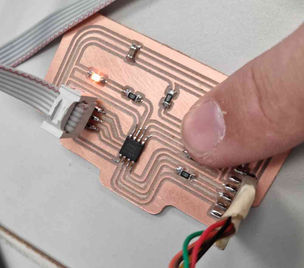
My first board.
In order to program my board, I used Arduino IDE, an open source software to write and upload code to different types of boards, including non-arduino as ours. In my case, I already had it installed (week06 assignment) with the adecuate libraries for our board (ATtinyCore). With all the settings arranged I only had to write a new code in our program. This week is one of the few weeks were I have a little experience. In my case, I learnt some coding with Arduino Blocks, explained later on in the grupal assignment.
My goal for this first spiral is to code my board with different programs, so in order to achieve it, I did as follows:
| Open Arduino IDE and make sure that you´ve got the needed libraries installed. In our case an ATtinyCore library. |
| Go to TOOLS and check your microcontroller settings: Board, Chip, Clock, PORT, programmer. I already had it prepared from the electronics design assignment. |
| Open a NEW SKETCH: In my case I opened the sketch I used for the hello-world and modified it. |
| Edit your SKETCH: My first sketch made the led BLINK sveral times with time delay using: digitalWrite (pin number, HIGH/LOW) and delay (time to delay) commands. |
| Once the sketch is ready: You can VERIFY/COMPILE your sketch first to check that everything is correct. |
| In SKETCH -> UPLOAD USING PROGRAMMER. |
| After I made a second sketch that changes the led light intensity using: analogWrite (pin number. value from 0-255) and time delay as before. |
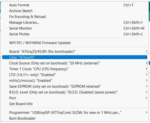 Check microcontroller settings.
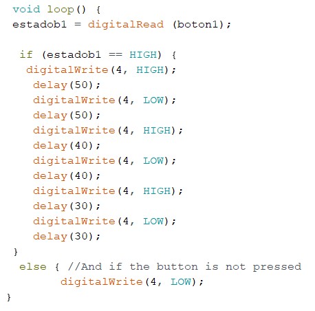 Led blink sketch.
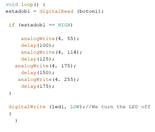 Led intensity sketch.
Download the arduino files created: ledbblink or ledintensity
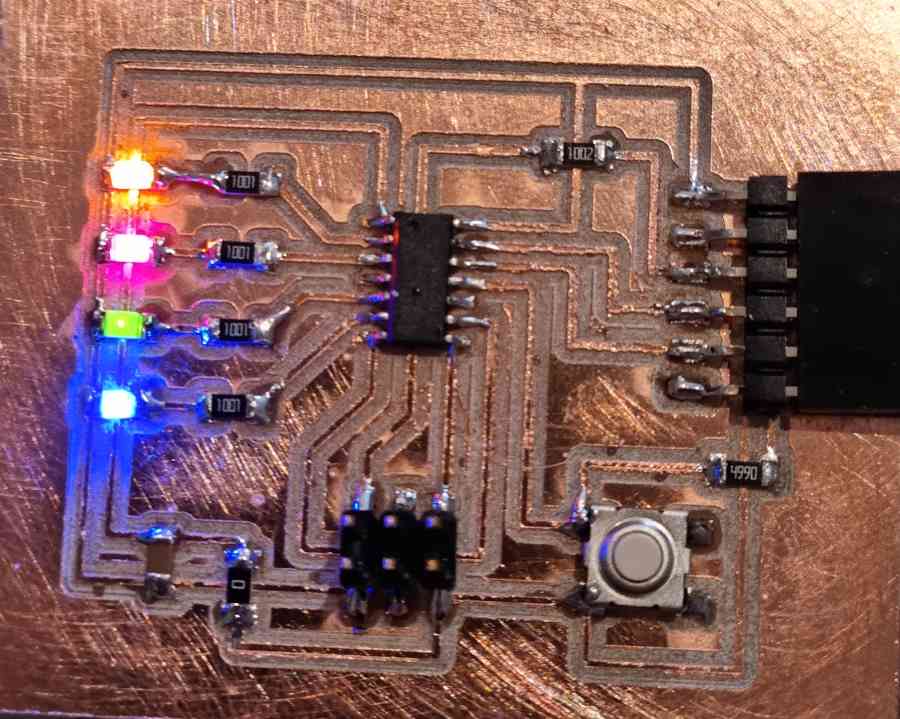
After some entertaining trial-error tests I managed to progam my board to ,with a first sketch, blink changing the delay time and ,in a second sketch, change the led intensity. So, happy with this first results and looking foward for my next spiral.
2. BROWSE THE DATA SHEET OF MY MICROCONTROLLER
The microcontroller that i´m going to use for my second spiral is going to be a ATtiny 44. That will give us more possibilites that the ATtiny45 used in the board programmed before. The main features of this low-power 8-bit microcontroller are:
MAIN FEATURES
- 2K/4K/8K Bytes of In-System, Self-programmable Flash Program Memory.
- 128/256/512 Bytes of In-System Programmable EEPROM.
- 128/256/512 Bytes of Internal SRAM.
- 12 general purpose I/O and 32 general purpose working registers.
- 8-bit Timer/Counter with two PWM channels and a 16-bit timer/counter with two PWM channels.
- Internal and External Interrupts.
- 8-channel 10-bit ADC.
- 14 pin SOIC package: 14S1 14-lead, 0.150" Wide Body, Plastic Gull Wing Small Outline Package (SOIC).
- 1.8 – 5.5V operating voltage.
- Temperature Range:-40°C to +85°C.
As we can see in the pin out image, it´s got a total of 14 pins, of which I can use 4 "free" digital, and 2 analogic pins to design my board.
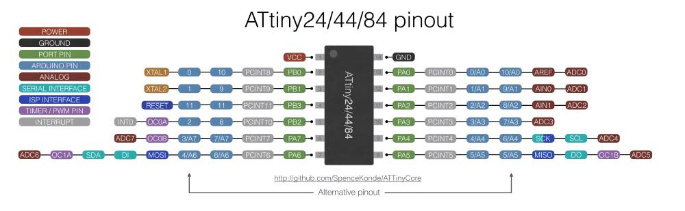 ATtiny 44 pinout.
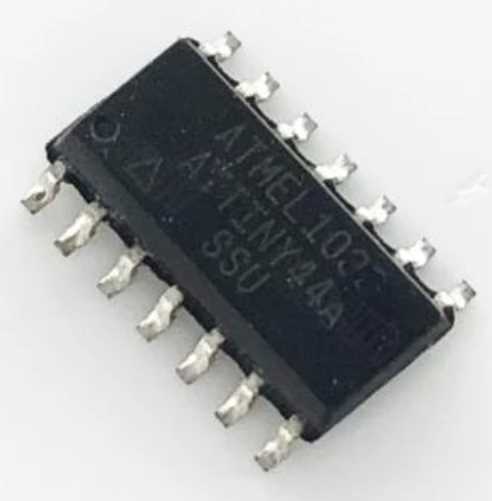
The ATtiny44 that we are using is the 14S1 package with a 14-lead, 0.150" Wide Body, Plastic Gull Wing Small Outline Package (SOIC).
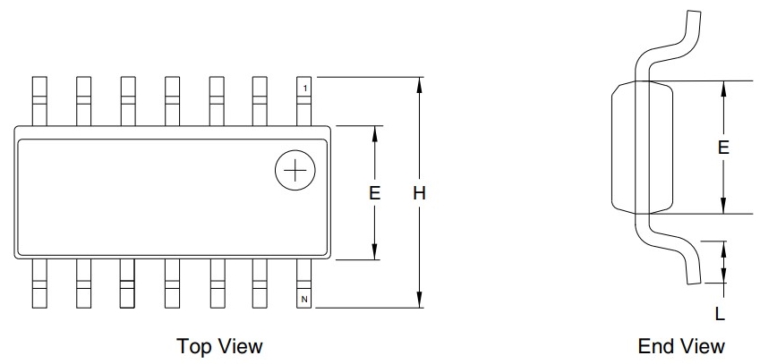 ATtiny 44 packaging.
Here you can check the block diagram of all the instructions that can execute:
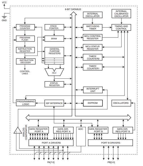 Block diagram.
3. DESIGN, SOLDER AND PROGRAM (TWO VERSIONS) OF A SECOND BOARD
For the second spiral I´m going to use the ATtiny44 microprocessor, browsed before, for two reasons. First, it has more pinouts that the ATtiny45, and I need more outputs for my second board. And second, it uses the same programming proccedure that the ATtiny45, so this will help me to get it done with a learning curve that fits better to my spiral goal. If all goes well, my next spiral would be to use a SMD11C microcontroller, with all that that implies.
My idea for this spiral is to make a board with 4 led output with two different input versions:
- Button version: That will have a tactile button input that will light the leds depending on the arduino coding.
- 4 headed pin version: That will allow me to test different pressure inputs and therefore advance in my final project design.
My idea is to begin to practice my arduino coding programming the Button version to do something, and after, applying that experience in the 4 headed pin version, adding an exchangeable input .
So, I prepared my board DESIGN RULES connections:
| PB0, PB1, PB2 y PA7: Connected to LED + 4xResistor(1001) connected to ground. |
| PA6: Connected to MOSI(Isp)). |
| PA0: Connected to Tx(Ftdi). |
| PA1: Connected to Rx(Ftdi). |
| PA2 for the BUTTON VERSION: Connected to switch button (VCC + 1xResistor(4990) connected to ground). |
| PA2 y PA3 for the 4 HEADED PIN VERSION: Connected to 4x1 headed pin. PA3 also connected to 1xResistor(4990) connected to ground. |
| PA4: Connected to SCK(Isp). |
| PA5: Connected to MISO(Isp). |
| PB3: Connected to RST + 1xResistor(1002) connected to VCC. |
| GND: Connected to all the components. |
| VCC: Connected to all the components. |
I created the schematics first and after the PCB documents using EAGLE, as explained in electronics designs assignment. The components used from the fab library were:
COMPONENTS NEEDED
- Capacitator: CAP_UNPOLARIZEDFAB x1.
- Led: LEDFAB1206 x4.
- Resistors: R1206 x6 (4x1001, 1x1002 and 1x4990).
- 1x4PinHead: PINHD-1X4/90.
- 1xSWITCH: SW_SWITCH_TACTILE_6MMX6MM.
- UC_ATTINY44SSU x1.
- Connectors: 03X2PINHEAD-SMD x1, 06_FTDI_SMD_HEADER x1.
These are the results from each step. I followed the same proccedure as the electronics design week, but this time I was more aware of the trace width, establishing it in 16mm. I have to say that EAGLE gave me a lot of problems regarding schematic and PCB syncronization (not related to libraries and ERC issues). You have to be very careful every time you close and open your work because you have the risk of having to start your PCB design from 0. If these problems persist, I will think of changing to another program such as KiCAD.
Here you can check some images from the 4 PIN INPUT VERSION:
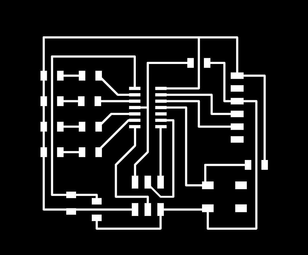
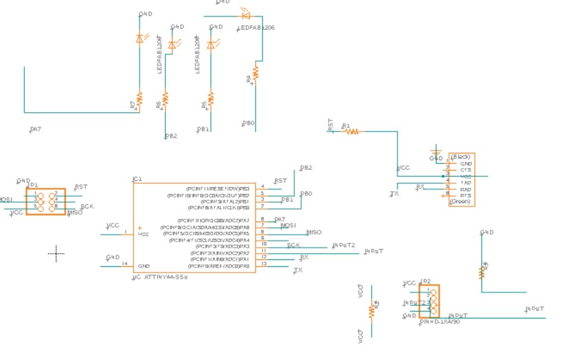 Eagle schematic.
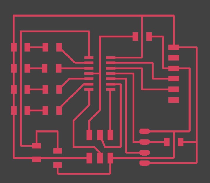 Eagle PCB.
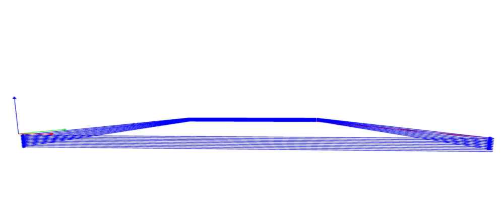
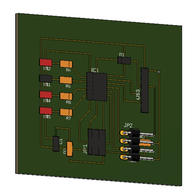 3D simulation.
Once the design was ready, I opened it in ModsCE with the same settings as used in previous weeks. In this case, after checking the TOOL PATH, I had to adjust my design, because the toolpath wasn´t able to separate two lines. I also struggled a bit with the outline design, because for unknown reasons, I kept having weird toolpaths in ModsCE even do nothing seemed to be wrong in the original .png:
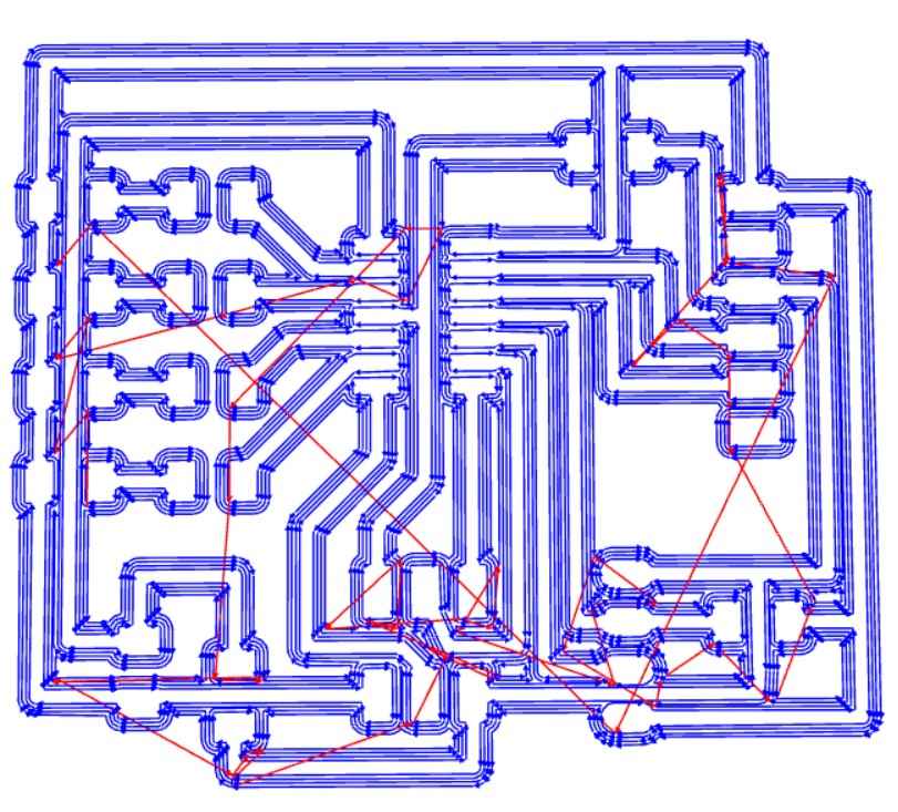 Inline toolpath.
 ModsCE settings.
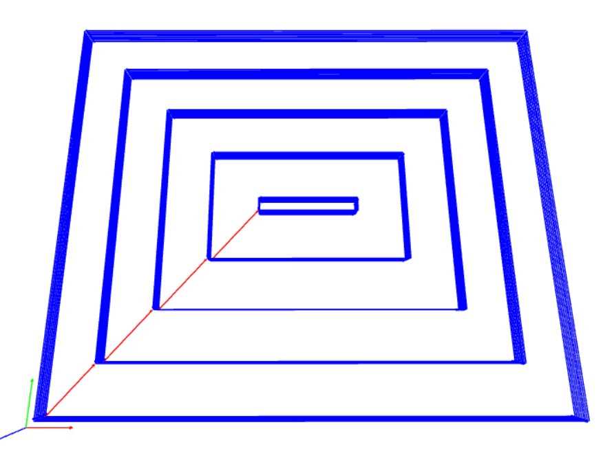 Outline toolpath problems!.
In order to solve the problem with the outline toolpath, I installed and used Gimp, an open source and free GNU Image Manipulation Program, recommended by my fabmate. So, checking closely the .png file, I found at maximum zoom that I had a black trace in the external outline. So, I proceeded to fill in white that black line, inverted colours and exported it again as a .png file (check that the dpi´s don´t change!). And when I opened it again in ModsCE, adjusted settings and viewed the toolpath, this time everything was OK! So, leason learned, double check your .png images thoroughly:
 Black line trace in the outline design.
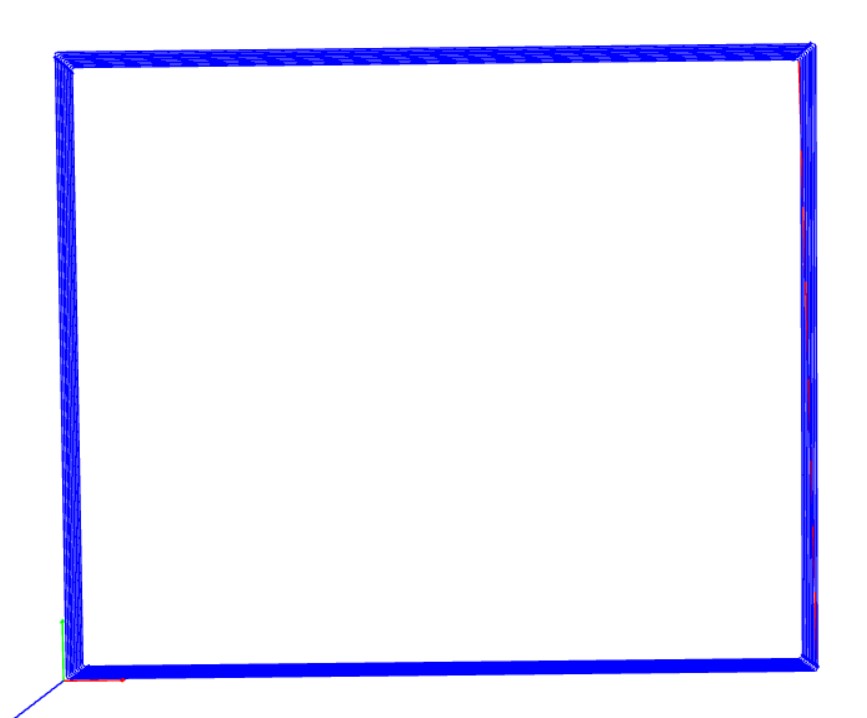
 Correct outline toolpath.
Download eagle files: Eagle schematics or Eagle board for 4 headed input version.
Once I had the designs ready to mill. I used our Roland Modela MDX-40A as in previous assignments, and after having both boards correctly milled with no mayor issues (I know, I can´t believe it either..!) I stuffed the corresponding components detailed above:
Soldering went good, I even enjoyed it, took my time and was capable os solving a removed pad of a resistor during the milling process.
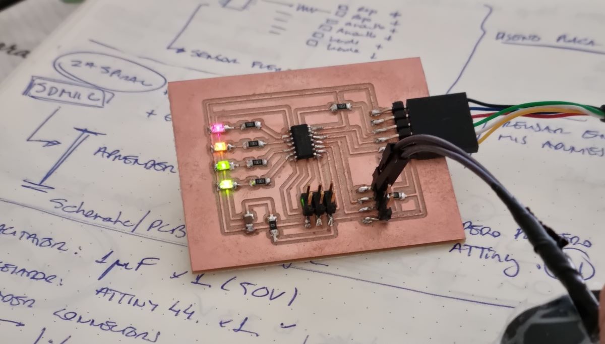
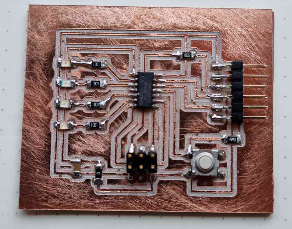 4 leds + button version.
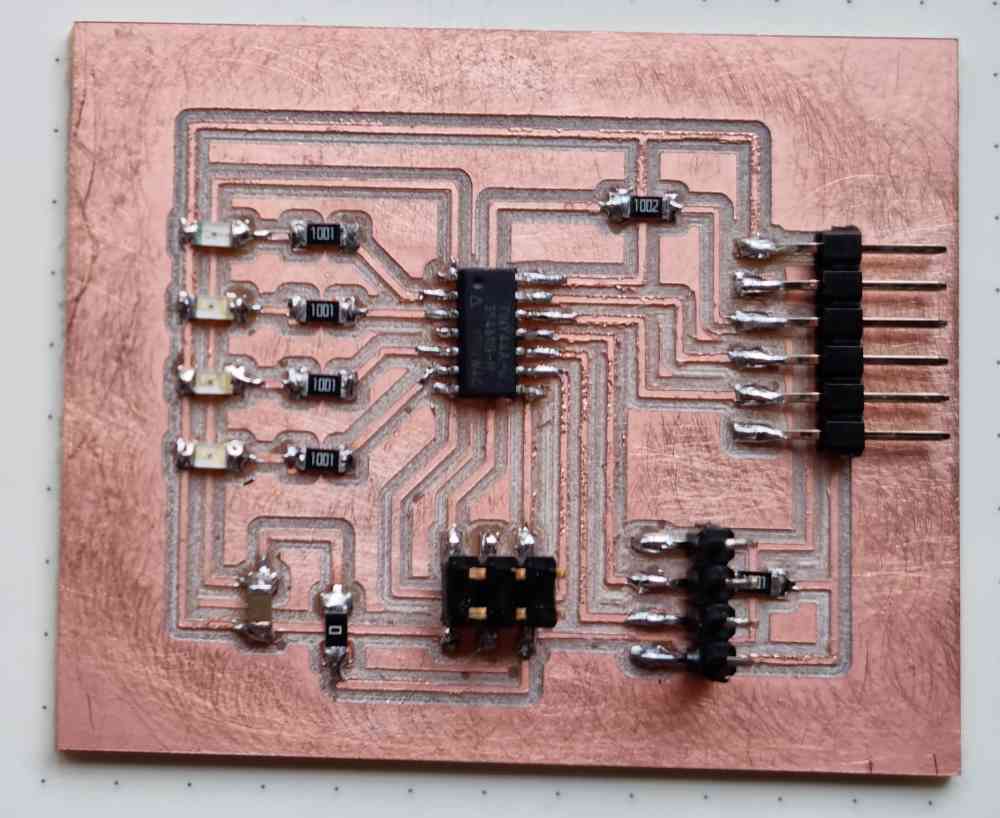
4 leds + 4 pin header version.
PROGRAMING THE BOARDS TO DO SOMETHING
I order to program my boards, I started with the BUTTON VERSION board. I´ve never programmed nothing directly in arduino IDE, so I reviewed some led blinking tutorials and language reference from arduino, that helped me understand the structure and general commands in arduino. So, this is what I did:
| Open new file in Arduino IDE. |
| Define your inputs and outputs: In my case 4 leds and the button: Check the pin out of your microprocessor to know the crrect pin of each output and input device. |
| VOID SETUP We must specify to the microcontroller the commands it will execute at boot time. |
| VOID LOOP: It´s the main function. It where we have to put the commands that will be executed as long as the Arduino board is enabled. The microcontroller will go from the first command to the end and jump immediately to the beginning to repeat the same sequence. And so on an infinite number of times (as long as the board has power supply).. |
| VERIFY/COMPILE: Verify that your program runs properly before uploading it to your board. |
| UPLOAD USING PROGRAMMER: In my case, a specific programmer for the ATtiny44. |
| TEST YOUR BOARD. |
After testing and re-testing different commands, I edited a simple program using if, for and else control structure:
Download the arduino file created: 4ledsbutton .ino
4 HEADED PIN INPUT VERSION BOARD + FINAL PROJECT
I was also interested in doing a second board (4leds output + 4headed pin input) as a test-try exploring spiral for my final project. My idea was to try different inputs to test pressure and correlating its value with leds activation. To start with the tests, I did two things first:
- Create a home made pressure input: With 4 layers of velostat and two cables.
- Test with an arduino board maximum values with different resistors.
With the aim of starting to use my weekly assignments to develop my final project idea and design.
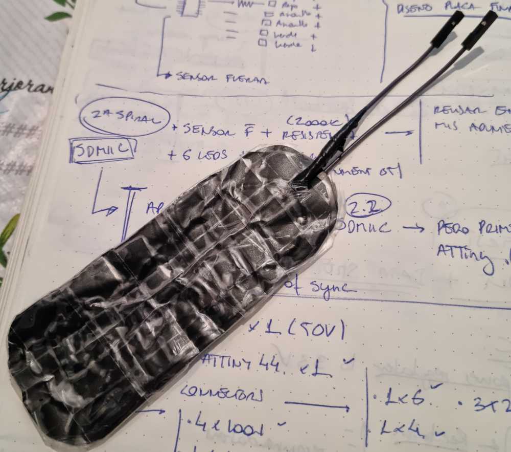 Home made pressure input.
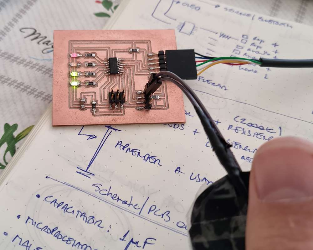 PCB + input.
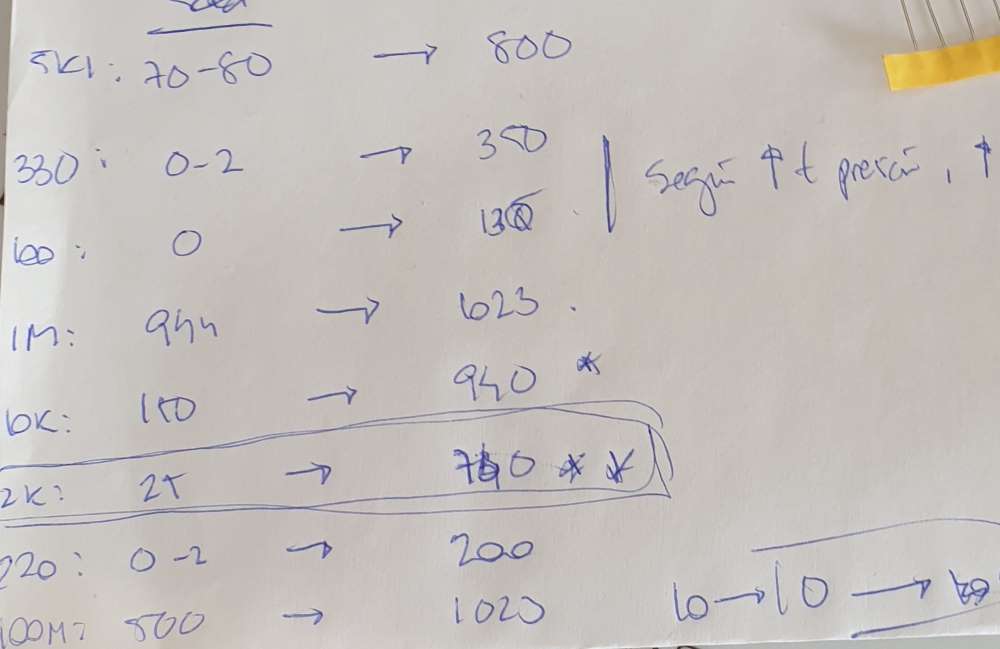 Calculating resistors value.
After the regional review, I found out that I connected wrongly Rx and Tx. To be honest, I didn´t even think I´d use them, so I forgot completely during the design process (I won´t forget again). They recommended me to use software-serial library, which permits you to change pins role in your code. I´ve gave it a try, but still need more practice and time!
Download the arduino file created: pressureleds .ino
For final thoughts on the individual assignment. I´m happy with my learning curve this week, but I still got a lot more to learn. Need to invest time in understanding all the possible parameters that can be programmed, with special attention to output visualization. I know we will have weeks in the future to work on this.
GROUP ASSIGNMENT
1. COMPARE THE PERFORMANCE AND WORKFLOWS OF ARDUINOBLOCKS:
As for the grupal assignment, i´ve got a bit of experience with ArduinoBlocks, a simple and visual arduino based software with a different workflow that, in my experience, helps you to understand basic concepts such as set up, loops, and the possibilites regarding logic, control, fuction options, ect.. that are organized by "blocks" facilitating your first steps in the coding world, mainly in arduino boards.
In order to use it, fisrt you have to create an account. Once created you just open a new project, and start programming. It´s also recommended to download and install ArduinoBlocks Connector, neccessary to connect and program arduino boards
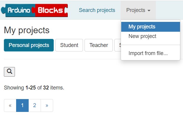 New project,
 Resources.
 Arduinoblocks Connector.
As you can see in the following images, the structure is based in arduino code, with the set up, and loop, but the workflow is easier because the actions are grouped in blocks. For example:
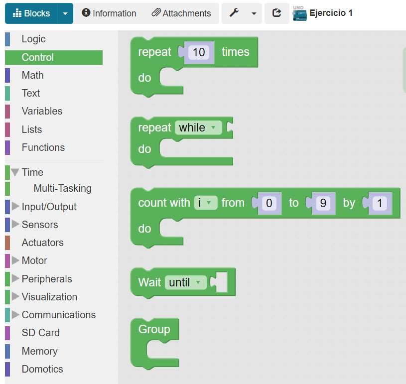 Control blocks,
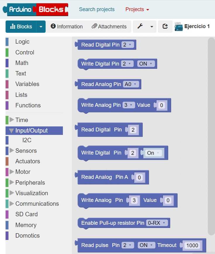 Input/output.
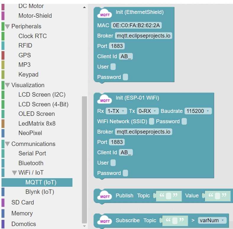 Wifi/IoT.
Once your "blocks" are ready, you just have to connect an usb cable to an arduino board, check the connection port and upload! A good thing about this program is that it also permits you to view your code, and even download it, in Arduino IDE, making it exportable to other programs.
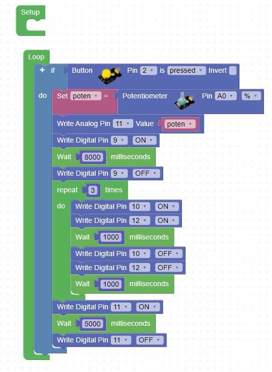 ArduinoBlocks view.
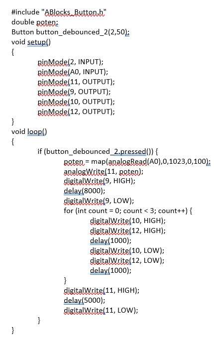 Code view.
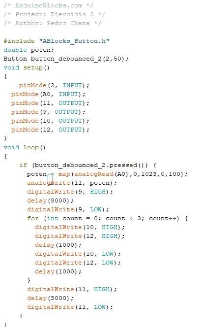 Arduino IDe view.
In my case, i´ve tried to program my board with ArduinoBloks exported Arduino IDE file, but first two things to consider, first, you have to take into account all the libraries used in ArduinoBlocks, because you´re going to need then in ArduinoIDE, second, the size of the sketches are quite big. So, eventually I wasn´t able to uppload it due to the sketch size, its too big for my ATtiny44. So, for final thoughts with ArduinoBlokcs, itS a great program to start coding, and to start understanding and exploring all its possibilites, but its not useful for fab-made programmers. For a begginer as me, is a good way to start with the goal of jumping into other programs in the future. You can check the pros and cons comparison we´ve made below, after exploring the C programming workflow.
2. COMPARE THE PERFORMANCE AND WORKFLOWS WITH C PROGRAMMING:
As this is a group assignment, this workflow comparison is on my fabmate Jon Merino´s group assignment where you can also check the comparison between the different microcontroller used in this assignment. Highlighting the UPDI interface connection of the 1614 MCU and the USB and JTAG interface of the SAMD11. Also the SRAM and CPU difference between the three MCU´s used (ATtiny45, ATtiny1614 and SAMD11). And it was also a surprise that the SAMD11 permits a maximum of 3.63 voltage compared with the 5.5 volts permited by the ATtiny family.
.And finally, in order to add more comparison of the code performance, here you can check the pros and cons that we´ve explored and detected between Arduino IDE, Arduino Blocks and C programming architectures:
| PROS/CONS | ARDUINO IDE | ARDUINO BLOCKS | C PROGRAMMING |
|---|---|---|---|
| PROS | Simple to use, broad range of libraries and codes, Direct sketching from its editor, community-based | ++ Simple, a good way to start coding. Permits saving and project sharing. | Low cost, fast execution and compilation, less memory needed on MCU´s, Portable, easy debugging, low level control on the MCU registers. |
| CONS | Limited processing power and working memory for more complex programming. | Heavier libraries, limited grouped functions in "blocks", not suited for fab academy interests. | + Complex, supports less libraries. Lacks of constructor. |
To wrap it up, it´s been a lot of testing and a lot of learning, but definetely we´ve understood how important is to reach up to the microcontroller´s DATA SHEET before working with it. It´s a mandatory proccedure that will ensure you have no surprises later on. I´m fascinated with this "world" and i´m looking foward to learn and go deeper into it.
Back to top