Week 8: Embedded Programming
Group Assignment: compare the performance and development workflows for other arquitectures
Different MCU's. Comparing ATtiny45, ATtiny1614 and SAMD11C
First of all, let's compare the different features of the three MCU's
| ATtiny45 | Attiny1614 | SAMD11 | |
| CPU | 8-bit AVR | 8-bit AVR | 32-bit ARM |
| Number of Pins | 8 | 14 | 14 |
| Number of I/O pins | 6 | 12 | 12 |
| ISP interface | Yes | Yes | Yes |
| I2C interface | No | Yes | Yes |
| USB interface | No | No | Yes (2.0) |
| UPDI interface | No | Yes | No |
| JTAG Interface | No | No | Yes |
| UART Interface | USI | USART | USART |
| ADC channels | 2 | 3 | 5 |
| Timer Module | 2 | 5 | 4 |
| Analog Comparators | 1 | 3 | 2 |
| DAC Module | 3 | ||
| PWM outputs | 2 | 6 | 7 |
| Internal Oscillator | 0-8MHz Calibrated Internal Oscillator | 16 and 20 MHz | 7 |
| Flash | 4KB | 16KB | 16KB |
| SRAM | 256B | 2KB | 4KB |
| CPU Speed | 1MHz | 10Mhz | 48Mhz |
| Voltage | 2.7-5-5V | 1.8-5.5V | 1.62-3-63V |
First of all, the ATtiny45 is obviously a smaller MCU, with less PINs and input/output capabilities, and also a smaller program memory (4KB). So it's suitable for small and simple tasks that don't require big features.
ATtiny1614 and SAMD11 are more comparable MCU's, with more input/output capabilities and memory (16KB Flash).
Interface and programming
ATTiny45 has limited interface options and it has to be programmed through a programmer via ISP. But speed of uploading software is higher than ATtiny1614 via UPDI.
LED blinking program compiling and uploading:
- Attiny45 7.5 secs
- ATtiny1614 9.5 secs
- SAMD11 4.23 secs
ATTiny1614 can be programmed trough a UPDI interface (single wire) and offers I2C and USART serial communications.
And the USB interface is definitely the strong point of the SAMD11. Once the bootload is loaded, it can be programmed and operate through a USB 2.0 interface. It also can configure different serial interface options.
Compatibility and working with them
Once said that ATtiny45 is a smaller MCU, let's compare ATtiny1614 and SAMD11: In my experience, the 16KB memory of the SAMD11 is a little bit small for a 32 bit processor. Any compiled program reaches easily that volume, and it is common to get an overflow message.
Also it has a lack of compatibility with many of the libraries available. So if you like to program the code yourself on a compact compiled executable it could be a good option, taking into account the availability of the USB port. Otherwise I would recommend to use the 1614 instead.
Different programming workflows
Programming the board directly in C language
In this case, to change the MCU I used an Arduino UNO we had in the lab. Fortunately, we had the AVR toolchain installed from the week 4. I programmed the simple led blinking program.
I had an Arduino UNO with a led connected to pin13.
In C language you must address the ports directly, so you have to figure out the real port number of the pins. Pin 13 is the 5 pin of the B port, port B5 (0B100000).
This is the code in C:
#include <avr/io.h> //It includes the parameters for the specified MCU#define F_CPU 16000000 //CPU clock to 16 Mhz#define BLINK_DELAY_MS 500#include <util/delay.h>int main (void){// Arduino digital pin 13 (pin 5 of PORTB) for outputDDRB |= 0B100000; // PORTB5while(1) {// turn LED onPORTB |= 0B100000; // This operation applied with the mask 0B100000 set only the bit of the pin 5_delay_ms(BLINK_DELAY_MS);// turn LED offPORTB &= ~ 0B100000; // This operation applied over PORTB sets 0 only the bit of the pin5_delay_ms(BLINK_DELAY_MS);}}
Then you have to edit a Makefile to make compiling and deploying easier:
Makefile:
CFLAGS ?= -Os -DF_APU=16000000UL -mmcu=atmega328pLDFLAGS ?= -mmcu=atmega328pall: led.hexled.hex: ledavr-objcopy -O ihex -R .eeprom led led.hexled: led.oavr-gcc $(LDFLAGS) -o $@ $^led.o: led.cavr-gcc $(CFLAGS) -c -o $@ $<deploy: led.hexavrdude -F -V -c arduino -p ATMEGA328p -P COM8 -b 115200 -U flash:w:led.hexclean: FRCrm -f led.elf led.hex led.o ledFRC:
Yo have to change the parameter "-P" of the deploy instruction to specify the port where the board is connected. If you have doubts you can watch it on the Arduino IDE connection port. (COM8 in my case).
After that just running "make" on the bash terminal you compile the code generating a led.hex code.
$ makeAnd you have the response:avr-gcc -Os -DF_APU=16000000UL -mmcu=atmega328p -c -o led.o led.cavr-gcc -mmcu=atmega328p -o led led.oavr-objcopy -O ihex -R .eeprom led led.hex
After that I just typed "make deploy" to upload the .hex file to the board:
$ make deployavrdude -F -V -c arduino -p ATMEGA328p -P COM8 -b 115200 -U flash:w:led.hexavrdude: AVR device initialized and ready to accept instructionsReading | ################################################## | 100% 0.00savrdude: Device signature = 0x1e950favrdude: NOTE: FLASH memory has been specified, an erase cycle will be performedTo disable this feature, specify the -D option.avrdude: erasing chipavrdude: reading input file "led.hex"avrdude: input file led.hex auto detected as Intel Hexavrdude: writing flash (176 bytes):Writing | ################################################## | 100% 0.04savrdude: 176 bytes of flash writtenavrdude done. Thank you.
Programming in ArduinoBlocks.
From low level to very high level programming. This is documented by my fabemate Pedro Chana here.
Individual Assignment: read the data sheet for your microcontroller and use your programmer to program your board to do something:
As the first step, I read the datasheet for the ATtiny45. Main things extracted from the datasheet:
- It's an 8-bit MCU
- However, the ADC is 10-bit (0-1.024 values)
- 4KBytes In-system programmable Flash: suitable for small programs
- Two PWM channels
- 8-bit high-speed counter
- low-power idle
- Internal oscilator
- Six programmable input/output
- Operating Voltage 2.7-55V
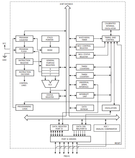
It's also interesting to see the block diagram to understand how it works, the meaning of input-outputs and which registers are. I can see how the portB could be configured so the pins can be analog input (connection with ADC), digital input/output (data register), serial communication (connection with Universal Serial Interface), PWM (connection with oscillators) and the Pin Reset, which goes to the Timing and control unit.
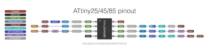
After that I got the pinout.
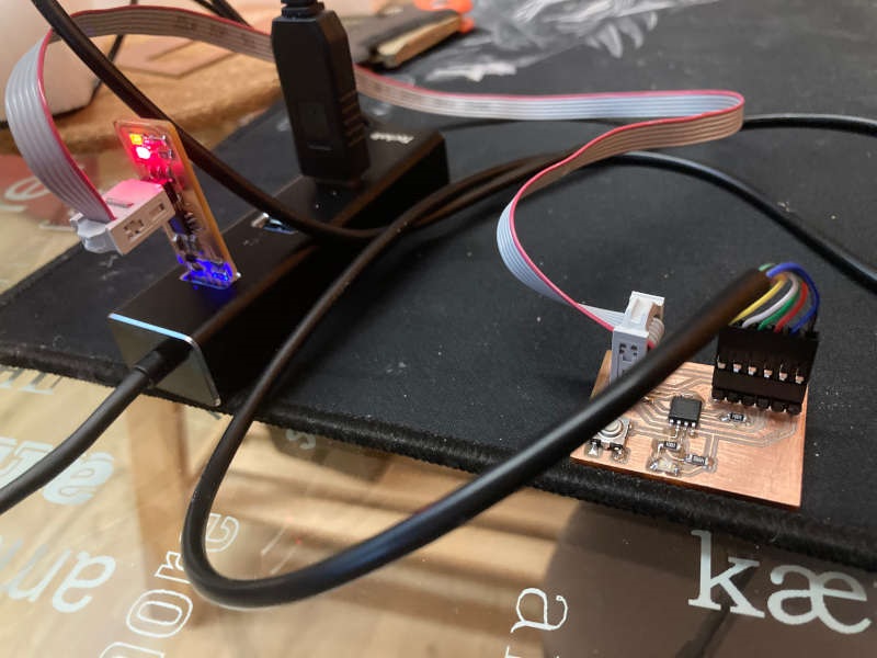
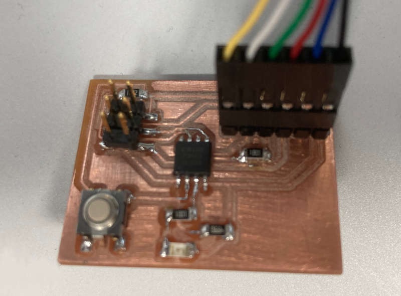
I connected the programmer I made in the electronics production assignment with the board made in the electronics design week:

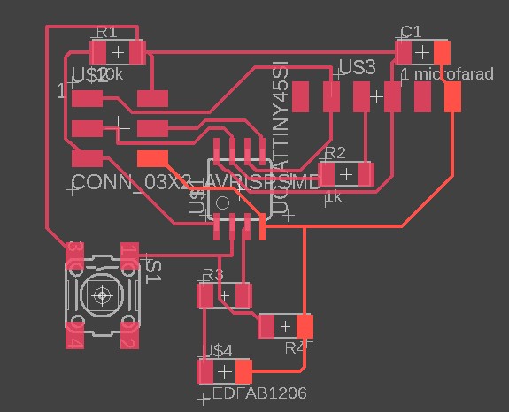
Here is the file of Fusion360 electronics (Eagle)
You can download the file here.
After that I opened the Arduino IDE and wrote a program to blink the led, increasing the number of blinks when you push the button:
//LittleJon led blinkingint led1 = 4; //pinout of the attiny45 of my hello boardint button1 = 3; //pinout of the attiny45 of my hello boardint i=0;int delay1=10;int state1=LOW;int counter=1;// the setup function runs once when you press reset or power the boardvoid setup(){//Stablishing the output and the inputpinMode(led1, OUTPUT);pinMode(button1, INPUT);}// the loop function runs over and over again forevervoid loop(){//reading the state of the buttonstate1 = digitalRead (button1);if (state1 == HIGH){//blinking the led as many times as the counterfor(i=0;i<counter;i++){digitalWrite (led1, HIGH);delay (delay1);digitalWrite (led1, LOW);delay (delay1);}//Increasing the countercounter++;}else{digitalWrite (led1, LOW);//We turn the LED off}}
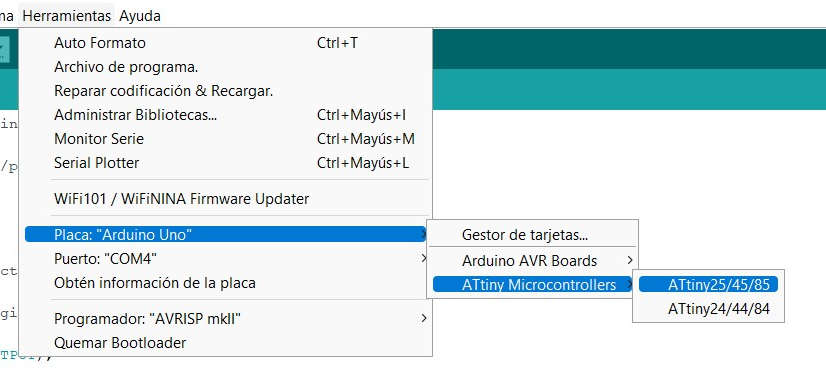
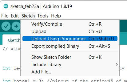
I set the board ATtiny45 on the Arduino IDE settings and sent the program using the option "Upload using programmer".
The programming went well and the program works:
And the adventure begins...the SAMD11
They say we learn a lot from mistakes. If that's true I've learnt a lot this week.
After programming the board with the ATTiny I wanted to explore the SAM family. We have some SAMD11 microcontrollers at the lab, so I thought it would be a good idea to try something with it.
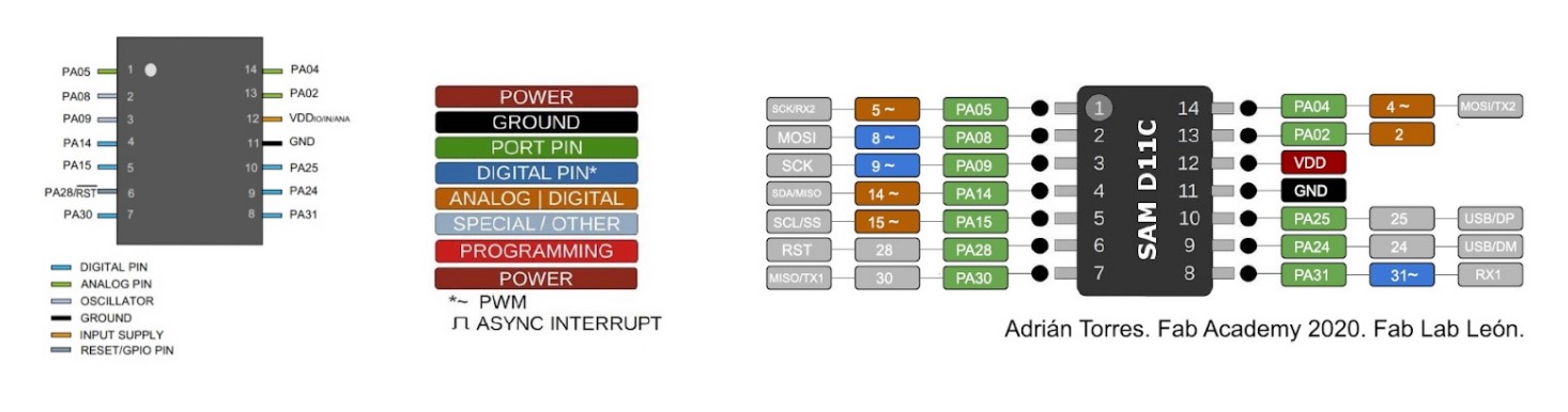
This is the pinout for the SAMD11:
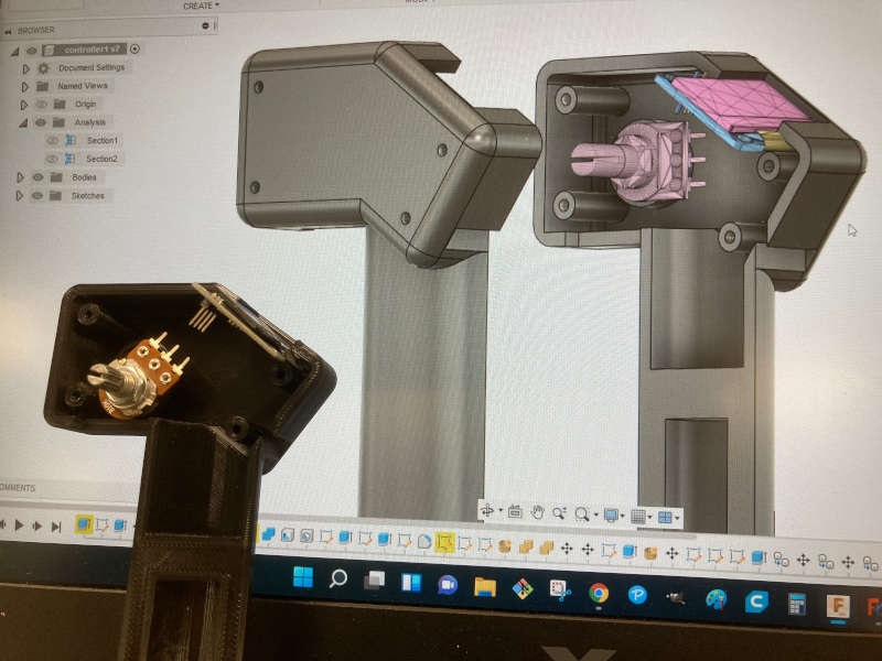
My plan was to do the game for 4 players, so I will need 4 inputs for the push buttons and 2 or 4 outputs for the LED strips.
I also saw the SAMD11 general purpose board made by Quentin Bolsee. I thought it would be a good idea to replicate it and use it for my small project.
So I got the .png files and uploaded them to modsproject. I launched them to the Roland Modela CNC machine and got the first version of the board:
As you can see, the edges are very rough, and some parts are undercut. It was friday, and I've just received a Genmitsu 3018 ProVer at home, so I decided to make it with the Genmitsu.
I spent many hours and had any kind of issues with the machine. I'll mention here the main things to take into account when you use it to make PCB. I followed the repository of Luis Díaz-Faes, who used the machine before me. Thank you, Luis, without you it would be even worse...
So I used the Easel program. It's recommended by SainSmart and Luis is also using it.
1-Be careful with the Z probe calibration. Specially if you use V-shape mills, the calibration of the Z-axis is of course critical. And the probe thickness for this machine by default (14.99 mm) is not the real one (14mm in my case). I changed it but for some reason it wasn't saved, so in my first attempt I milled almost a mm below the right one. Disaster.
2-In my experience, the Easel program for Windows has some very critical errors. It's suposed that when you press the stop button, the Z goes up. Well, sometimes the Z goes down instead of going up. Regardless you are fast hitting the emergency button, probably the tip of the mill is going to break against the material..Now I press the pause button, disconnect the machine from the computer and move it manually.
Note: I broke 3 mills due to this bug.
3-Review if the tip of the mill is really sharp. One of mine wasn't (because of the problem I mention above). I spent a lot of time trying to calibrate the deph correctly, and the problem was that the mill wasn't sharp enough and the trace was wider than needed...
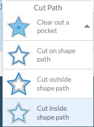
4-Cut path: due to the type of .png files that Eagle generates, if you choose "Clear out a pocket" the amount of material you have to mill is huge. So you have to choose outside or inside the path, and the traces are usually thinner because of that.
Disaster collection:
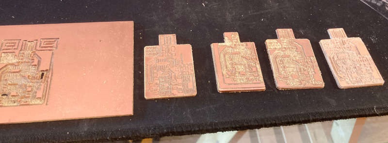
After lots of trials I got a decent one, setting the cut path "outside the path" and a cut deph of 0.2 mm, with the V-shape mill.
It wasn't my best day. And when I soldered the SAMD11 I put it on the wrong side. So I had to desolder it. And in the process of putting and taking it some tracks broke. Besides that, I didn't have the right connectors for this board. I tried to adapt the ones I had, but it was harder than I thought.
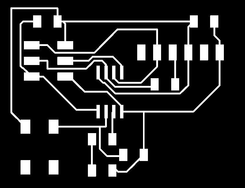
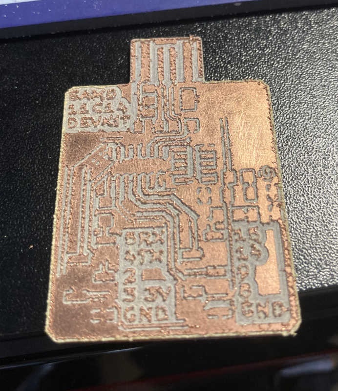
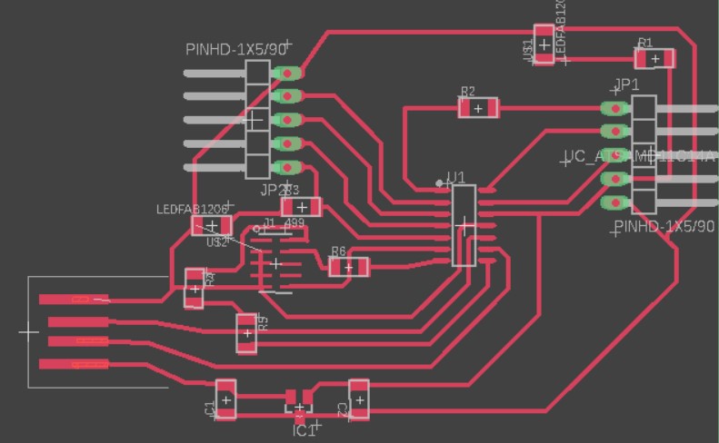
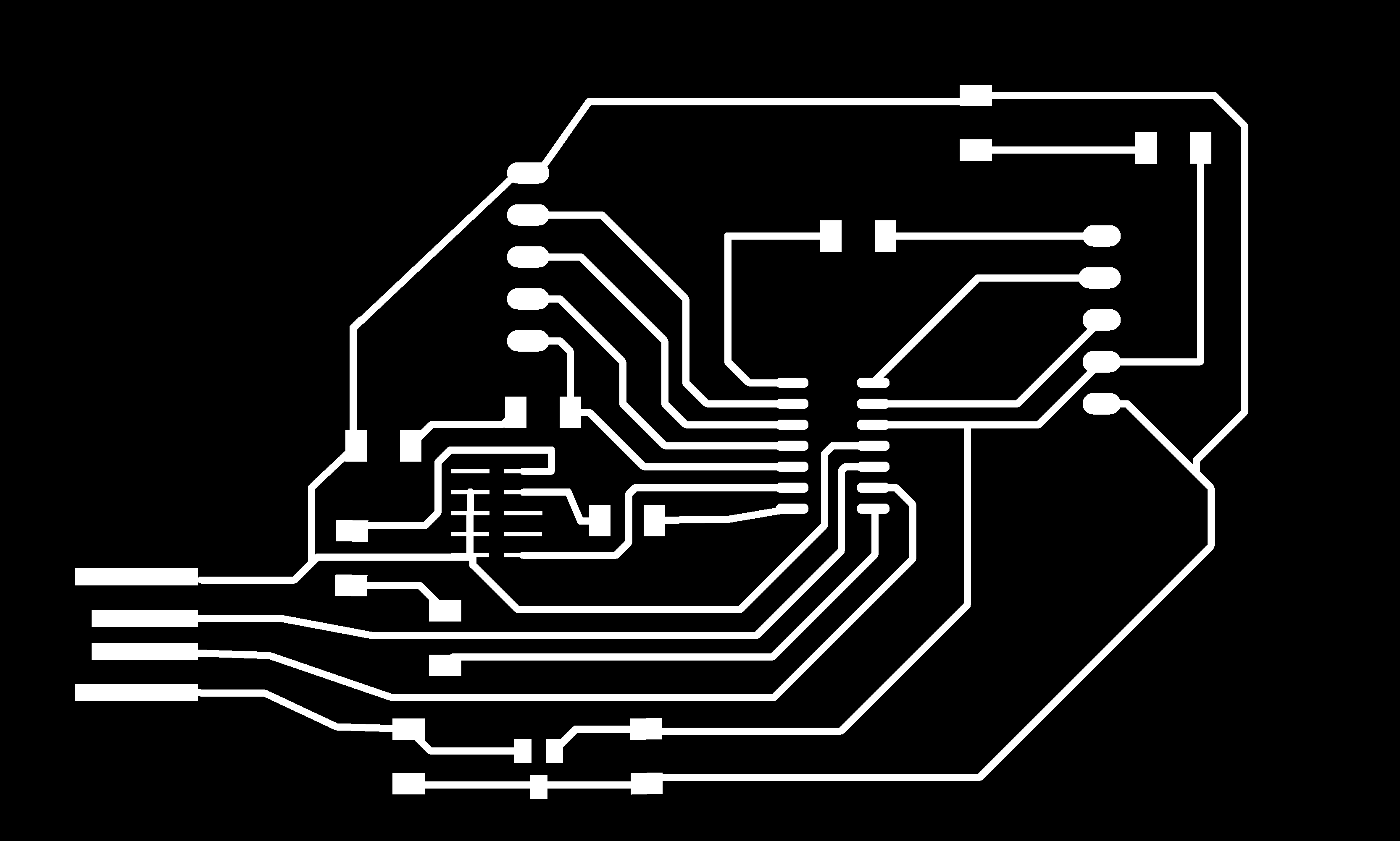
So, on monday, at the lab, I decided to make my own SAMD11 general purpose board, adapting the Quentin Bolsee's, using the pieces and components values we have at the lab and making it wider and more spacious. The "Jonino".
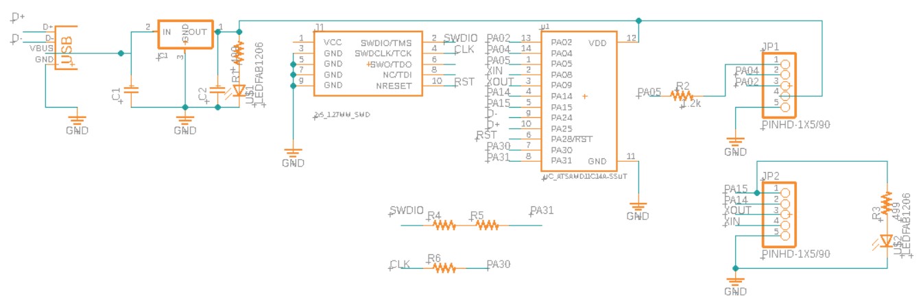
Eagle file is here.
After designing it on Fusion 360 Electronics (Eagle) I used the Roland Modela. But we had some issues with the correct balance of the board. Some parts were undercut and others were overcut.
At the end of the afternoon the mill broke, so I went back home and the Genmitsu machine.
The Genmitsu needs .svg files, so I used Inkscape to convert them from .png to .svg. But when I uploaded the files to Easel I could only use the "Clear out a pocket" on the Cut Path options. If I tried other options there was an error message:

I tried to arrange them on Inkscape, but there were lots of paths, and nothing clearly broken or open. The only solution I found was to use the bucket fill on the black side of the image, so it creates a shape (inverted shape of the traces). I kept this new shape, deleting the rest. And this time Easel took it..
I cut with the "inside cut path" option, but the tracks were too narrow, some of the disappeared. I tried different depths and options, but it was useless.
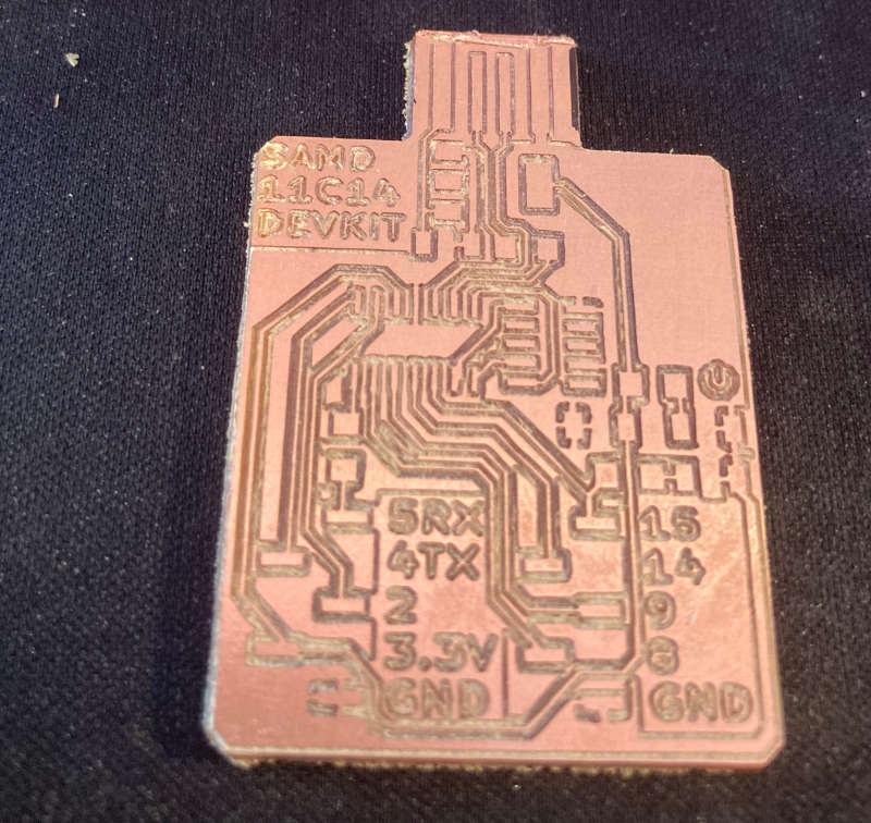
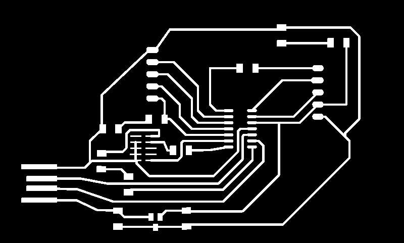
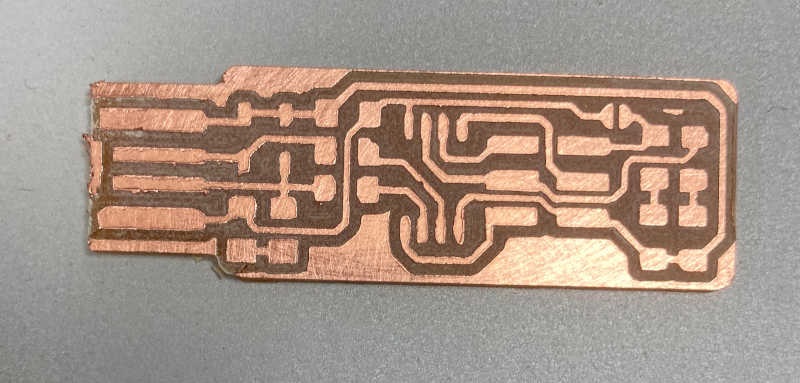
Finally I had the idea of "cheating" the machine telling the mill was a flat one of 0.6mm, so it takes into account the offset of the mill and make the traces wider. Finally I got a good SAMD11 general purpose board:
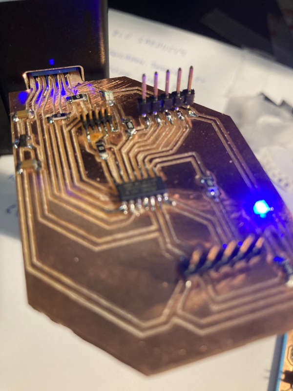
I tried to program it with the new Atmel ICE we've just received in the lab, just to test it. When I uploaded the bootload it showed an error message of invalid response error. I carefully checked the design, the continuity of the traces, the voltage levels, etc.. but the error was still there. After a intensive searching and reading the data sheet, I found out that the Atmel ICE expects to have a high level voltage on the VCC pin of the JTAG connector. So I just temporarily connected the VCC pin of the USB to the VCC pin of the JTAG, just enough to upload the bootload file. And voila!
C:\Users\jonme\downloads> edbg-windows-r32.exe -ebpv -t samd11 -f sam_ba_Generic_D11C14A_SAMD11C14A.binDebugger: ATMEL Atmel-ICE CMSIS-DAP J42700054638 1.0 (SJ)Clock frequency: 16.0 MHzTarget: SAM D11C14A (Rev B)Erasing... done.Programming.... done.Verification.... done.
After that you can program it through the USB port, so the VCC pin of the JTAG is no more needed. I will use this generic SAMD11 board in the following weeks.
