Week 5: 3D scanning and printing

Group assignment
3D printing machine preparation: Creality Ender-5 pro
For this group assignment, my fabmate Pedro Chana and I have to characterize the design rules for the 3D printers and scanner used and available. We are going to use the the Creality Ender-5 Pro , the Creality LD-002R UV Resin LCD, and the Sense 3D Scanner.
Here it is the group assignment documentation. I have to thank Pedro again for his methodical and detailed documentation, putting everything we did together and explaining it in an excellent way.
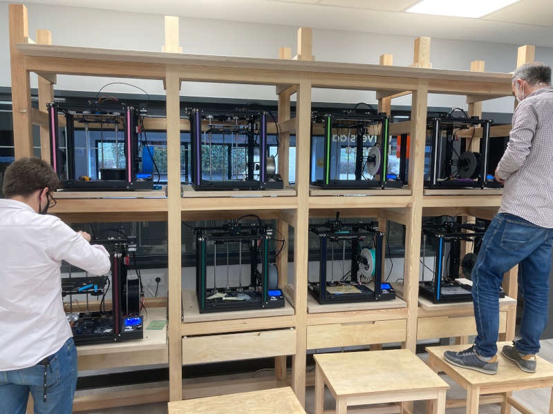
Another acknowledgment: We are very lucky because we have 8 3D printers almost at our complete disposal. Thank to the Universidad Europea and our instructor, Alberto González, to make it possible.
At home I have an Artillery Genius 3D printer, so in addition to the group assignment I'm going to compare the experience and capabilities of both printers.
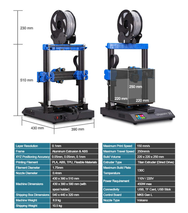
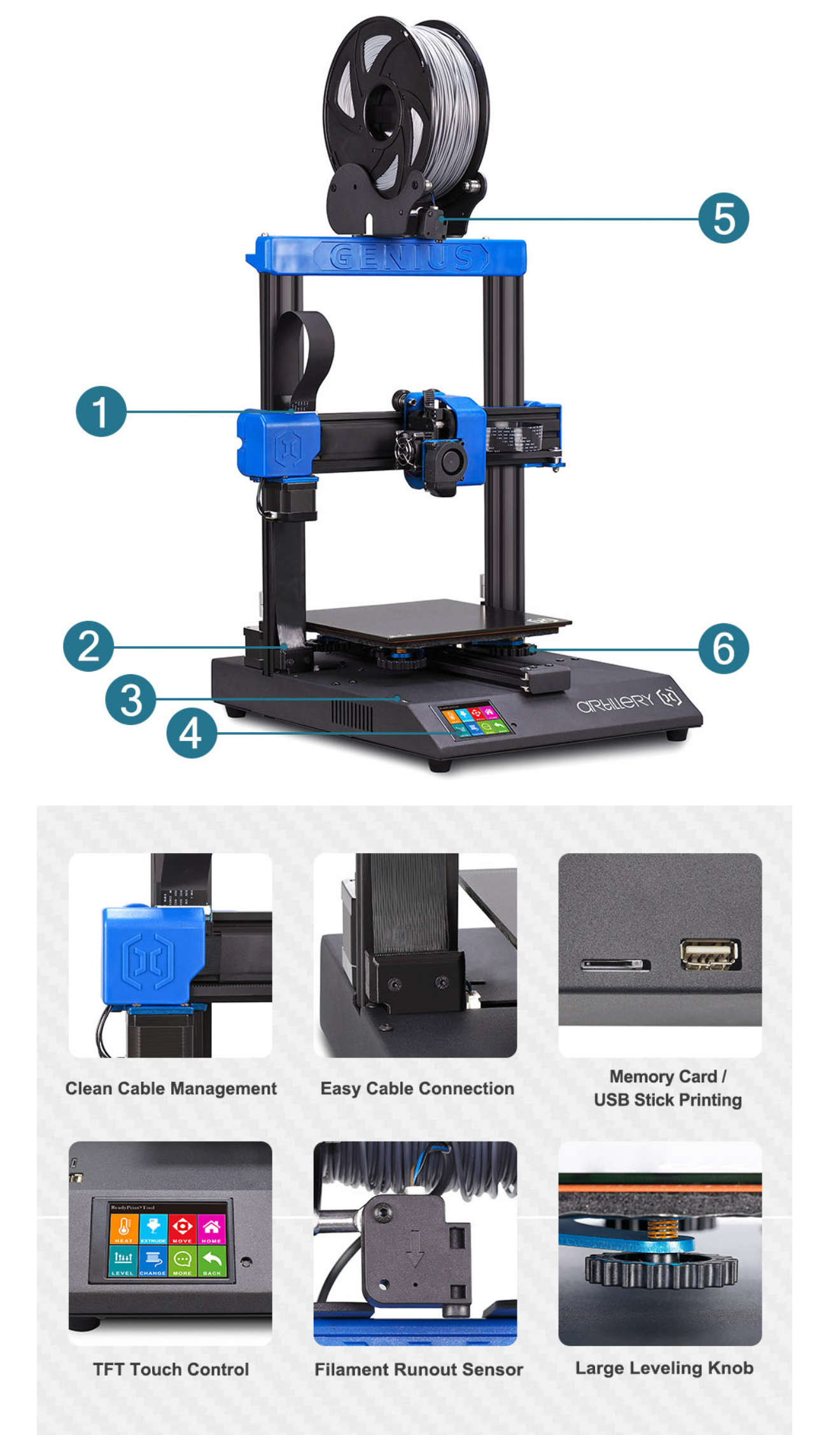
I have to say that I think the Creality Ender 5 Pro and the Artillery Genius are two of the best "affordable price" printers. However, they are quite different: The Ender 5 has a Bowden extrusor and the Genius has a Direct Drive extrusor. The Ender has a movable bed (Z axis) and in the case of the Genius the bed is fixed.
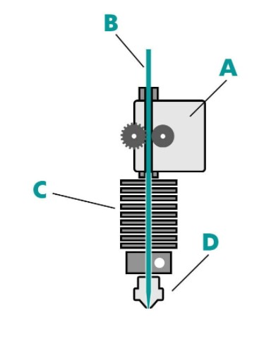
Direct Drive
A. Extrusor
B. Filament
C. Hot-End
D. Noozle
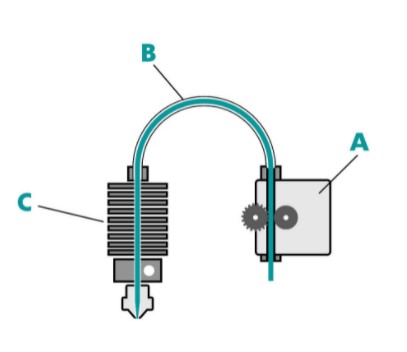
Bowden Extrusor
A. Extrusor
B. Filament inside the Bowden tube
C. Hot-End
Both are good system. In case of the Bowden, the weight of the movable part is lower, so it needs less power to move and the inertia is lower too. On the other hand, Direct Drive is better to control the retraction and to use flexible materials.
In our case, we had some problems at the lab with some filament cloggings inside the Bowden tube. But i have to say that the printers at the lab are 24h printing and a lot of people use them. At home is easier to properly care the printer.
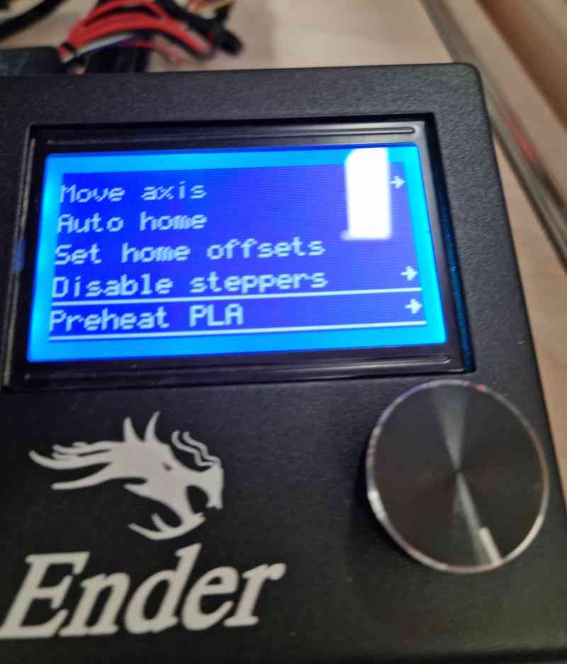
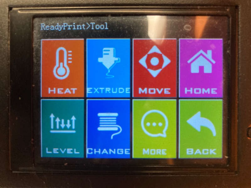
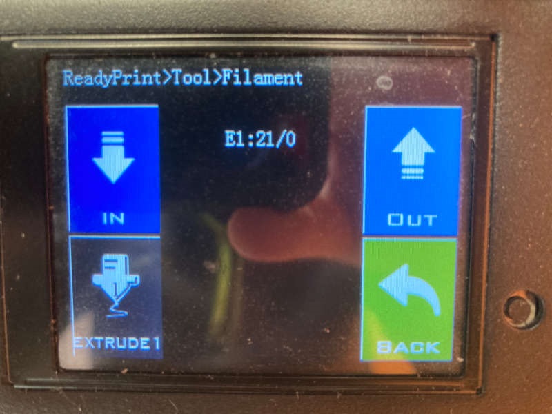
The menu
My impression is that the menu of the Ender is a "low level" menu, and the Genius is more user-friendly. So, perhaps a techie person feels more comfortable with the Ender because you feel you have more control of everything is happening. On the other hand, the Genius menu is very easy and clean. For example, to change the filament in the Ender you have to preheat the hot end, wait until the hot end heats up to the required temperature, manually extrude a small portion of the filament and push down the coupling to release the filament. On the Genius, you just have to push "change filament" and "in" or "out", and the printer heats up automatically and it bips when ready.
Individual assignment
Design and print a 3D object
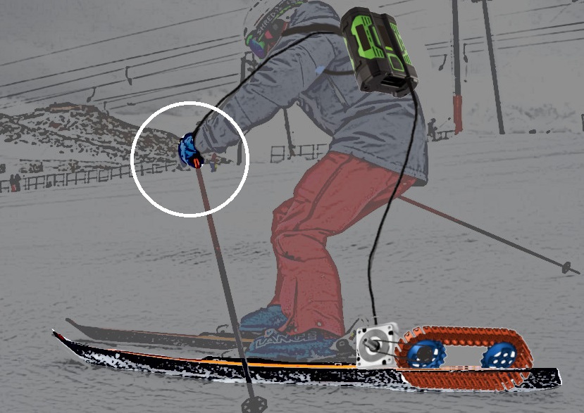
As my final project (an electric ski) is quite challenging, I try to apply the weekly assignments to it as much as I can. So this week I want to make the controller (throttle and battery into) with 3D printing.
I started modelling the controller handle. It has two functions: to manage the throttle and to show the speed and battery level. So it has a potentiometer and a display. I begin with some components I saw in the lab: the Nokia 5110 display and an standard potentiometer.
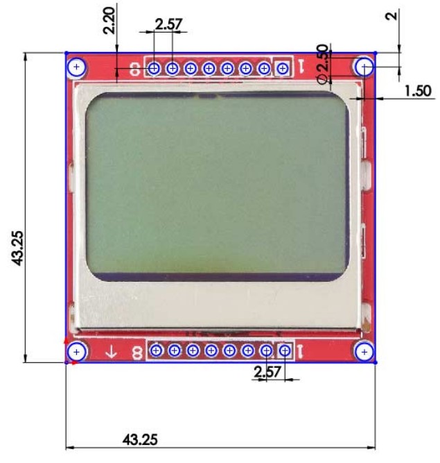
The Nokia 5110 display
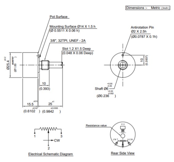
A standard potentiometer
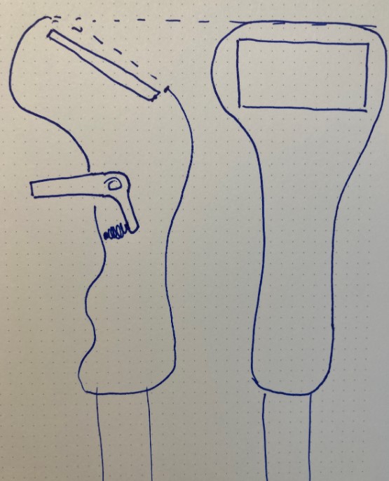
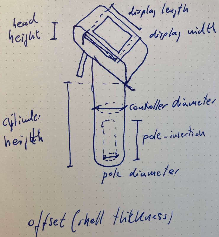
So I sketched a controller:
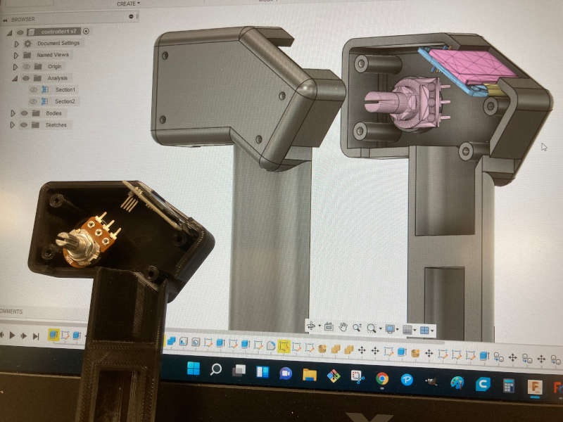
I began to model a parametric design of the controller on Fusion360. I downloaded the model of the 5110 display from Sparkfun, to place it on my design and adjust it.
After this first design of the controller, I spoke with my instructor, Alberto, and he recommended me to use the AZDelivery OLED display, because it's easier to program. Fortunatelly, my design is parametric, so I just had to adjust the size of the display to adapt it.
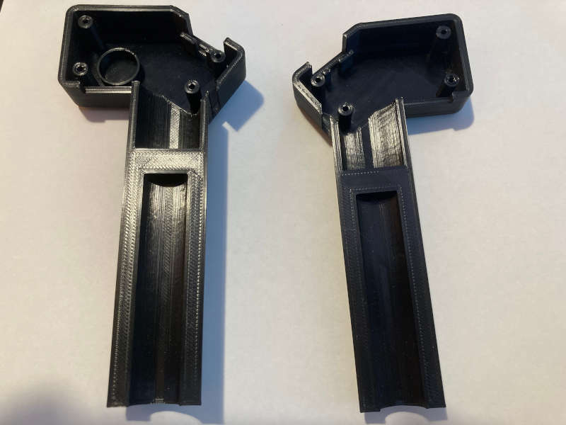
I printed the pieces at home, in my Artillery Genius 3D printer, just leveling the bed and using the parameters I already knew: 220º for black PLA, support only for more than 70º angle, 15% support infill and 20% piece infill. The quality of the result was very good:
And the beautiful magic of it: To think something in your mind, to model it digitally, and to materialize it into a real think... I like it so much.
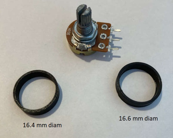
I needed to do some adjustments of the potentiometer and display holders. So, instead of printing the hole piece again, I made only the ring that holds the potentiometer with different diameters. And I found the 16.6 mm ring fitted well.
CAD files of the controller: Controller
Stl files of the controller: Controller_left Controller_right
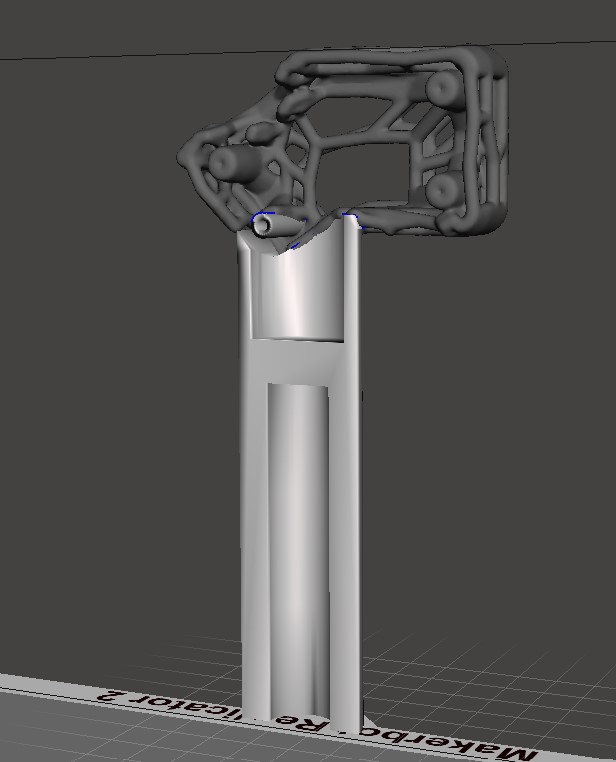
Adding a pattern
I'm not sure if the piece can be done with subtraction techniques (maybe molding?), so I added a pattern to it, using Meshmixer software:
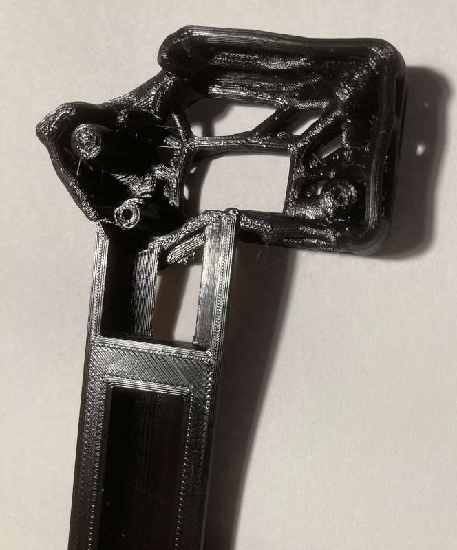
And I finally printed it:
Programming GCode
I've never programmed directly the .gcode files, so I thought it would be a good idea to try it. I wanted to do something that draws lines across different Z positions, to break the usual layer 3D printing.
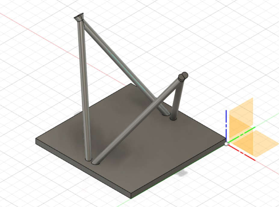
I planned to make a hyperbolic paraboloid (hypar). It's a beautiful shape and it can be built with straight lines. My plan was to make the basic structure of 4 "poles" with the usual 3D design tool and slice it with Cura. And complete the .gcode file with my programming of the lines of the hypar.
So, the first thing was to model the structure with Fusion360. Using the mirror function of Fusion360 is quite easy to make a symmetrical figure:
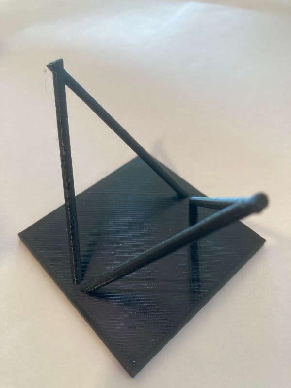
I printed the structure just to check that everything was ok:
After that I wanted to pick the points over the surface of the "poles" to trace the lines. I thought that was easier on FreeCad, because FreeCad always shows the coordinates of the cursor over a surface.
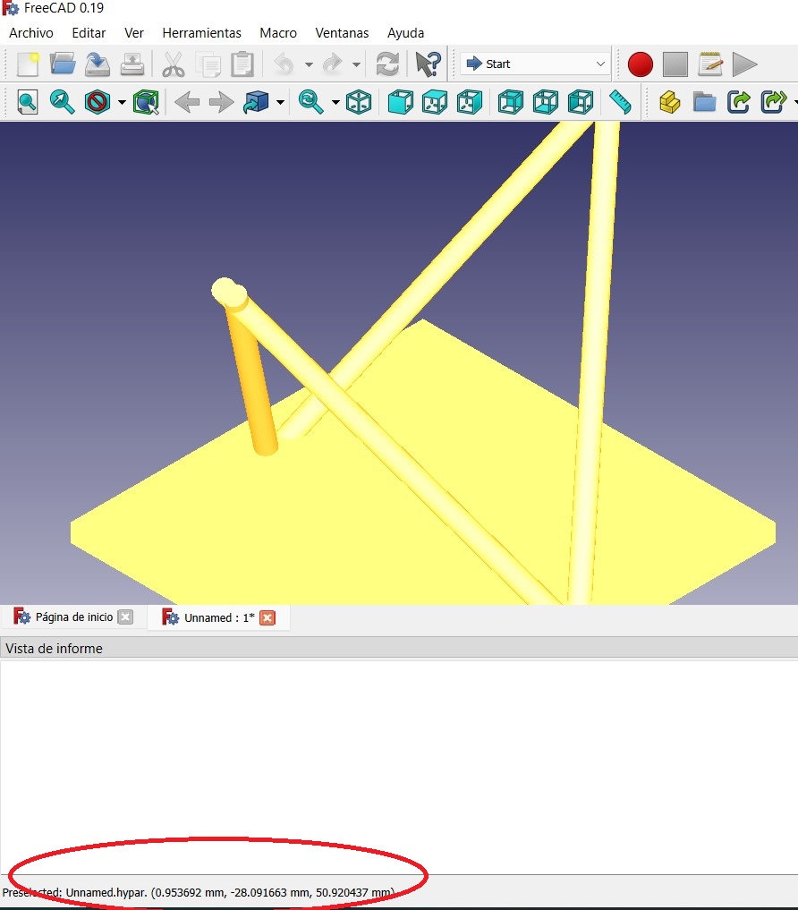
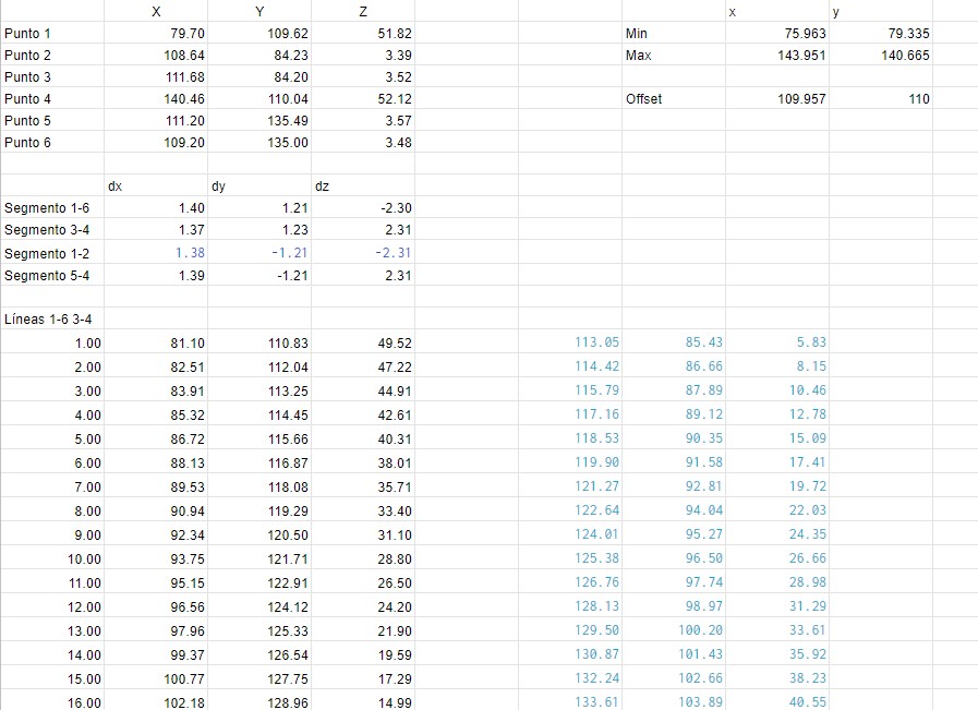
So I picked the points of the corners and interpolated them on a spreadsheet to get all the points along the poles.
However, I realized I had made a mistake: If I try to print that on my 3D printer, the extrusor and the machinery around the noozle are going to hit with the poles structure. So, I decided to do it "virtually": to program the gcode and watch it on a gcode visualizer. Gcode is quite easy and I only had to program some instructions to move the noozle without extrusion (G0) and with extrusion (G1). I also had to understood that the filament is treated "as a forth dimension", and the E parameter of the G1 function represents the length of the filament that has been extruded.
I also realized I had to adjust the offset of X and Y, because Cura places the piece in the middle of the bed (110,110).
So, taking all of that to account, here is my gcode:
;Hypar Jon beginsG0 F9000 X81.10 Y110.83 Z49.52G1 X113.05 Y85.43 Z5.83 E3711.87619G0 F9000 X114.42 Y86.66 Z8.15G1 X82.51 Y112.04 Z47.22 E3711.89619G0 F9000 X83.91 Y113.25 Z44.91 G1 X115.79 Y87.89 Z10.46 E3711.91619G0 F9000 X117.16 Y89.12 Z12.78G1 X85.32 Y114.45 Z42.61 E3711.93619G0 F9000 X86.72 Y115.66 Z40.31G1 X118.53 Y90.35 Z15.09 E3711.95619G0 F9000 X119.90 Y91.58 Z17.41G1 X88.13 Y116.87 Z38.01 E3711.97619G0 F9000 X89.53 Y118.08 Z35.71G1 X121.27 Y92.81 Z19.72 E3711.99619.........
Then I opened the gcode file with the Cura gcode visualizer (preview):
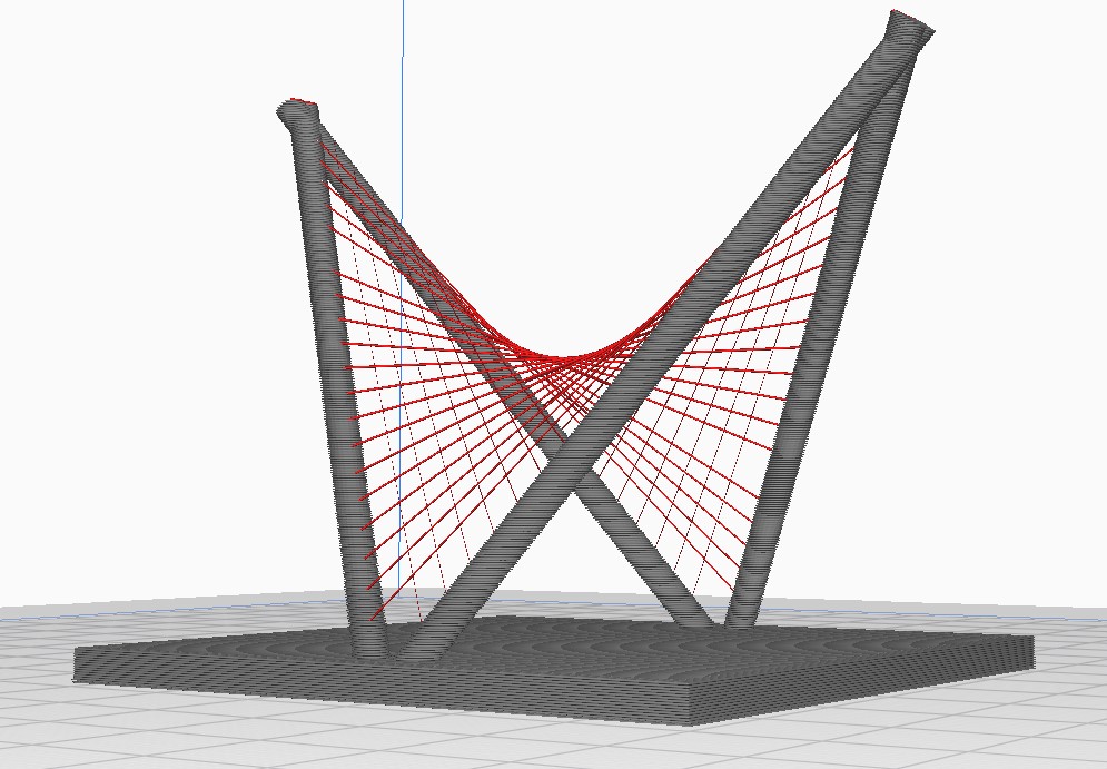
It's a pity I can't print it. I think I would need a 3D printer with a long noozle. Any idea?
gcode file: AG_hypar.gcode
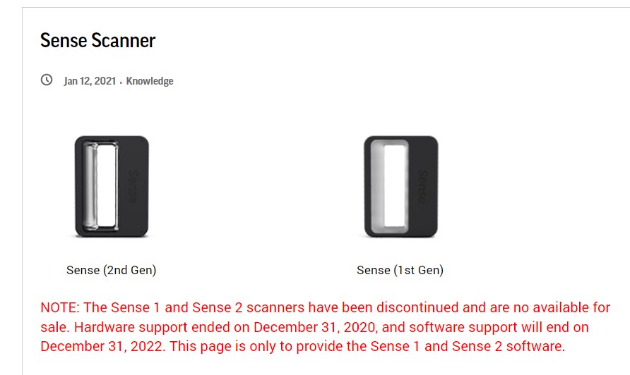
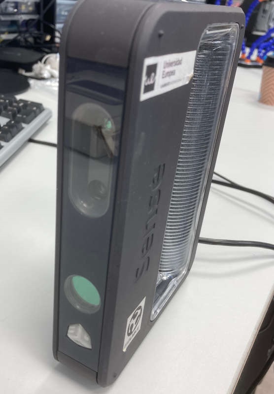
3D Scanning
We have some Sense scanners at the lab. They are discontinued but anyway you can download the software and work with them.
The software is simple, but the process always needs to refine and edit the result. In my case I wanted to scan my hand to test the controller handle on 3D.
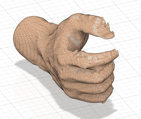
Dimensions are ok, and some details are very well caught. However nails and fingers need to be treated.
This is the file of the scanned hand.
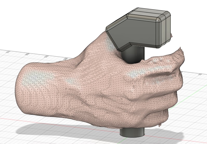
This is the controller 3d model with my scanned hand.