WEEK 05: 3D SCANNING AND PRINTING
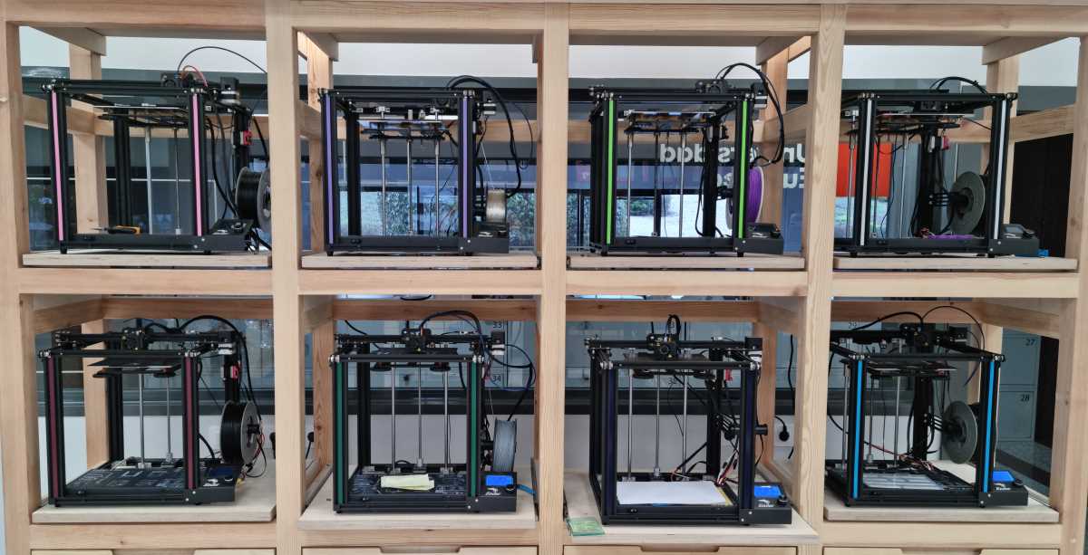
For this third group assigment, my "fabmate", Jon Merino, and I have to characterize the design rules for the 3D printer´s and scanners used, and available, here in FablabUE Madrid. In this case, we are going to use the Creality Ender-5 Pro , the Creality LD-002R UV Resin LCD, and the Sense 3D Scanner, which´s link we cannot supply because it´s out of commercial distribution. So, let´s start documenting!
- For this 5th week, we plan our time management for the GROUP ASSIGNMENT as follows:
- Document the Creality Ender-5 Pro: Apply all the possible design rules.
- Document the Creality LD-002R UV Resin LCD.
- For the INDIVIDUAL ASSIGNMENT , my planning will be:
- Design and print with the 3D printer an object that could not be made substractively.
- As for a second spiral goal: Apply 3D printing to my healthcare area of knowledge.
- Scan something with the Sense 3D Scanner, and print it.
GROUP ASSIGNMENT
3D PRINTING MACHINE PREPARATION: CREALITY ENDER-5 PRO
To start with this week´s assignment, we had a quick hands-on review of the Creality Ender-5 Pro , carried out by our instructor Alberto González, with the aim of being capable of detecting and solving all the possible printing errors:
Creality Ender-5 Pro SPECIFICATIONS |
|---|
| Machine Size: 552x485x510mm. |
| Print Size: 220x220x300mm. |
| Weight = 11.8kg. |
| Print Method: Online or TF card offline. |
| File Format: STL/OBJ/AMF. |
| Filament Diameter:1.75mm. |
| Number of Nozzle: 1. |
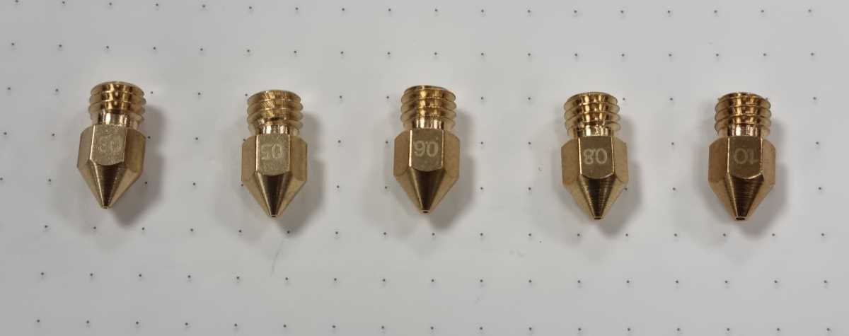
| Nozzle Diameter: Standard 0.4mm, Optional 0.2/0.3mm. |
| Slice thickness: 0.1mm-0.4mm. |
| Printing Precision: ±0.1mm. |
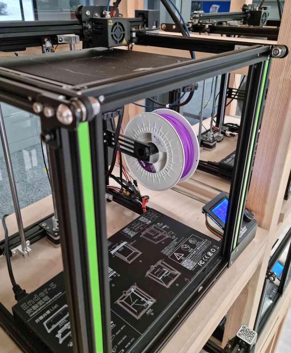
In order to being capable of ensuring a proper maintenance of the 3D printers, we learned the role of each component and we carried out a complete set-up that consisted in calibrating our printer´s build plate by adjusting the four wheels underneath (wheel left you raise it, wheel right you lower it). An easy way to calibrate the build plate is: by disabling the printer´s steppers, placing the noozle in one of the four corners of the plate, passing a paper between the noozle and the plate, and when you feel (and hear) the paper skim the noozle (by adjusting height with the weel below), you move to the next corner. Repeat 4 corners three times and finish adjunsting by placing the noozle in the middle of the plate and evaluating the same way.
Other two aspects you need to check when you´re a beginner, as me, is the extruder mechanism and the noozle, as we will check later, because they´re potetial points of filament obstruction.
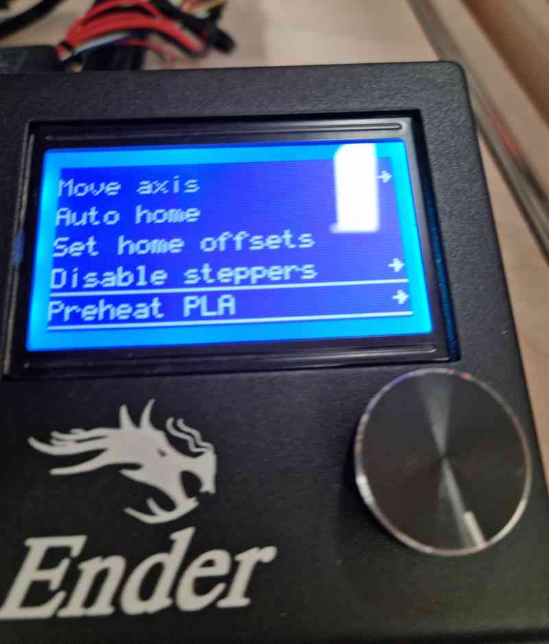 Disabling steppers
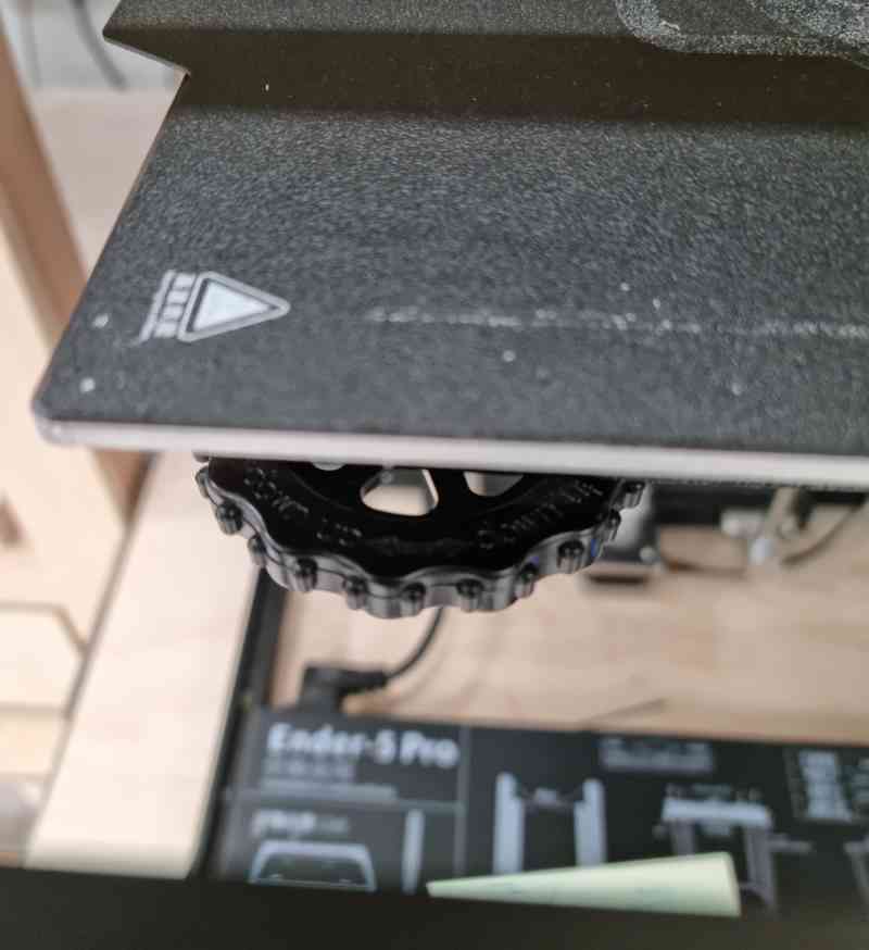 Build plate calibration
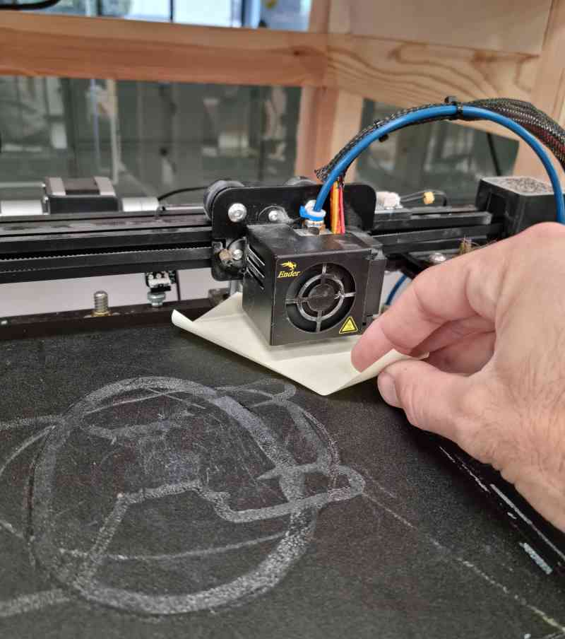 Calibration
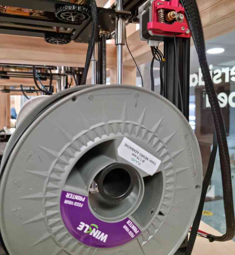 PLA filament
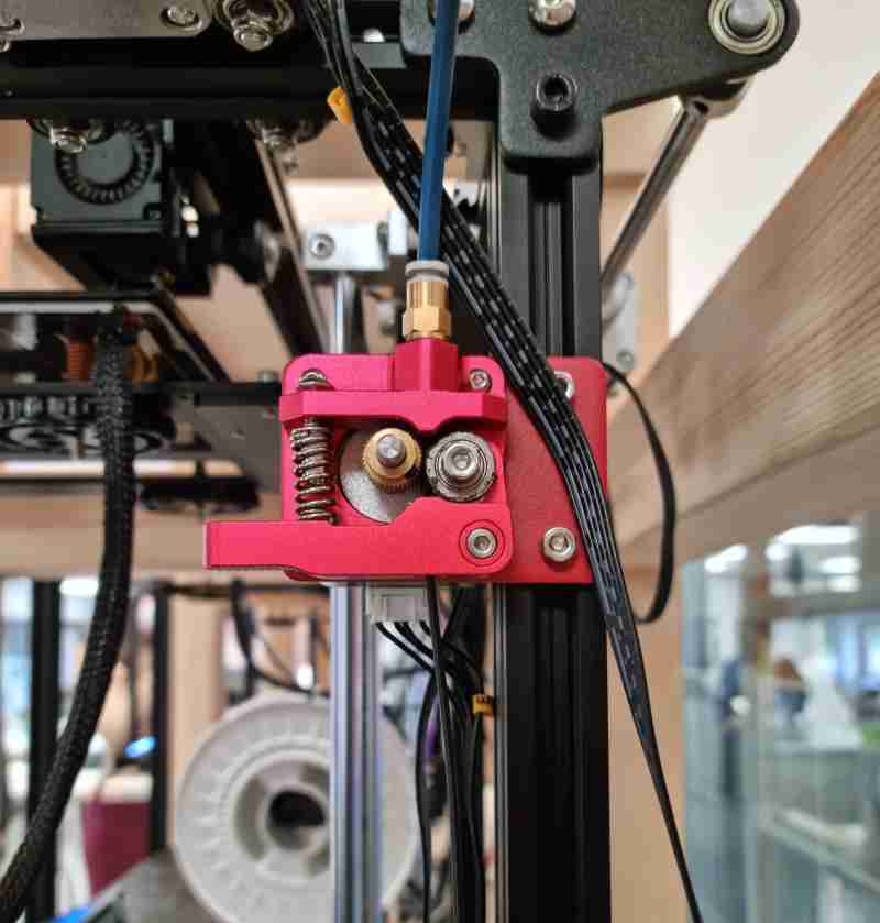 Extruder mechanism
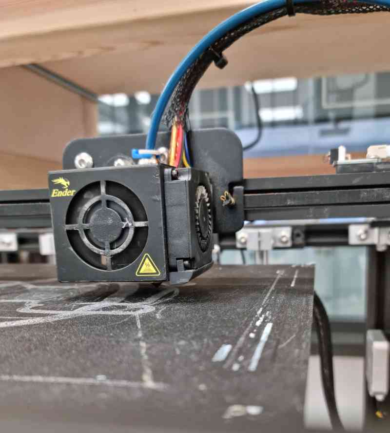 Noozle
Once the printer is running well, we need to load our .gcode design to the printer, in our case, we used the Ultimaker Cura printing software to load the designs and to configure the printer´s settings (you can find all the settings just ahead). Once prepared, we can preview our design ir order to make a final check, and just save it to an external microSD card. This card will be afterwards inserted in our printer, then we just open the desired .gcode and print it!
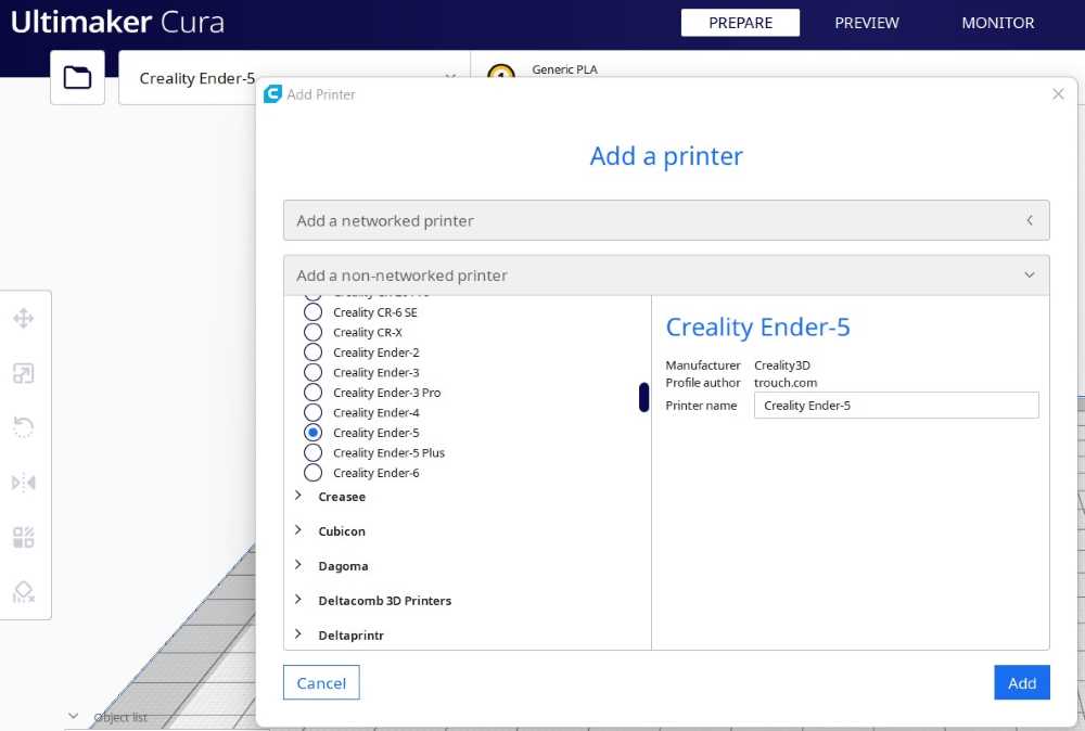 Adding our printer model
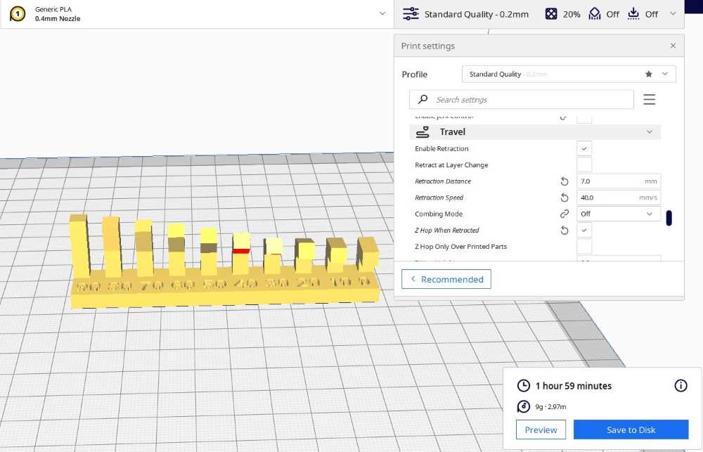 Printing settings
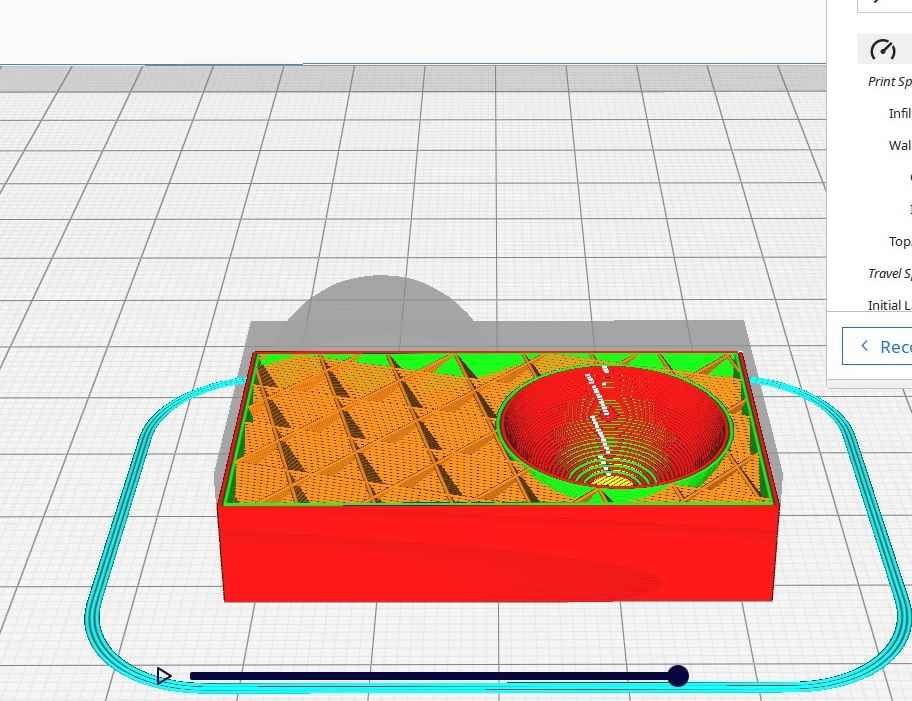 Preview mode
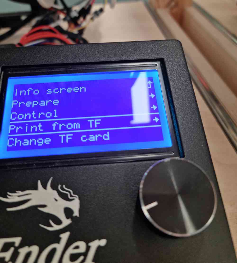 Printing from microSD card
Now that we know how our printer´s work, we started to print the different .stl files in order to identify what design rules fitted best. For all the first printing attempts, we used PLA filament, with 0.4 mm Noozle, and followed the same protocol:
| Pre-heated the PLA. |
| Uploaded the .gcode file. |
| Stay watchful until you´ve checked that the first layer is printed correctly. |
| Once finished, clean the plate and don´t leave anything in/on the printer. |
DESIGN RULES
As we had at our disposal nearly all of the Creality Ender-5 printers, we decided to do as many test as possible. Here you can check the specific settings for each printed design, and a resume of what went wrong and how we improved it:
OVERHANG AND CLEARANCE
- Speed = 40 mm/s.
- Printing Temperature = 205ºC.
- Build plate Temperature = 60ºC.
- Adhesion = Skirt.
- Support density = 15%.
 Clearance 0.2mm limit.
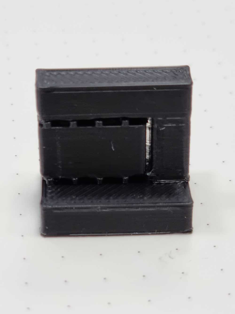 Ovehang supports.
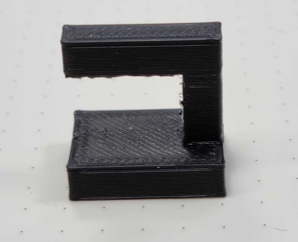 Overhang without supports.
For this first two objects with support, we printed first the overhang, because it was much smaller and less time consuming, and once checked that the settings worked well (we had to lower the support density from 20% to 15% to facilitate it´s removal without affecting the printed design) we printed the clearance .stl file. As you can see in the images, our clearance test resulted in 0.2mm limit.
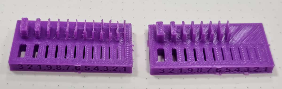
ANGLE, OVERHANG (WITHOUT SUPPORT) AND BRIDGING
- Speed = 40 mm/s.
- Printing Temperature = 205ºC.
- Build plate Temperature = 60ºC.
- Adhesion = Skirt.
- UNSUPPORTED.
- Travel: 7 mm/s distance and 50 mm/s speed.
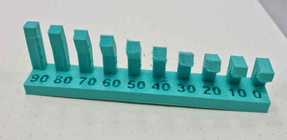
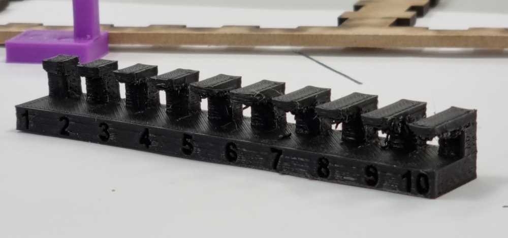 Overhang without support.
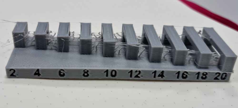 Bridging with stringing and .
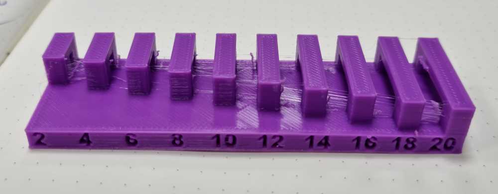 Bridging improved.
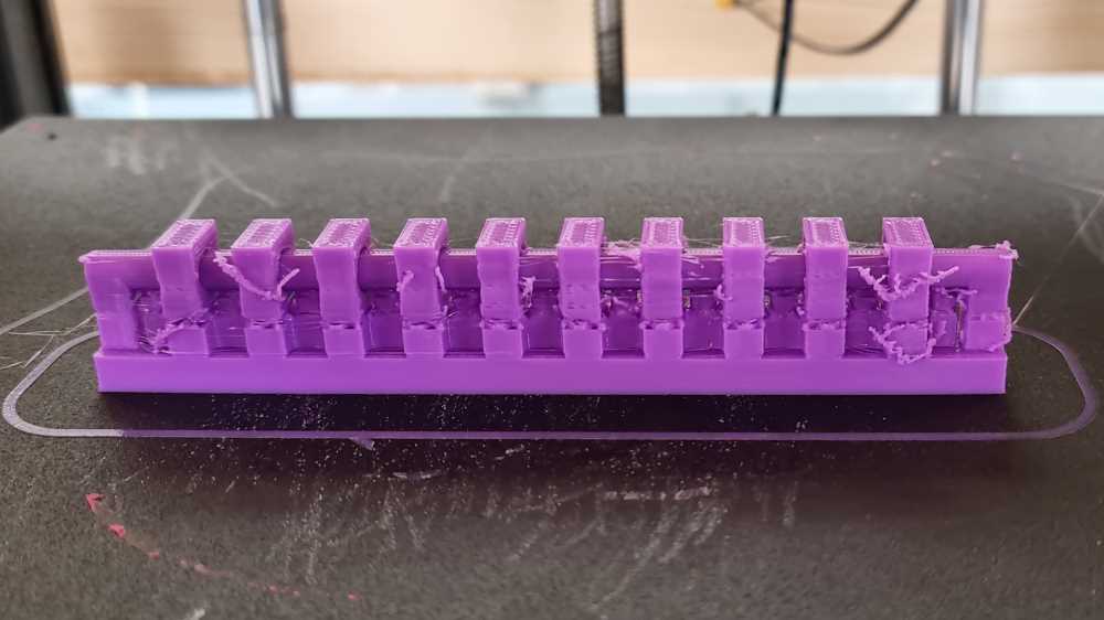
For the following designs, as you can appreciate (grey bridging) we had stringing, spaces between the walls and the fillings, and grinding. So, we lowered the speed to 40mm/s and changed the travel distance to 7 mm/s, and 50 mm/s speed. We changed the printing temperature to 210ºC, and activated Z hop, and obtained our best results, as you can see in the pinkish-purple bridging.
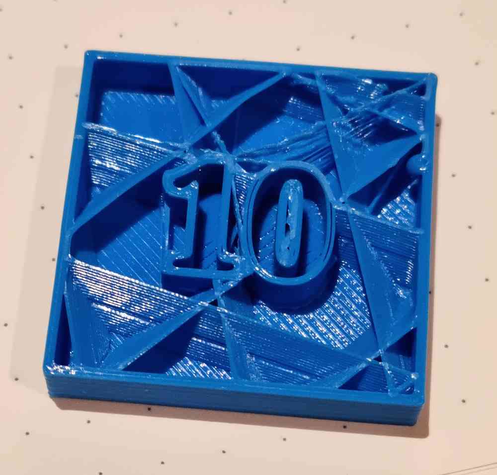
WALL THICKNESS
- Speed = 40 mm/s.
- Printing Temperature = 205ºC.
- Build plate Temperature = 60ºC.
- Adhesion = Skirt.
- UNSUPPORTED.
- Travel: 7 mm/s distance and 50 mm/s speed.
- Habilitate: Print thin walls
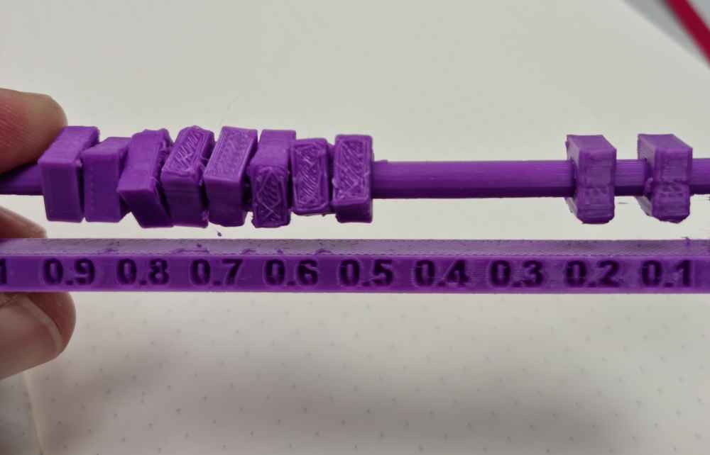
For the Wall thickness, in our first attempt, we obtained a minimum of wall thickness equal to the noozle size (0.4mm). To try to improve our results, we habilitated in the printing setting "Print thin walls" and obtained the second result.
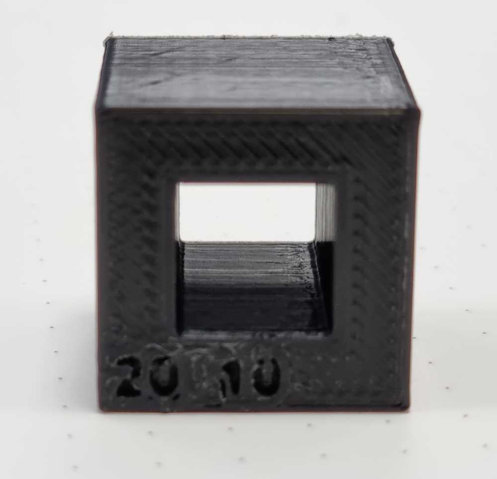
DIMENSIONS AND ANISOTROPY
- Speed = 40 mm/s.
- Printing Temperature = 205ºC.
- Build plate Temperature = 60ºC.
- Adhesion = Skirt.
- UNSUPPORTED.
- Travel: 7 mm/s distance and 50 mm/s speed.
 First anisotropy attempt.
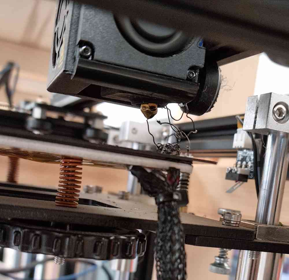 Extrusion obstruction.
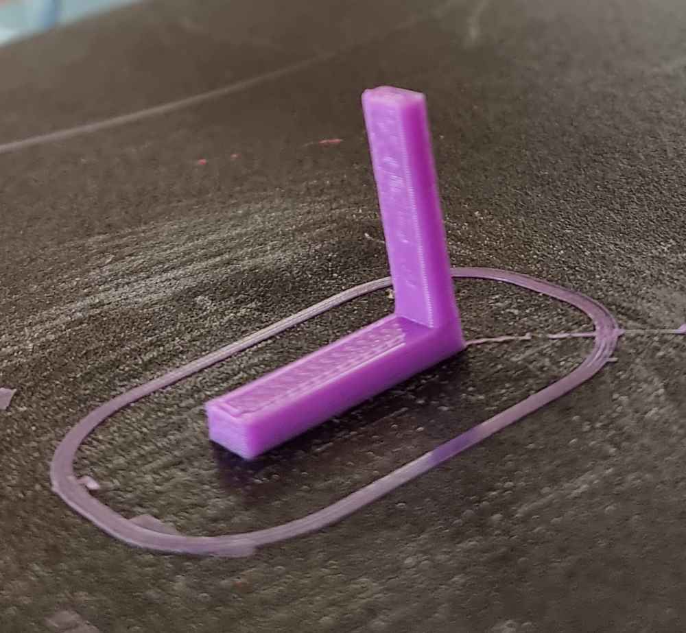 Second anisotropy attempt.
The dimension design gave no troubles as expected, as for the measurements, we had 19.9 mm external caliber and 9.8 mm internal caliber. Regarding anisotropy, we had some issues with the first printing attempt (black design), as we encountered extrusion problems, so after solving it, with the same settings, we obtained pretty good results (pinkish design).
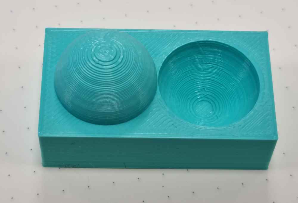
SURFACE FINISH AND INFILLS
- Speed = 40 mm/s.
- Printing Temperature = 205ºC.
- Build plate Temperature = 60ºC.
- Adhesion = Skirt.
- UNSUPPORTED.
- Travel: 7 mm/s distance and 50 mm/s speed.
 Infill 10%.
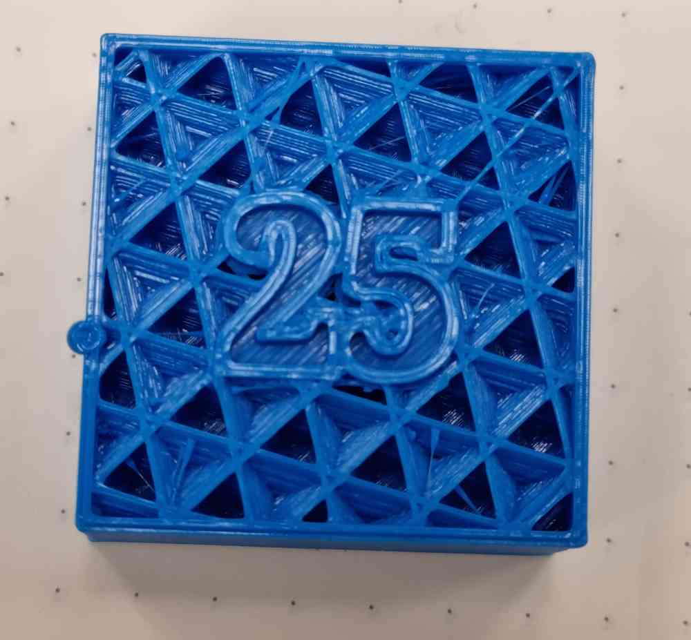 Infill 25%.
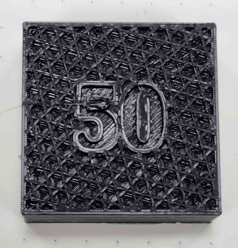 Infill 50%.
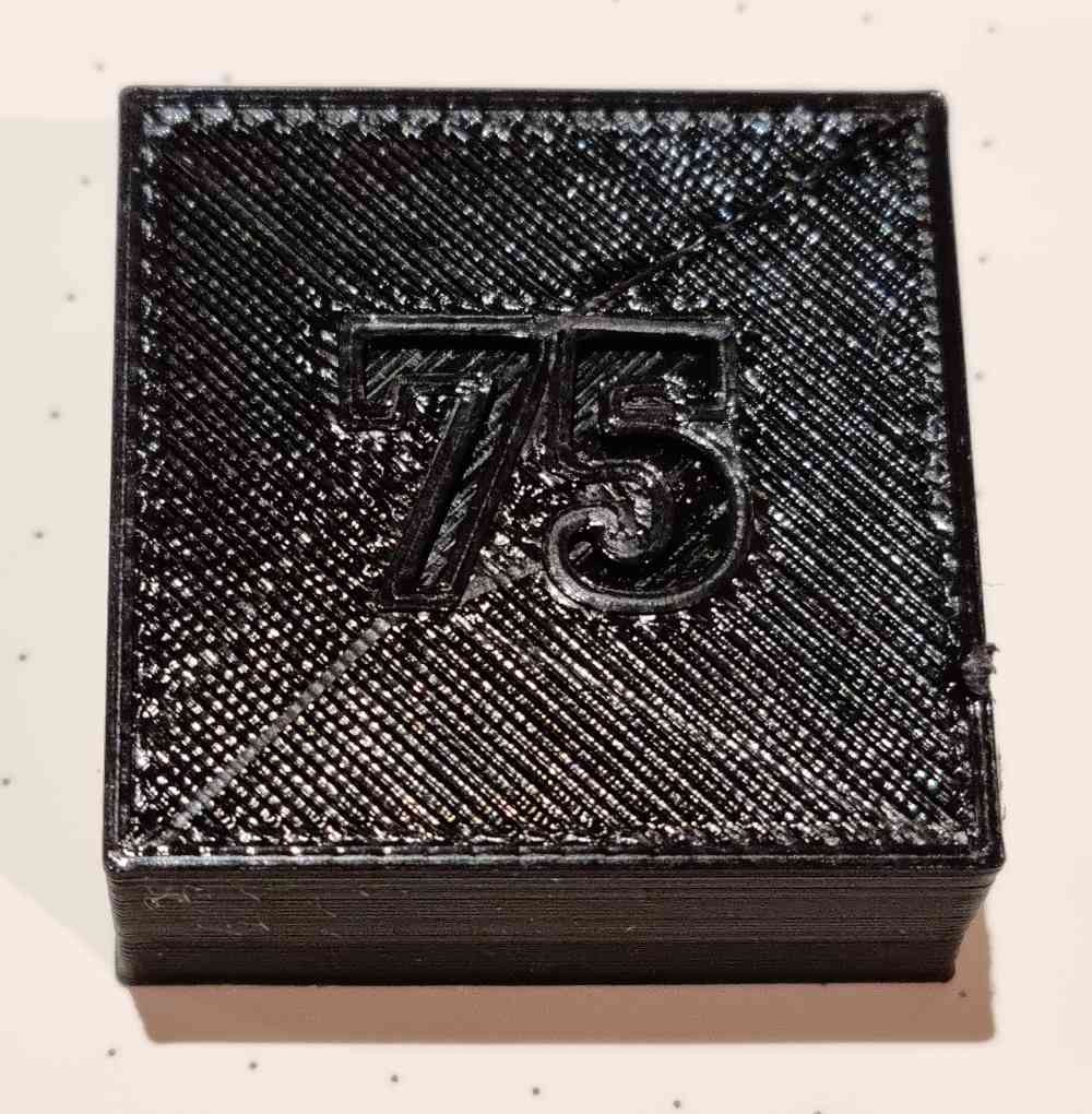 Infill 75%.
As for the final tests, surface finish and infills, they worked pretty well, but we learnt that for next time black PLA doesn´t suit well for taking photos. Regarding the infill´s as we learnt, 50% infill should be enough for most of the 3D printing we´re going to make. As a conclusion of my final thoughts, I had some previous experience with 3D printing, but I never imagined it had so many possibilities, it´s incredible how you can set the same 3D printer in many different ways depending on what you want to print. In my case, 3D printing is going to have a lot of weight in my final project.
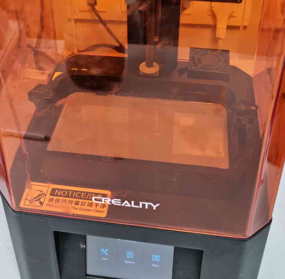
3D PRINTING MACHINE PREPARATION: CREALITY LD-002R UV RESIN LCD
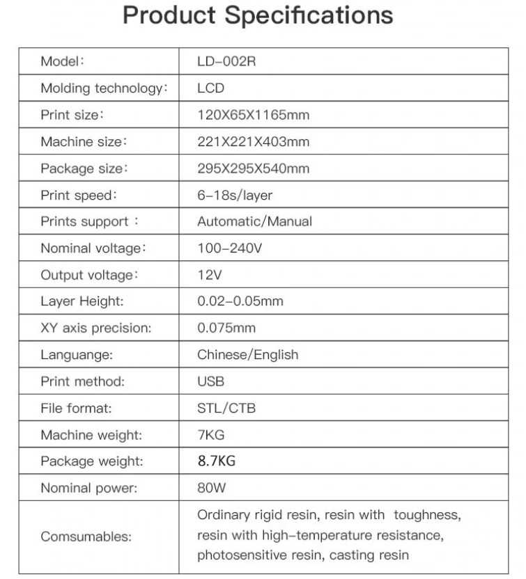
As for the second 3D printing machine, we tested the Creality LD-002R UV Resin LCD:
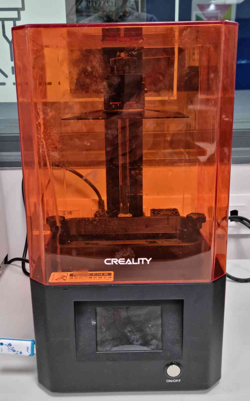
This was the first time we used a resin 3D printer, so these are the steps we followed:

| Install Chitubox software:And configure your resine printer. |
| Open in chitubox your .stl file. We tilt the figure 45º to assist the process. |
| Configure your resine properties in the printing settings. In our case, the resine used specifications were: Bottom exposure 60s, Normal exposure 8s. |
| Configure supports and press: + All. |
| Check slice and chek the weight: Depending on the weight we will add a specific ammount of resine in ml. |
| Save your .ctb file on the USB: Open it on the printer, and print! |
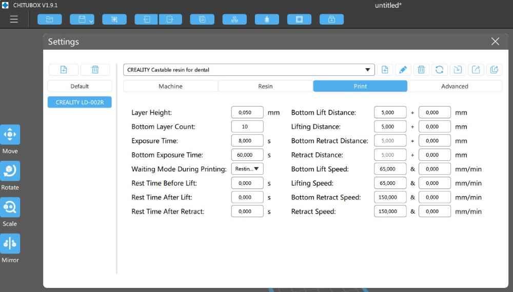 Printer settings
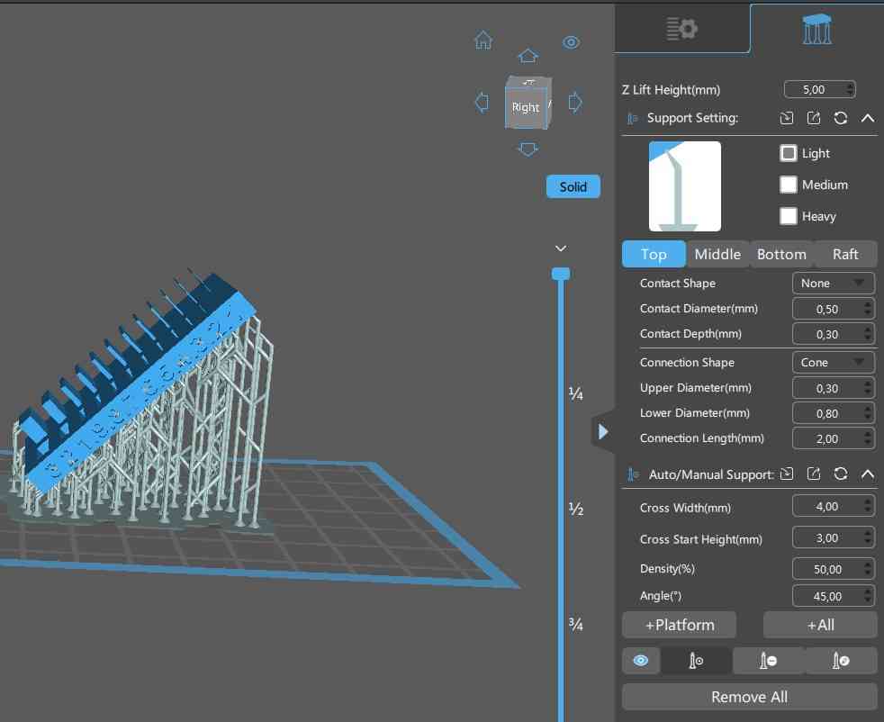 Support configuration
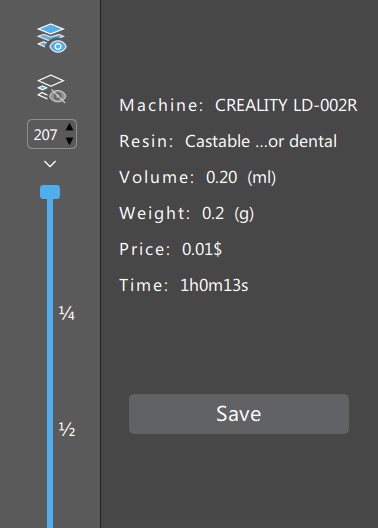 Weight and resine volumne
Once the file is ready, you just need to fill the vat with the specific ammount of resine, close the cover and print. Don´t forget to check that the screen at the base of the vat is clean! It´s mandatory to maintain safety procedures, by wearing gloves during the resine manipulation and having a toxic waste container. Once the process finishes we need to go to the next stage, were we will inmerse the piece in .... for 10 minutes, and after 10 more minutes in water.
We can take advantage of this time and clean the resine that´s in the vat filtering it back to the resine bottle. After the "bathing" finishes, we set our piece to "dry" for 10 more minutes, and at last, our piece is finished!
 After filling the resine.
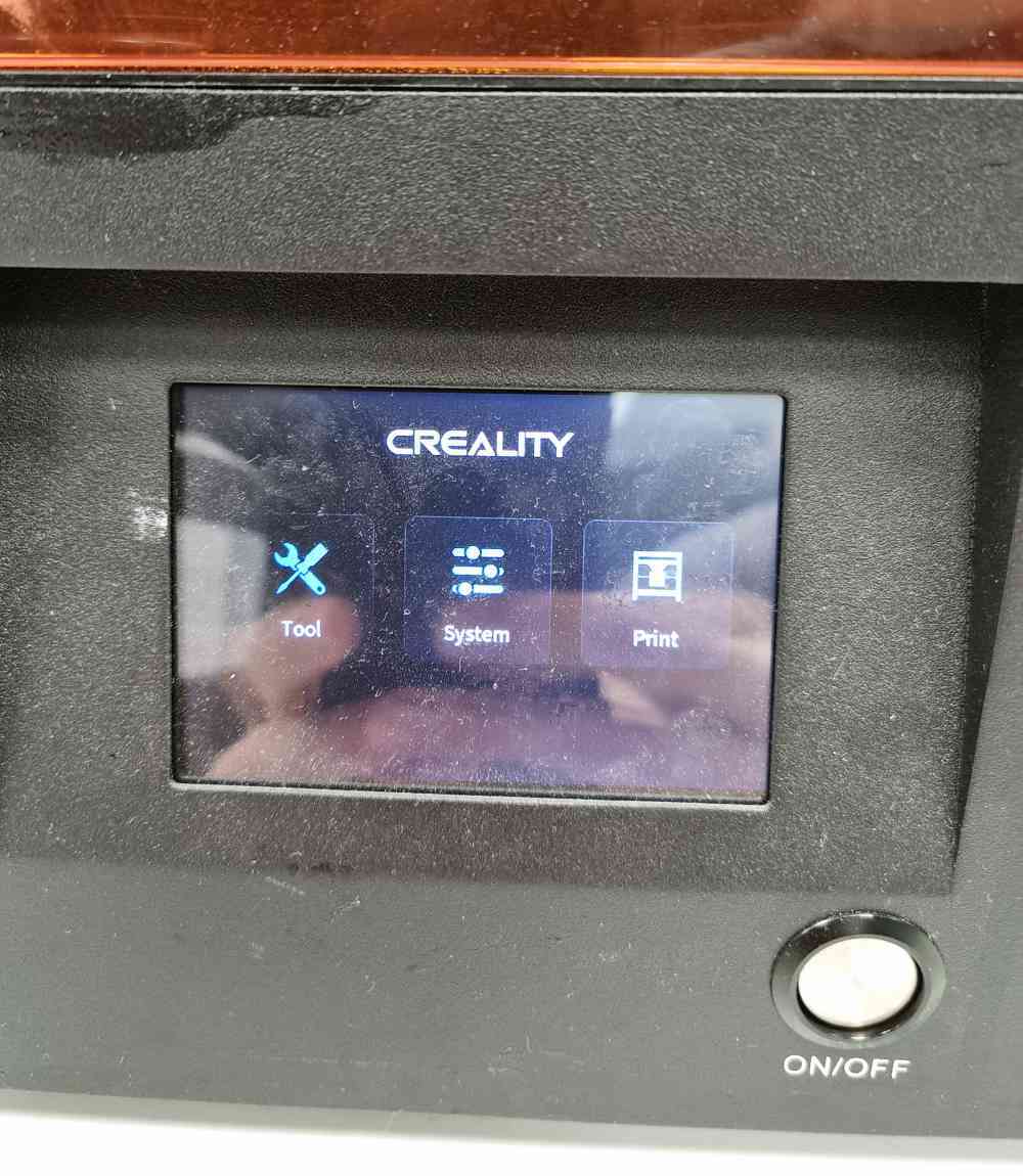 Starting to print.
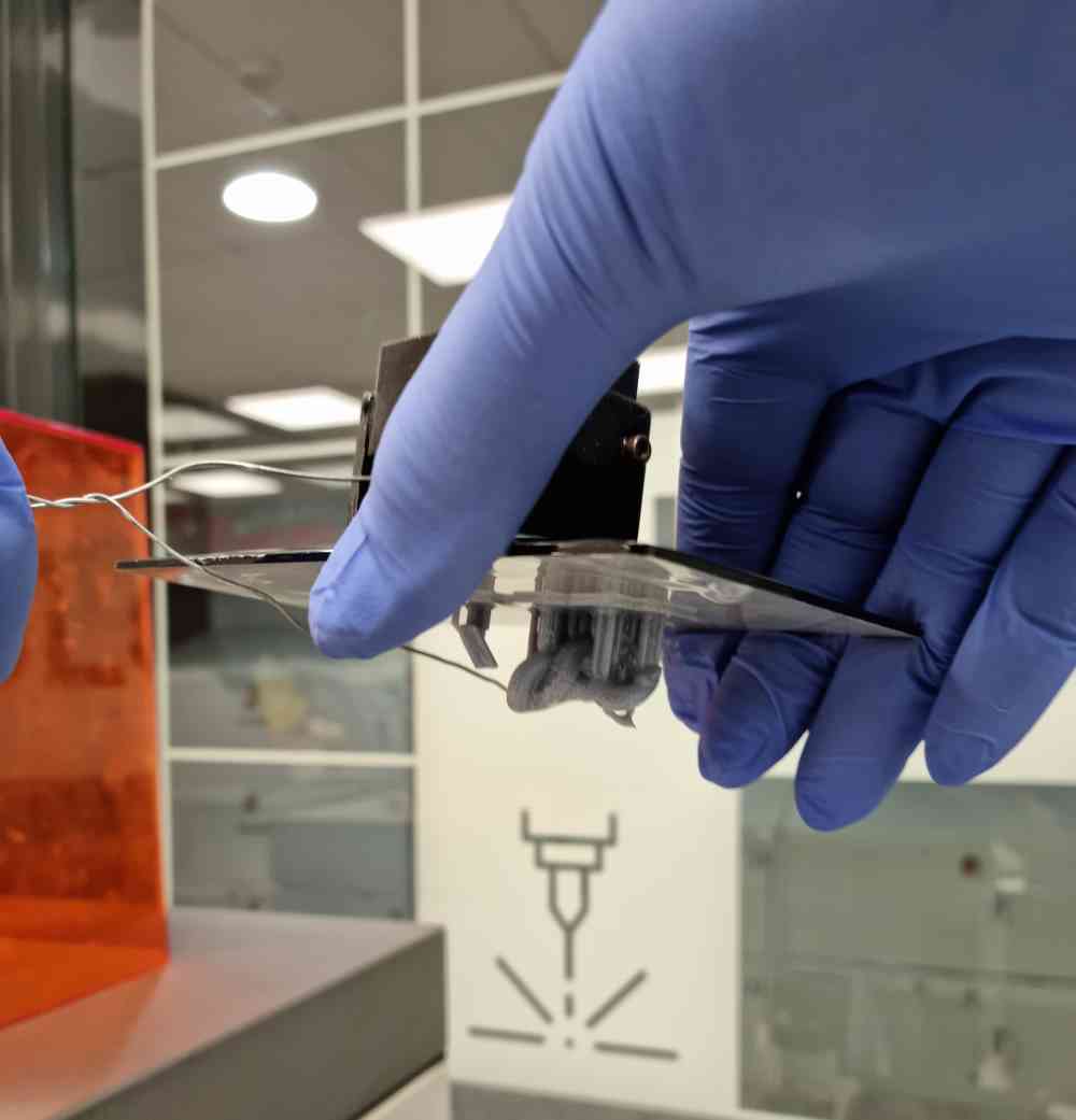 Removing the piece from the printer.
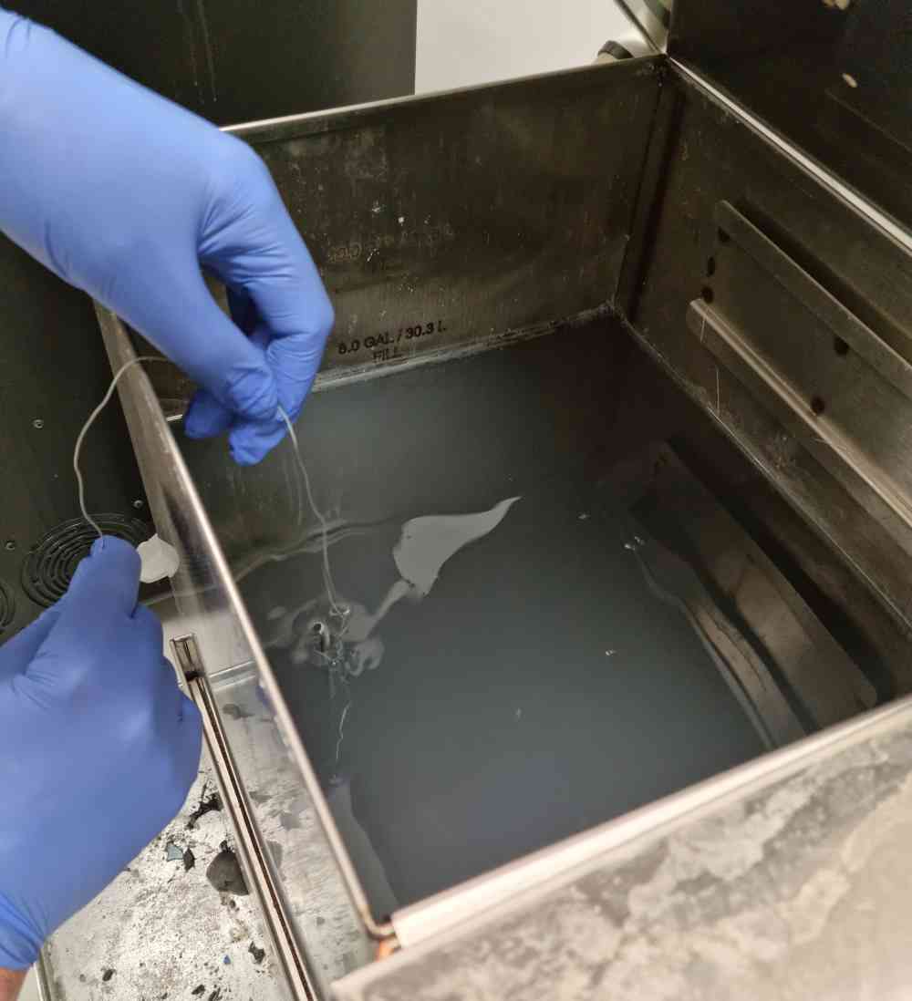 Rinsing the model.
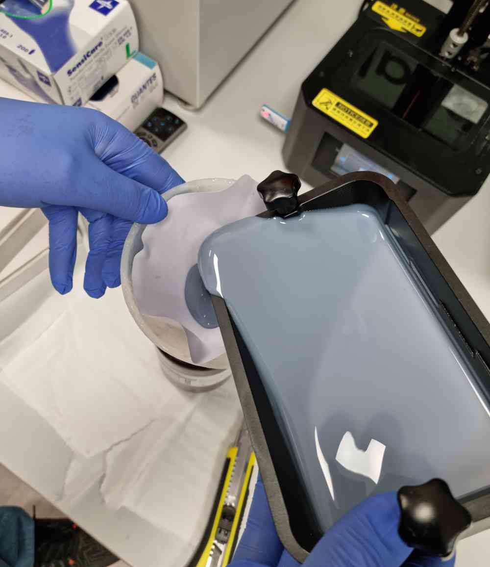 Cleaning the vat.
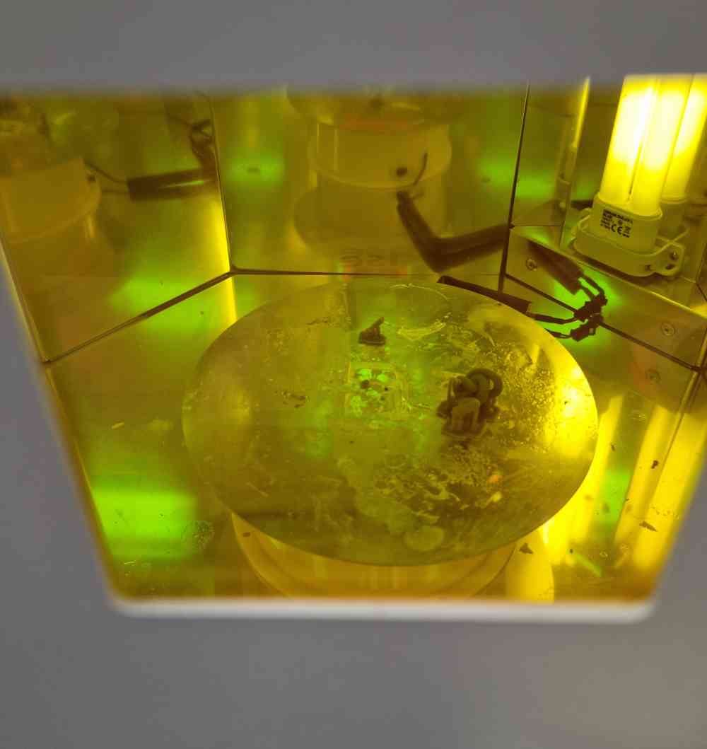 Final 10 minutes.
And finally, our first examples. We have to say that we scaled a lot one of our pieces because if not, we woulnd´t have had it in time. It´s the thickness .stl that we used in the Creality Ender-5 and you can clearly see the difference between both 3D printing techniques, I can´t believe that the resine printing has so much precision and detailed finishes. The other one is part of my individual designs, a small Voroni Spere I created, that with that size it´s impossible to print with PLA filament and 0.4 noozer.
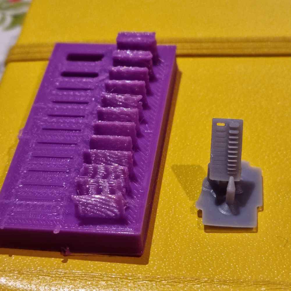 Difference between both 3D printing techniques.
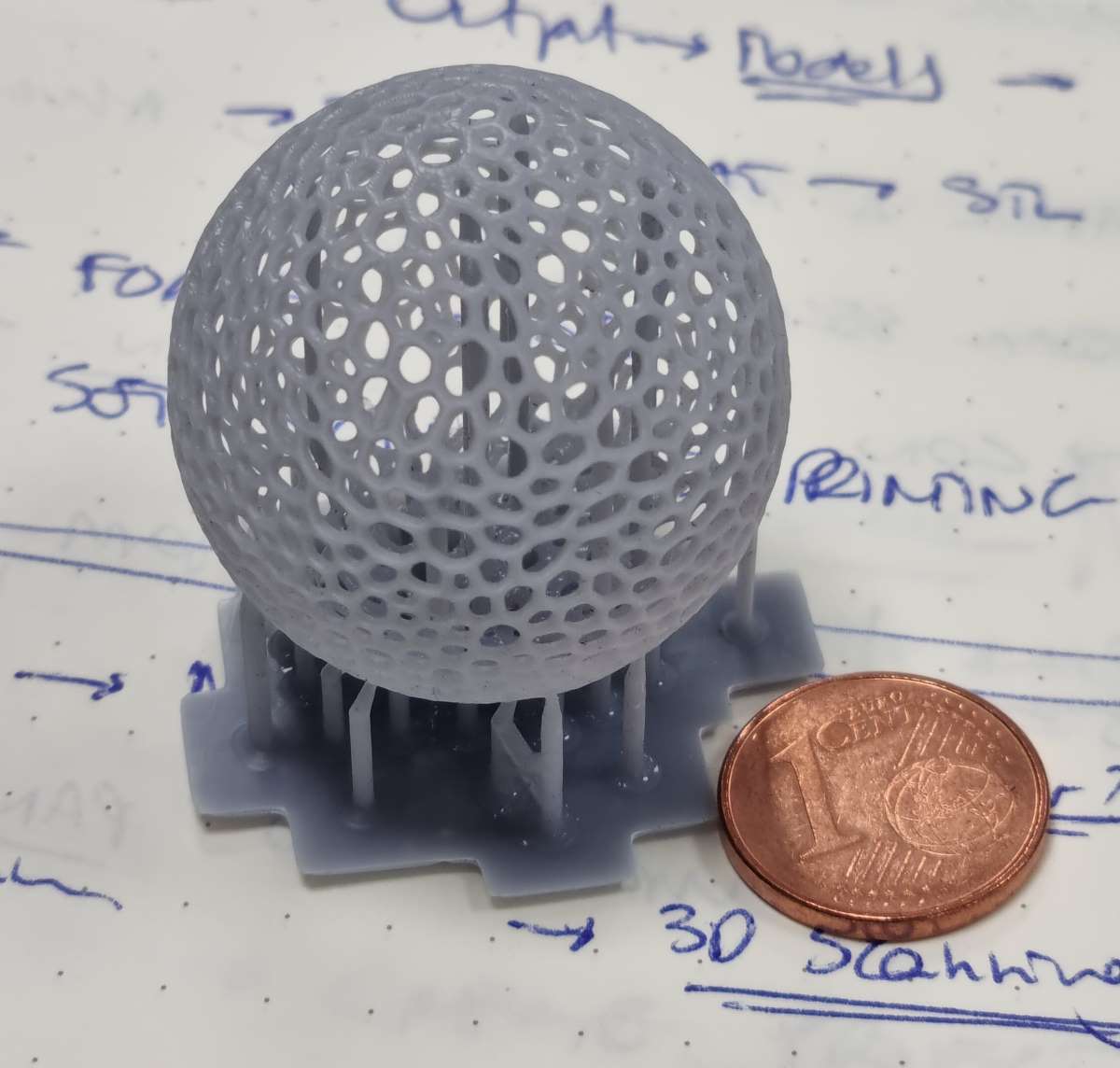 Resine precision and detailed finishes.
As for the final thoughts with the resine printer, it´s very easy to prepare the file, but the whole process it´s a little laborius, were you need to be careful when you manipulate the resine. Even do at first I didn´t feel comfortable with this kind of printers, the quality and precision of it´s finishes is amazing, and can offer you a completely different approach to what traditional 3D printers do. So, i´m glad we used this machine!. For now, this week is completely different from the others, i´m not feeling that intense uphill climbing at the beginning, on the contrary we´ve been non-stop printing and accumulating practice hours instead.
INDIVIDUAL ASSIGNMENT
Design and print a 3D object
As I´m a healthcare researcher and professor, I heard of the possibilities of 3D printing medical images such as MRI, TC and 4D ultrasonography due to the fact they support DICOM files. A type of file that can be transformed, once edited, to .stl files. So, after a few minutes of searching in the web I found 3D Slicer, a free, open source, image computing multi-platform used for medical, biomedical and, related imaging research.
It has an incredible online documentation, and with the help of some easy DICOM to 3D printing anatomic segmentation tutorials , you can quickly get hands on. In my case, I wanted to try to select a specific anatomic structure from a CT (Computed Tomography) to 3D printing.
DICOM to NRRD file CONVERSION
The MOST IMPORTANT FEATURE that 3D Slicer has, in my opinion, is that it allows you to CREATE a NRRD file from a DICOM file. This is a key feature because NRRD files contains NO patient information and are thus a safe way to work and send image data without compromising patients privacy.
Here you have the tutorial of How to create a NRRD file from a DICOM Medical Imaging Data Set. with 3D Slicer. Or, you can always use the sample data that 3D Slicer has in it´s sofware which, by the way, is wide enough to generate a multitude of models.
So, this is how it went:
| Open 3D Slicer software and open and load .NRRD data.In my case, in order to help replicate my first experience I selected the CT-Chest sample data. |
| Go to modules -> Volume Rendering: Select display preset as desired. I selected CT-Bones. Enable Crop and Volume and ROI visualization so the anatomic segment appears on the top left quadrant. |
| Now that we have our file ready and visible, you can shift left and right to obtain the best view of the segmnet.You can also narrow down the view with the small sub-menus you´ve got on top of each image layout. |
| Go to segment editor and ADD as many parts as you want to differentiate. |
| We need to give information to the software regarding the boundaries of each segment. You just need to add SEEDS by using the paint effect in order to help the software demilitate them automatically after. |
| Now that the segments are delimitated:Apply GROW from SEEDS so the software will complete automatically the segments delimitatios. |
| Go to Segmentation module to prepare your export file:Set operations to Export and output to Models and press EXPORT. |
| Finally go to file -> save:Change the selected files to .STL format! |
| You can open your new .STL file on your 3D printer program. In my case I opened it with the Ultimaker Cura, or you can edit your file before printing. |
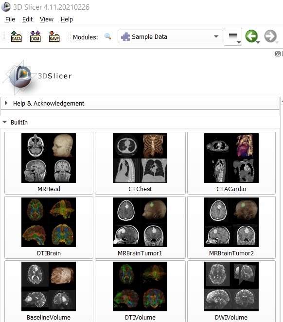 Select sample data.
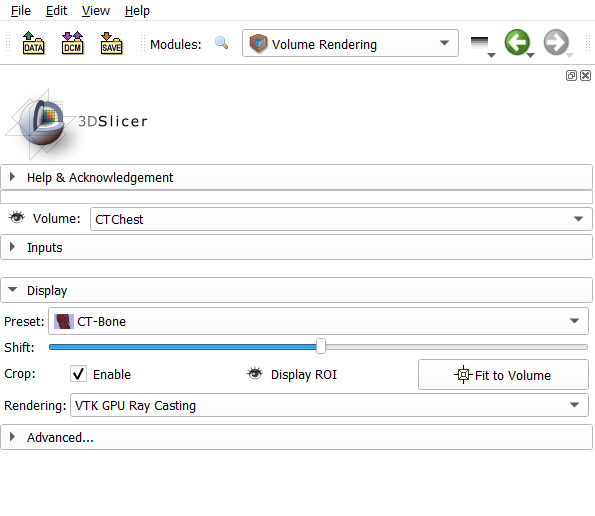 Volume rendenring module.
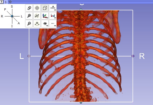 Editing segments.
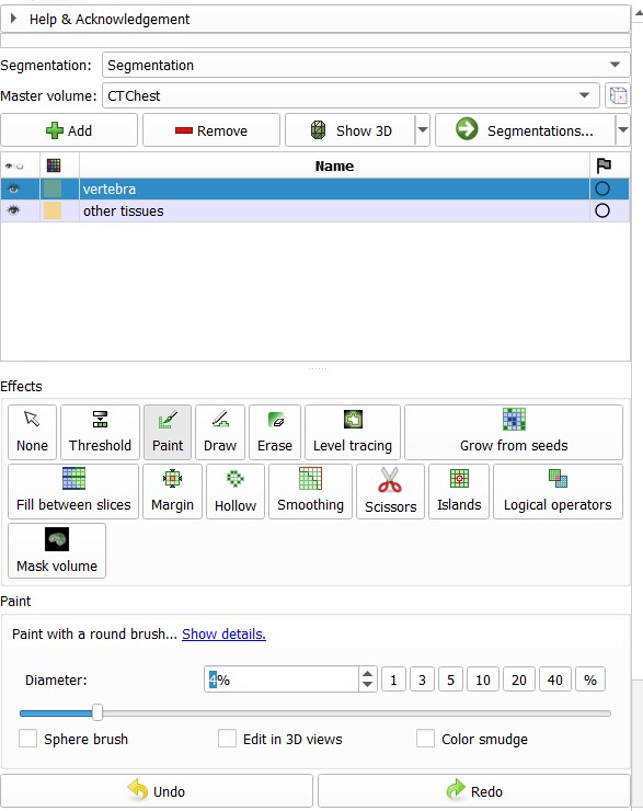 add SEEDS.
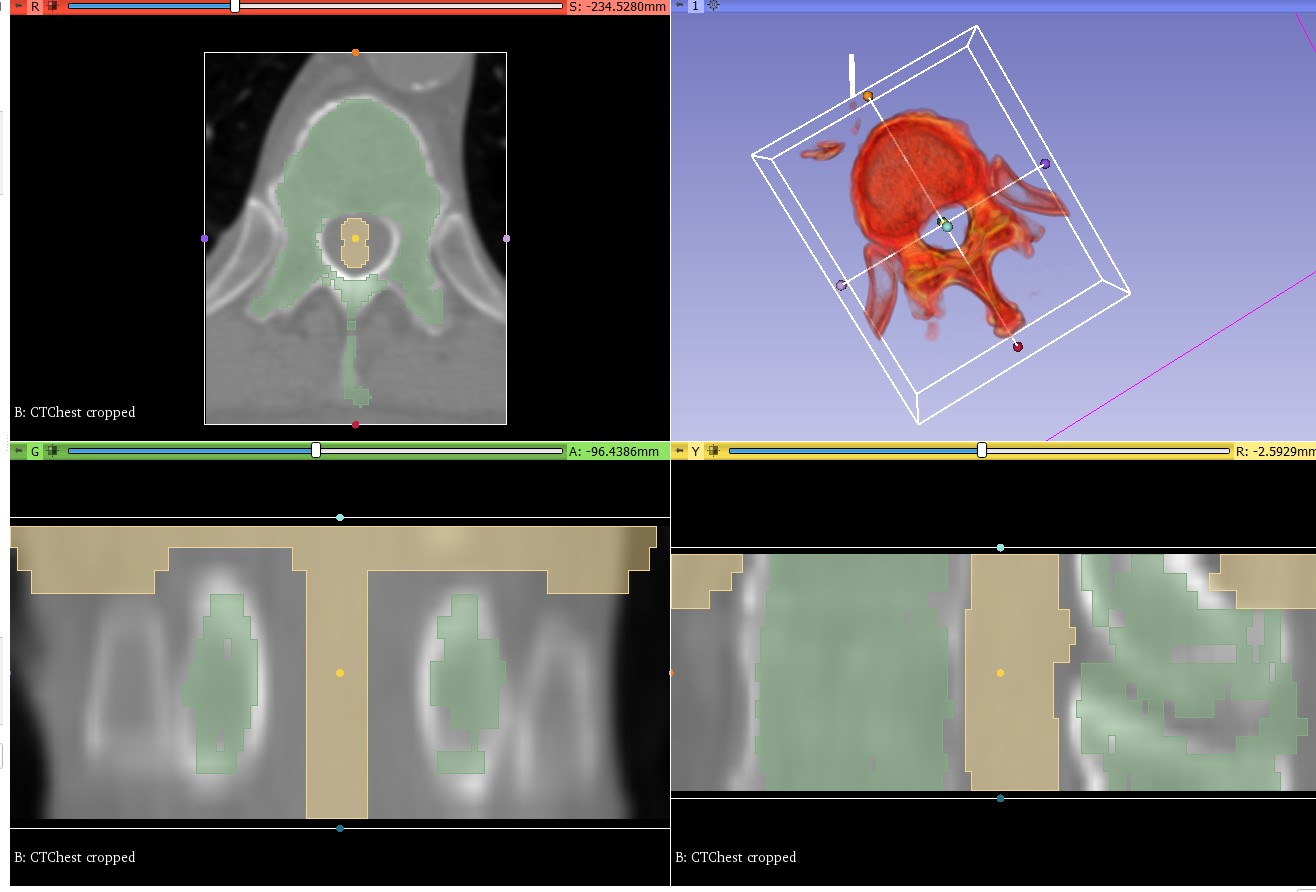 Growing Seeds.
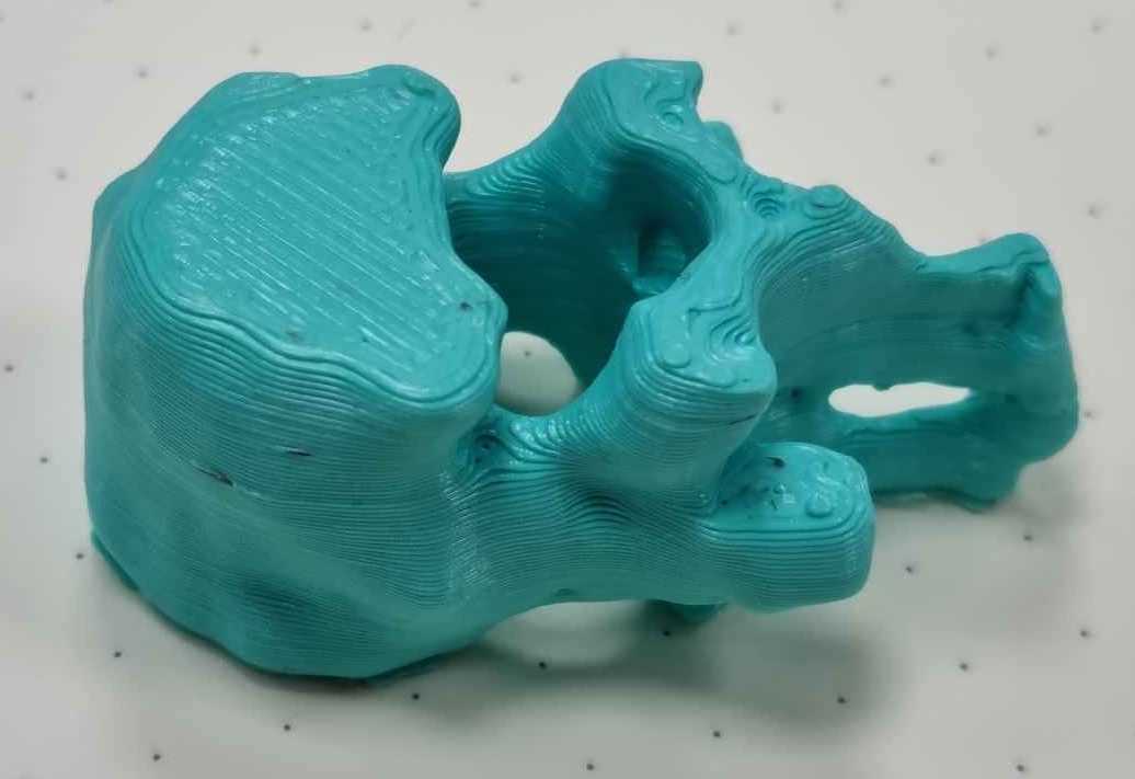
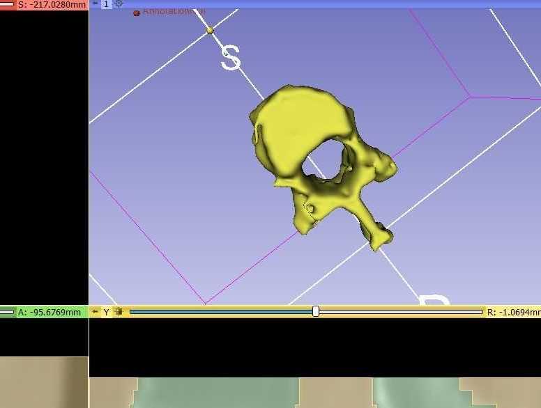 Final anatomic segment.
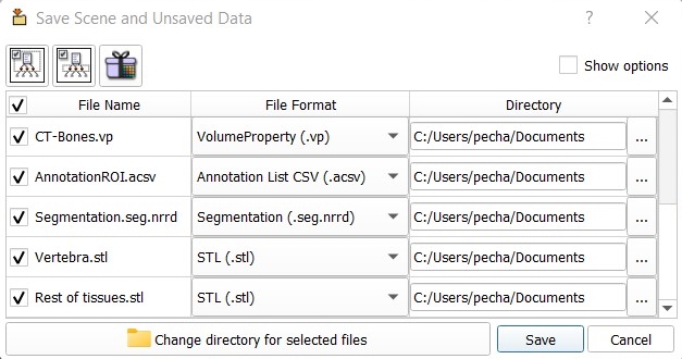 Export file.
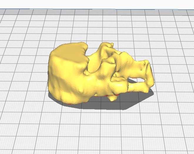 Printing file.
Here you can check a couple of videos:
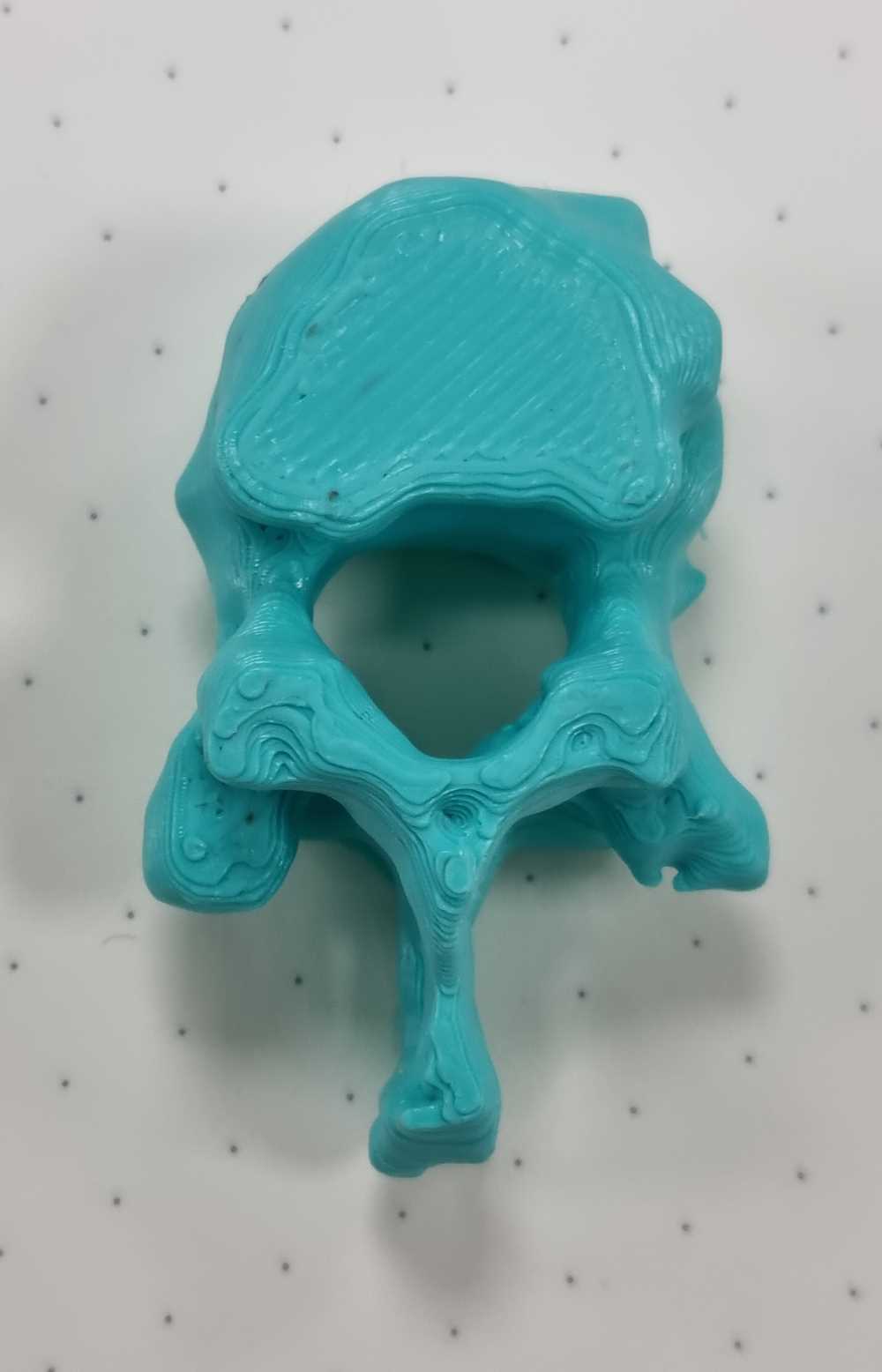
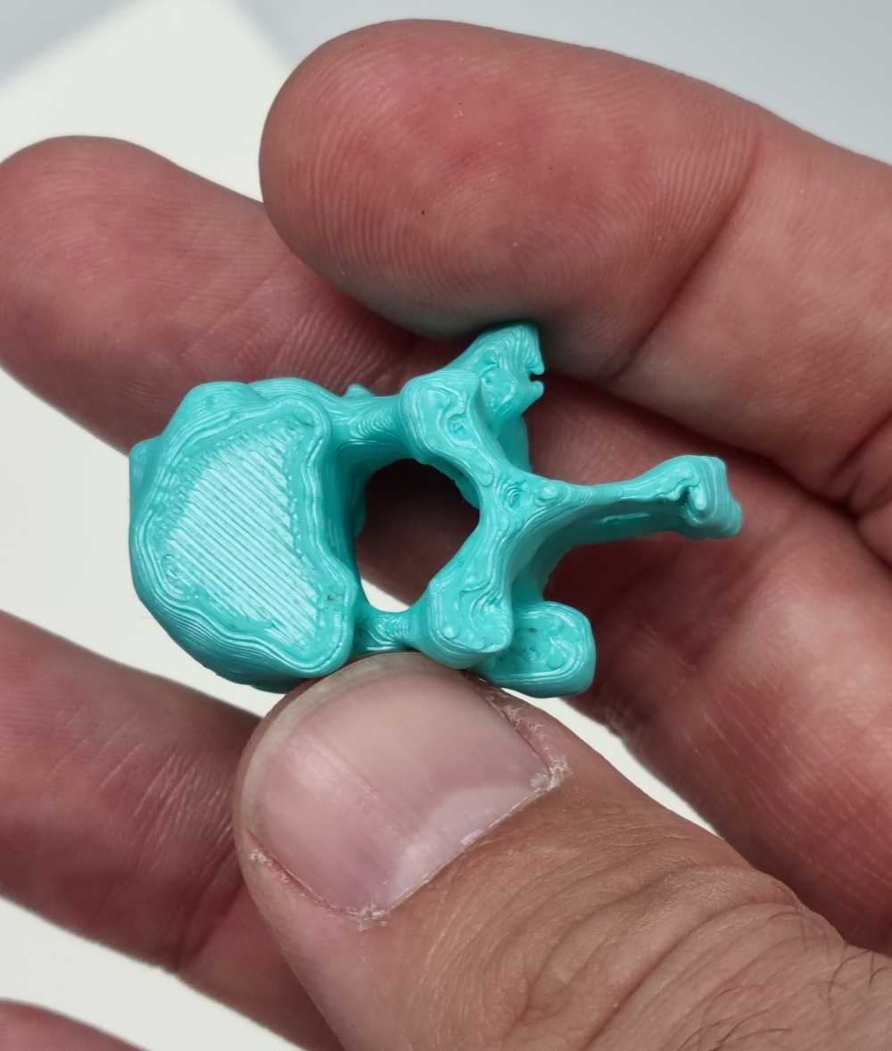
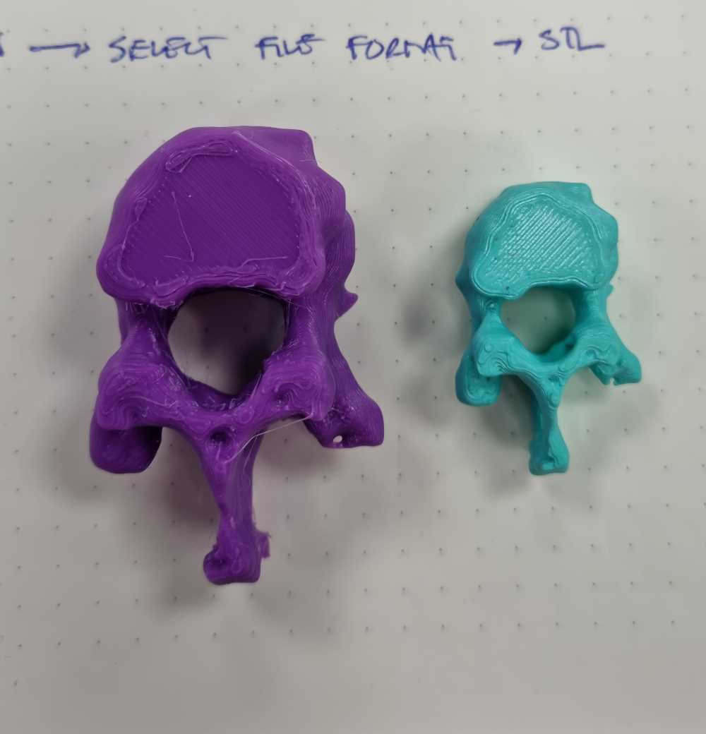
Surprisingly it worked very nicely, and I have to say that i´m amazed with this program and the incredible possibilites that it´s going to bring to me. It will help me apply, in a practical fablab way, a transfer of knowledge applying digital fabrication in healtcare programs. Here below you can check the final designs I printed. I started with a scaled version just to see that it printed well, and then printed a bigger version.
PRINTING SETTINGS
- Speed = 50 mm/s.
- Support density = 15%.
- Printing Temperature = 205ºC.
- Build plate Temperature = 60ºC.
- Travel speed = 70mm/s.
- Retraction distance = 5 mm.
- Retraction speed = 45 mm/s.
- Z hop = 0.08.
- Adhesion = Skirt.
As the .stl file is quite heavy, you can download all of the at the bottom, as they´re compressed in a .zip file.
Editing objects with MeshMixer
As for the last step with the 3D printing I wanted to edit objects with the Autodesk Meshmixer, a progam I´ve never used before. I haven´t got much time to use it, so i´m going directly to modify the pattern to a Voronoi stile in a sphere and in half of the vertebra I just designed. To modify the sphere´s pattern you just have to go to make pattern -> Dual Edges pattern type -> Tiling Mode: Hex Grid, and finally, adjust the element dimension as wished. On the other hand, modifying half the vertebra is more challenging, and this is what I did:
| Select the halve of the vertebra that we want to edit. |
| Divide the vertebra in two parts: Edit -> separate and the select only the part to modify. |
| Before modifying the pattern, we have to reduce the shape preserving: I changed the percentage to 90%. This will simplify the Voronoi pattern we´re going to make after. |
| Go to edit, make pattern (pattern type = Dual Edges), and Tiling mode = Hex grid. Adjust element dimension as wished. I adjusted it to 1.0. Don´t forget to accept the changes! |
| Now we have to combine both parts, but before we select the non-modified part of our object and fill flat the contact surface: Edit -> Replace/fill -> Flat minimal. |
| Now that both parts are edited, we need to re-combine them: Select both parts, and combine. |
| Finally, export file as .STL. |
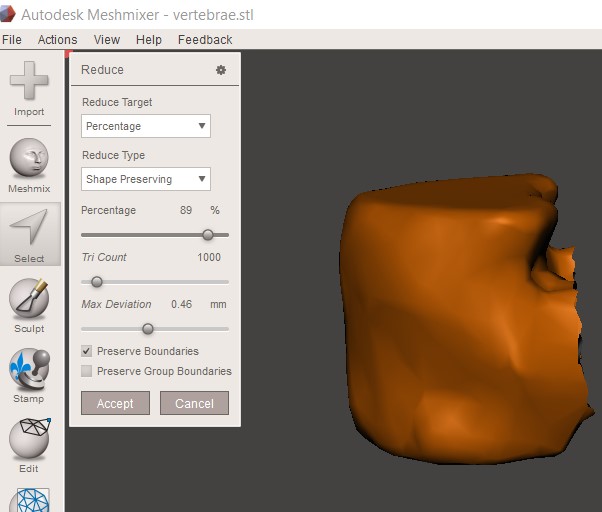 Reduce surface.
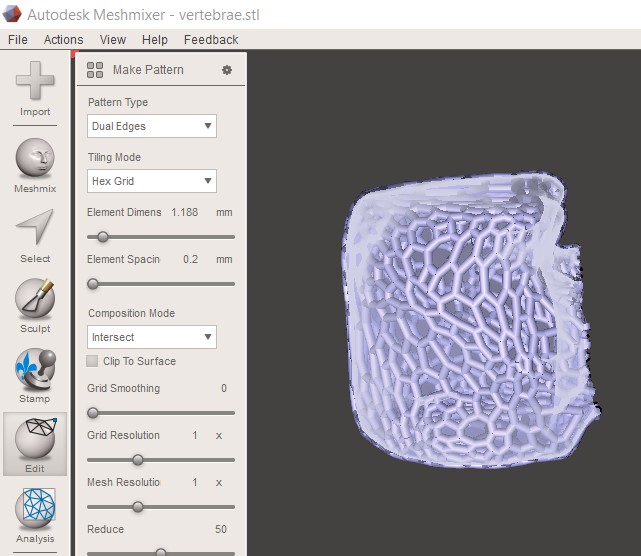 Apply pattern.
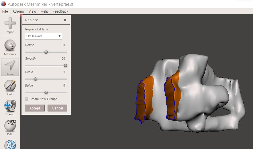 Fill flat.
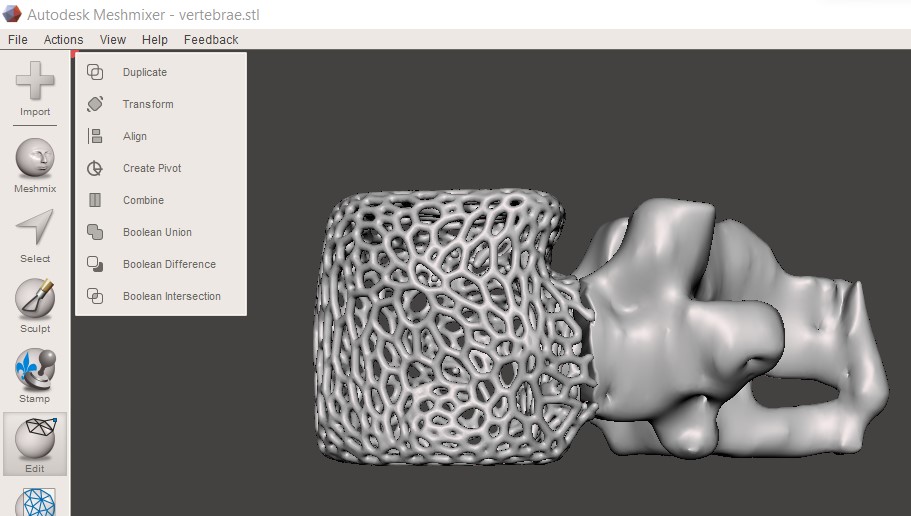 Combine.
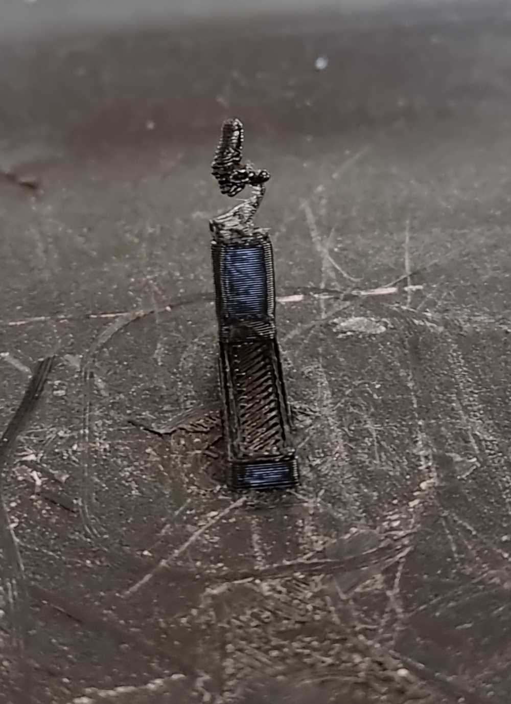
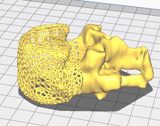
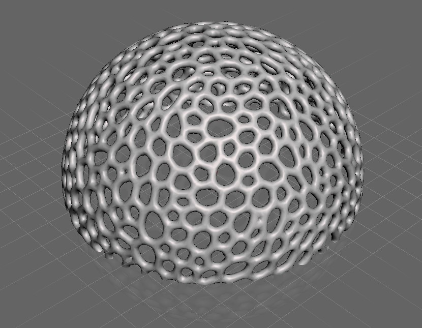 Voroni pattern with Meshmixer.
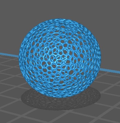 Extrusion error with PLA.
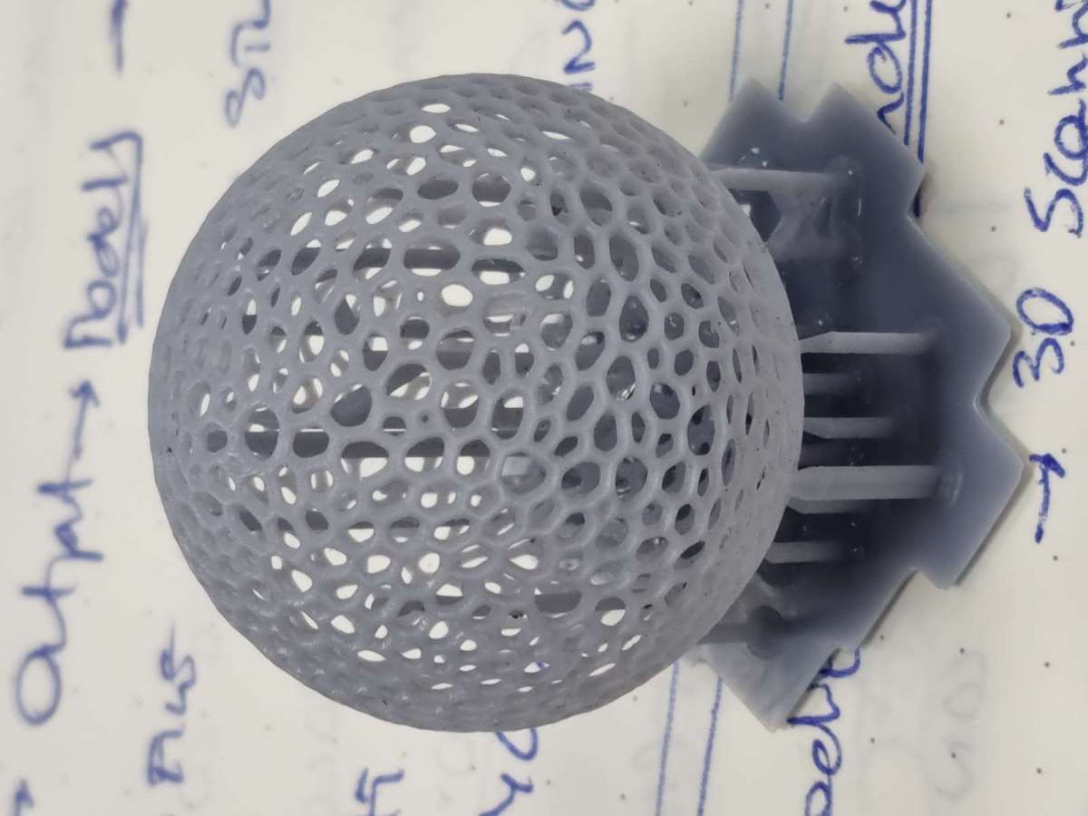
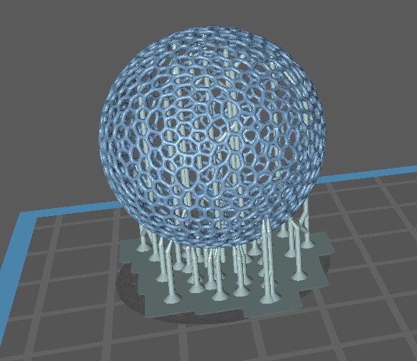 Resine Supports.
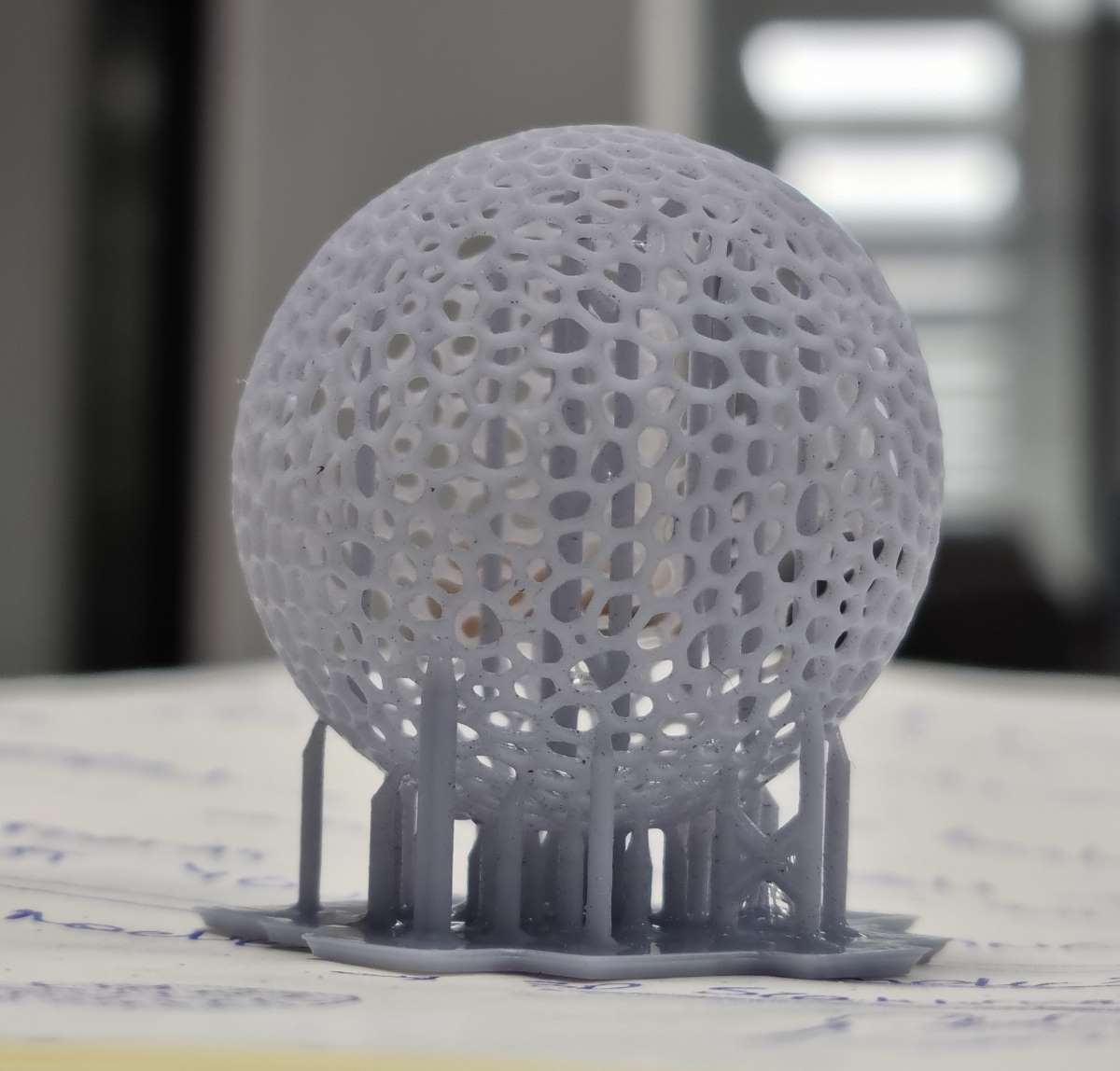 Resine Voronoi.
Changing the pattern to Voronoi at first looked easy with the Meshmixer, after the problems came.. I didn´t realize how thin was the thickness of my walls, so, it didn´t matter how many times I changes the settings of the printers, it just stopped printing at half way. But then, when I printed with resine the Voronoi Sphere and had a close look at the object I realized that it was way much thinner than expected. So I checked the thickness and I made sure that the minimum was 0.2 mm wider than my extruder, and finally I was succesfull even do I had stringing and that the object printed was quite small! At the time I finished documenting this assignment, the Voronoi patterned vertebra resine printing hasn´t finished yet, so i´ll update it later.
 Voroni Resine sphere.
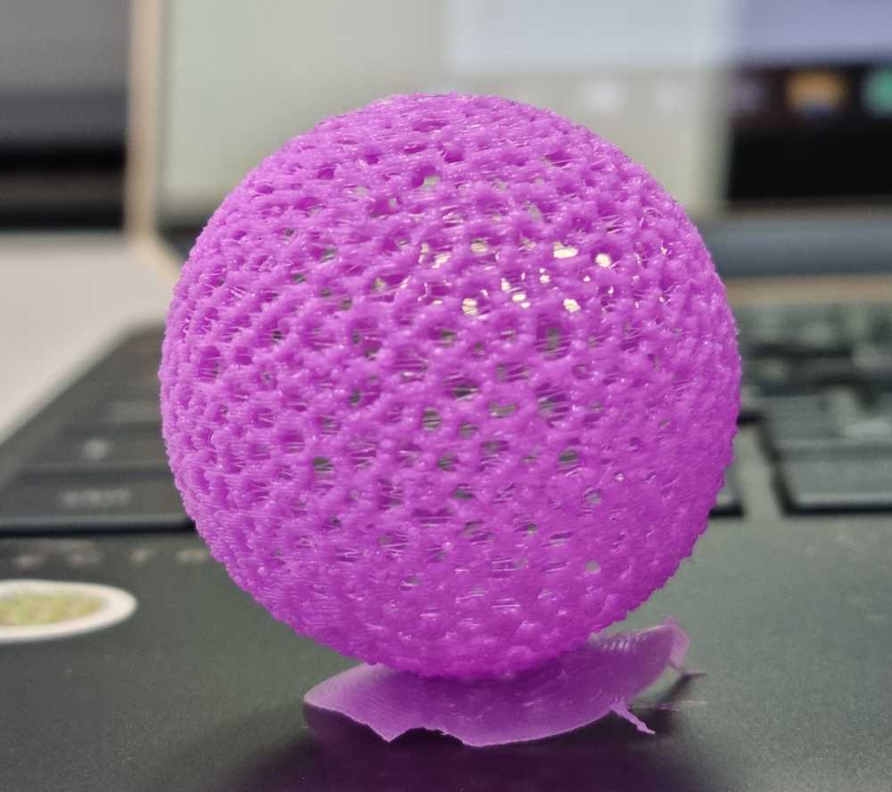 Voroni PLA sphere.
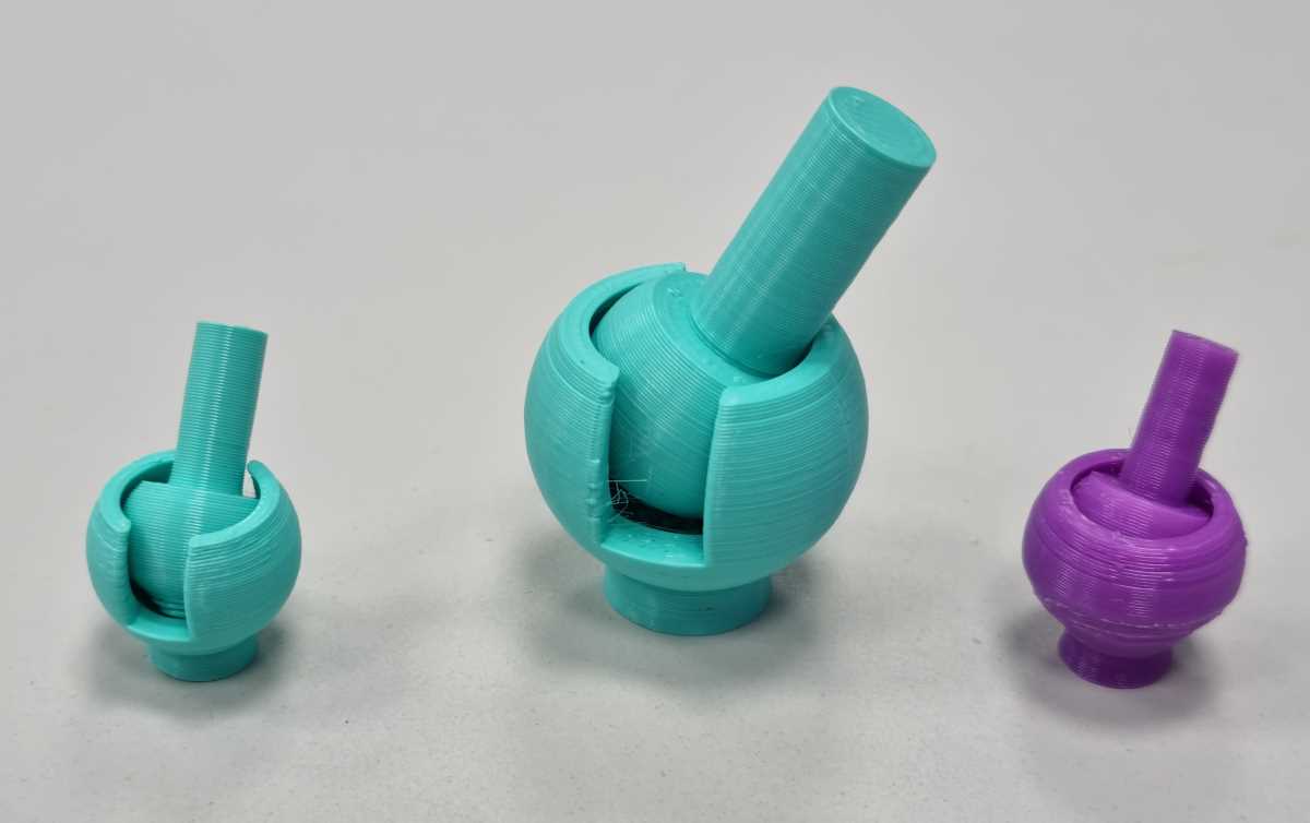
As we said before, we had a lot of machines and invested a lot of time printing, so I had time to skecth and create hinges in Fusion 360º. I´m not going to explain how I used fusion because we had a previous week for that. I also had problems with the width of the socket walls (I learnt by hard!), finally I was capable of printing it correctly with a minimum width of 0.6mm and a tolerance of 0.5mm. Here are some examples of what I practiced.
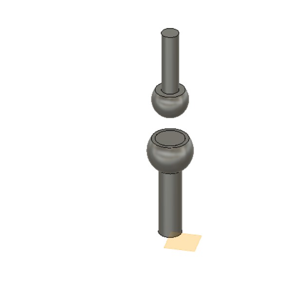 Fusion 360 design
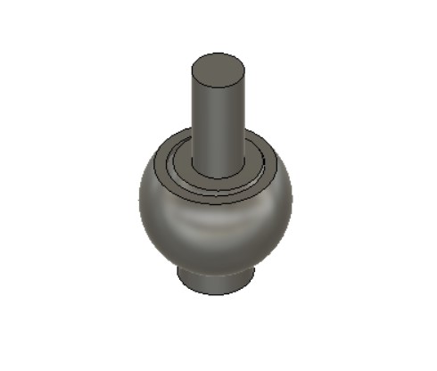 Ball and socket design
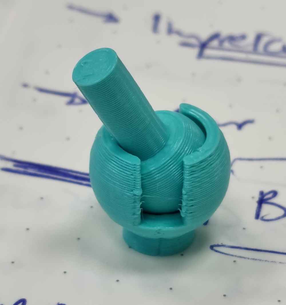 Ball and socket example
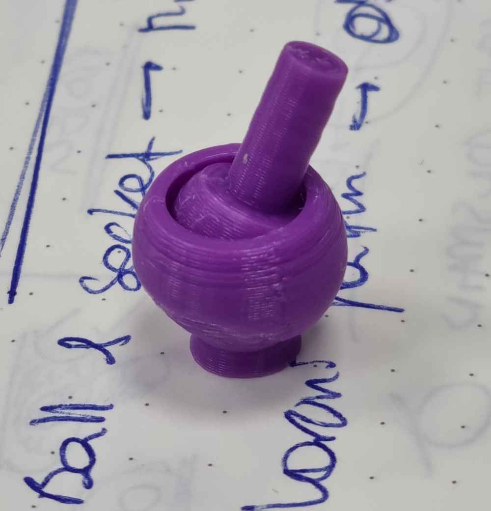 Second example.
VORONI SPHERE AND BALL AND SOCKET PRINTING SETTINGS
- Speed = 35 mm/s for the Vorony sphere and 50 for the Ball and socket.
- Support density = 15%.
- Printing Temperature = 205ºC.
- Build plate Temperature = 60ºC.
- Travel speed = 70mm/s.
- Retraction distance = 4 mm for the Voroni sphere and 5 mm for the Ball and socket.
- Retraction speed = 45 mm/s.
- Z hop = 0.08.
- Adhesion = brim for the Voroni sphere and Skirt for the Ball and socket.
Here you can download the .stl files: .stl files.
Here you can download the .f3d ball and socket Fusion 360 file: .f3d file.
3D SCANNER
In our FabLab, we have the Sense 3D portable scanner, which is actually not avaliable for sale. It´s a very very simple scanner to use, with a very simple software. You just have to plug it to your laptop, open the program, and just start scanning. It has two cameras, one for capturing the shape and size and the other one for color, capturing a 3D model image that you can edit from it´s own software which works with open source libraries in binary form.
You can check more details below:
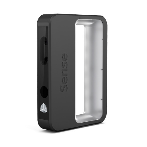
SENSE SCANNER FEATURES AND SPECIFICATIONS
- Minimun scan volume 0.2x0.2x0.2 m and maximum scan volume 2x2x2 m.
- Working distance = 0.2 - 1.6 meters.
- Field of view: 45º Horizontal, 57.5º Vertical and 69º Diagonal.
- Automatic object recognition.
- Class 1 certified laser.
- Operating temperature = 10 - 40ºC.
- 30 frame per second image stream via 2.0/3.0 USB to computer.
- Depth image size: 640(w) x 480(h) pixels.
- Color image size: 1920(w) x 1080(h) pixels.
And you can still download the software from here.
In order to scan with this 3D scanner software, I followed these indications:
| Position your object so that you can scan in 360º. |
| Make sure that the object is correctly detected by the scanner, you´ll see a green box in the screen. |
| Before modifying the pattern, we have to reduce the shape preserving: I changed the percentage to 90%. This will simplify the Voronoi pattern we´re going to make after. |
| Keep the scanner in it´s optimal distance range, wich is about 0.45 - 2 meter distance. |
| Reduce the shadows of your object as much as possible. |
| You can do as many passes of the object as needed, so try to fill in the gaps with new passes. |
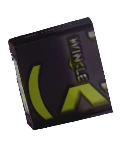 PLA box
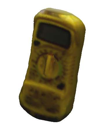 Multimeter
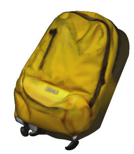 Backpack
At first, we started scanning my upper body, and it looked good, but we didn´t get the same results as we scanned smaller objects. You can soon see that it works better with bigger objects, with colours that are easy to differentiate, and with non-reflectable surfaces. Once you have your object scanned, you can edit it in the same progam and save it to a .stl file. Here below you can see some of the objects that we´ve scanned. As for first thoughts, don´t know why, but I expected better results, it´s quite fustrating when your trying to scan medium to small objects, but I guess it´s what this device is capable of. I need to try different scanners in the future.
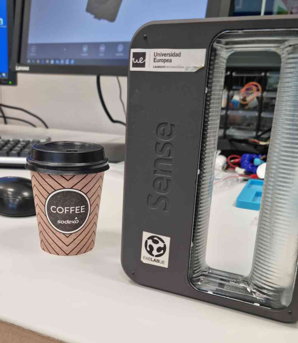 Scanning a cup
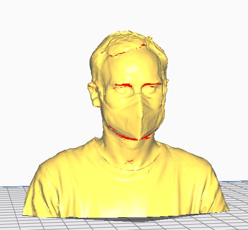 Myself