Week 4: Electronics Production

Group assignment: characterize the design rules for your in-house PCB production process
For this second group assignment, we have to characterize the design rules for our in-house PCB production process. In our FablabUE Madrid, we are going to use the Roland Modela MDX-40A.
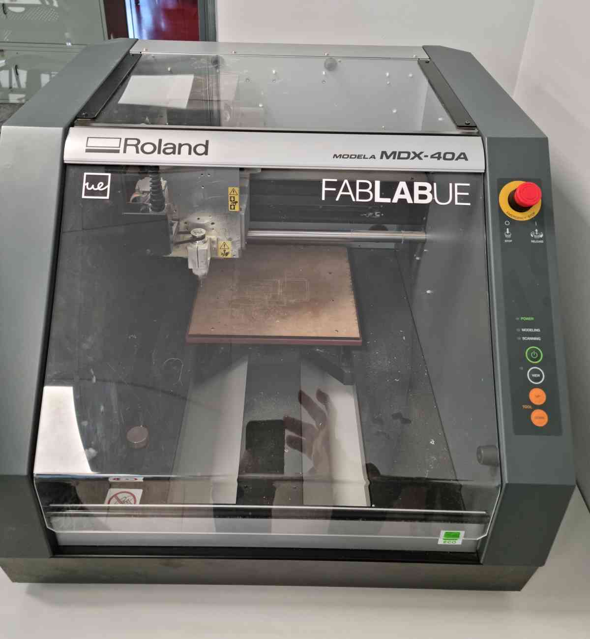
At this point of the academy we know that the best documenter of the three of us is our fabmate Pedro Chana (aka "Ken Follet"). Thank you, Pedro, for writing it, you are an amazing tech journalist! Here is the characterization of the machine.
Download the .rml files created: Fablab.UE Madrid traces .rmlor Fablab.UE Madrid outlines .rml
Individual assignment: make an in-circuit programmer that includes a microcontroller.
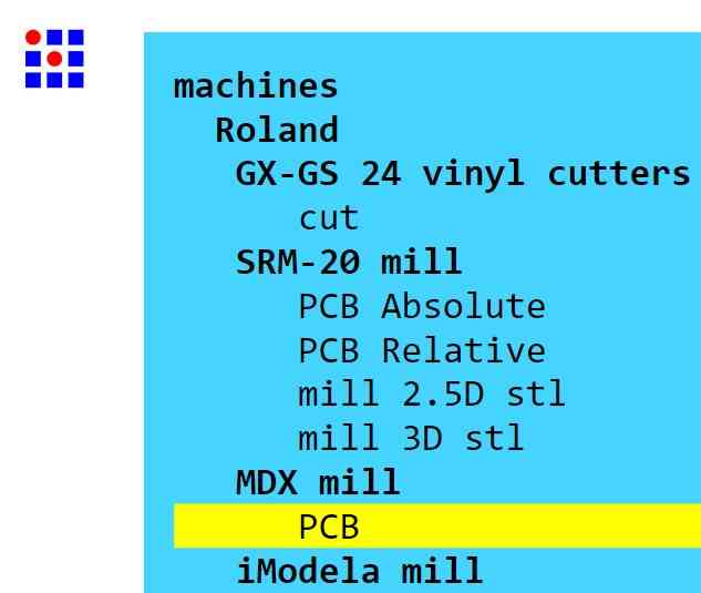
Program used: modsproject.org
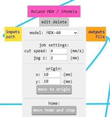
Program selected: Roland->MDX mill->PCB
Job settings: cut speed 4mm/s, jog z 2 mm
tool, cut depth, max depth and offset:
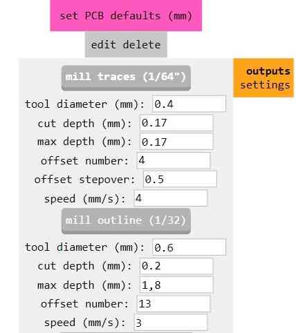
Traces tracepath:
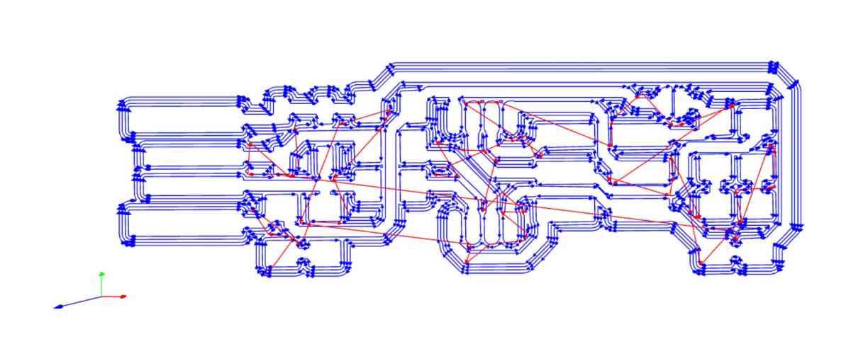
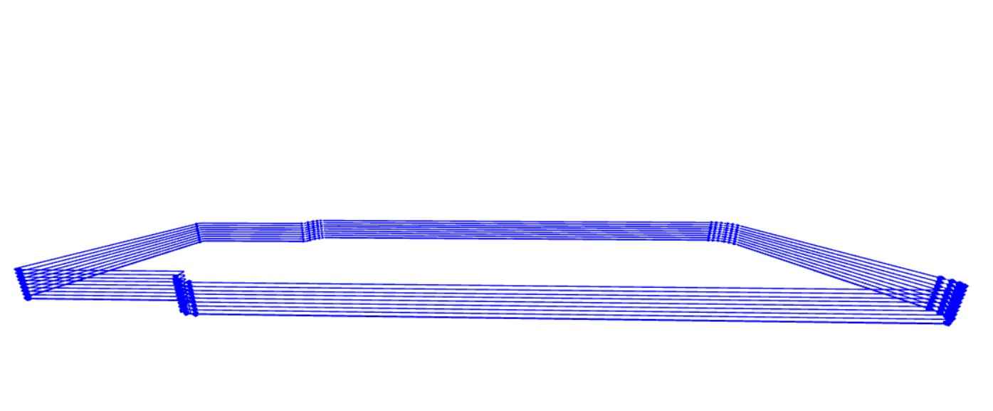
Outline tracepath:
After generating the rml file we uploaded it to the VPANEL tool (the one that controls the Roland machine)
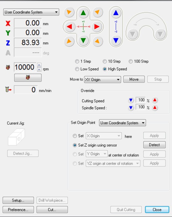
We changed the spindle speed to 15.000 rpm, Set X, Y origin and set Z origin using the probe. Clicking "Output" the Roland starts to mill.
As we told in the group assignment, we had three main errors starting with the Roland machine:
1-We didn't realize the origin was automatically set to x=10, y=10 in the machine software (VPanel).
2-The PCB FR1 was combed, so the circuit was undercut in some places and overcut in others:
3-We didn't know that when the machine cuts, it does it step by step in depth, so we gave it too much depth at first, breaking the best tip we had to do the work:
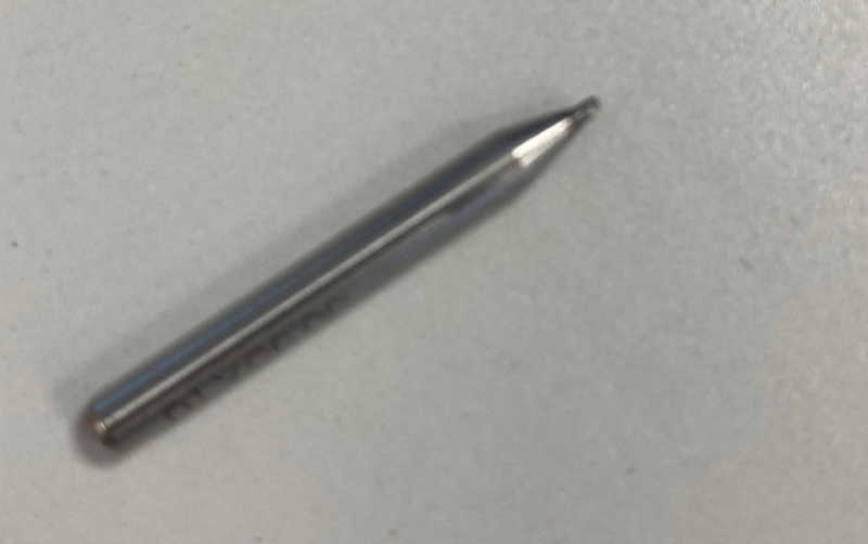
Broken tip
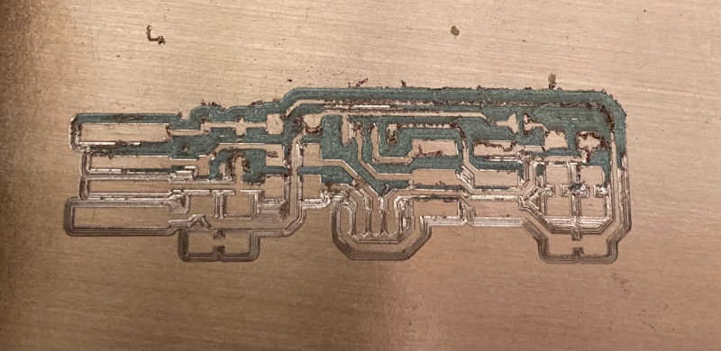
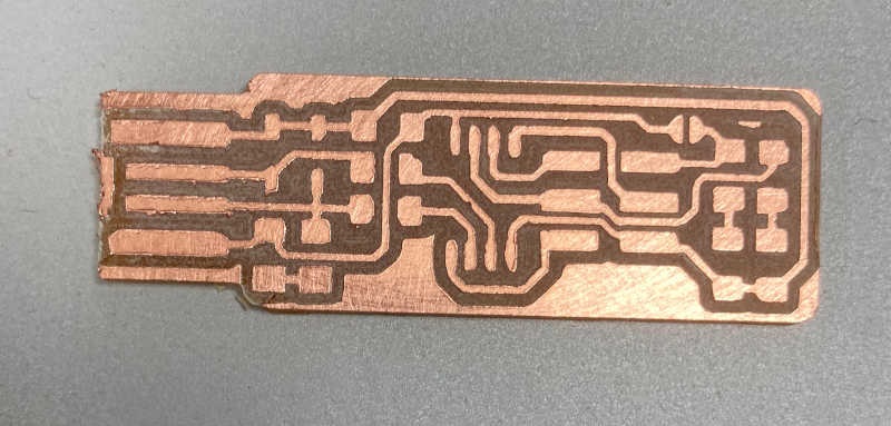
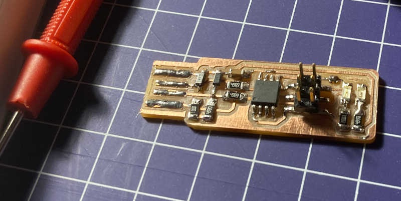
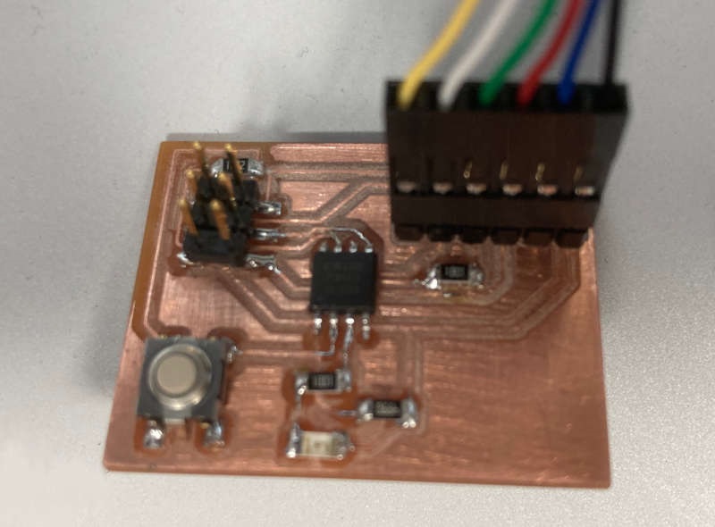
Finally, when we had the machine well adjusted, I cut my PCB, and after sanding a little bit It looked better than I thought:
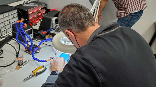
So, I began to solder the components to the PCB. As a telecommunications engineer I had some experience soldering components, but it was always through-hole soldering, not SMD soldering. So, the techniques are similar, but the scale is much smaller.
I checked this SDM soldering tutorial.
I also had a look at this interesting article. I copy here the main tips, because it can be very useful for other students:
Soldering tools and soldering tips
The soldering station is of course the most important part when soldering SMD components. It is important to choose a good tip. This is more important than a good soldering station because even good stations cannot be used properly with a wrong tip. When choosing the tip, it is important to take one that matches the size of the SMD components used. These components have a certain width of the pads and are therefore easier to solder with a tip that fits the size of the pads. Our advice is to choose a chisel-shaped between 1 and 2 mm. These are very suitable for heat transfer because of the shape. | 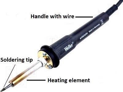 |
Soldering tin and flux
The choice of solder depends on your application, if you are going to perform repairs on existing electronics it is more convenient to take lead-free solder. This is because the solder present on printed circuit boards today is almost always lead-free for environmental reasons. Lead-containing and lead-free solder do not mix, and if you want to work with lead-containing solder, the pad will have to be cleaned completely.
If you want to build your own PCBs, you can use either lead-free or lead-containing, in which case only personal preference is important. It is also possible to use solder paste instead of tin, but this is almost exclusively used with reflow or hot air.
is essential to make soldering easy. By rubbing the pads of your print with flux, the solder will automatically flow to the right place. This makes it very easy to solder without soldering IC pins to each other.
Other useful tools
These tools are very useful, because SMD soldering with the fingers and the naked eye is a lot more difficult than with tools. For example, it is useful to use a third hand with magnifying glass, as you will quickly run out of hands when soldering. In addition, you will notice that the larger the magnification, the more stable your hands become. So it might also be an idea to create a loose magnifier or a to consider working properly. Furthermore, are indispensable to place smd components. To remove excess flux from the print, Isopropanol alcohol is a good option.
SMD soldering
The soldering process takes place in a number of steps that can follow each other quickly in practice. It is very important that the tip of the soldering iron is clean.
| 1. Tin one of the pads to make sure that the component can be placed. The pad should be fully tinned but be careful not to overdo it. | 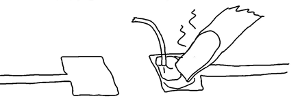 |
| 2. Place the component in the right place while keeping the solder liquid. A pair of tweezers is essential for this. It is important that the placement of the component is fairly good, otherwise the second pad will be difficult to get right. | 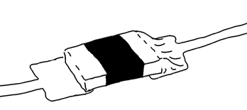 |
| 3. Lubricate some flux on the other pad. 4. Provide the tip with a good amount of solder. 5. Touch the pad with the tip, the solder will automatically flow into the pad and form a nice solder joint. | 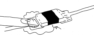 |
| 6. Inspect the solder connection and clean if it is cool, possibly the flux away with Isopropanol alcohol. This does not necessarily have to be done, but gives a more finished result. If there is too much solder on a joint, the easiest way to remove it is with a little desoldering tape. | 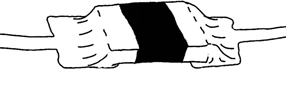 |
ICs soldering
These steps are very similar to the above, ICs are only a bit more difficult because they have a lot more connectors on a smaller area. This makes soldering a lot more precise.
| 1. Distribute flux over all pads. Tin one of the pads with a good amount of solder. | 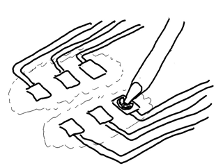 |
| 2. Place the IC in the right place while keeping the solder liquid. A pair of tweezers is essential for this. It is important that the placement of the component is fairly good, otherwise the other pads cannot be soldered properly. | 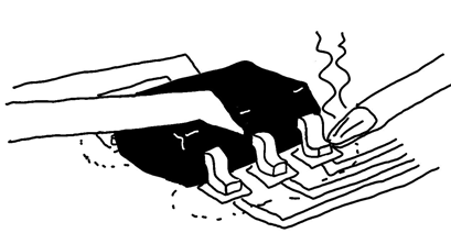 |
| 3. Solder the rest of the pads. The flow of the solder should be automatic, otherwise more solder should be added. Inspect the solder connection and clean it when it is cool if necessary the flux away with Isopropanol alcohol. This does not necessarily have to be done, but gives a more finished result. If there is too much solder on a joint it is easiest to remove with a little desoldering tape. | 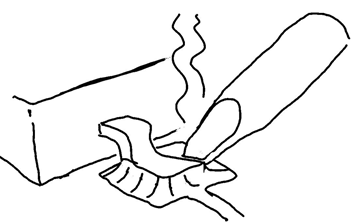 |
Soldering rules
| 1. Inside outwards. | The most convenient order to work is from the center of the board to the edges. For different component sizes, the easiest way to work is from small to large. |
| 2. Keep the pad cold. | If a path on a circuit board gets too hot, it is possible that it will let go. Then it is possible that the whole PCB can go away, if it was an important part. This can be done by simply not soldering for too long in one place. If it doesn't work out, try again later.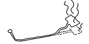 |
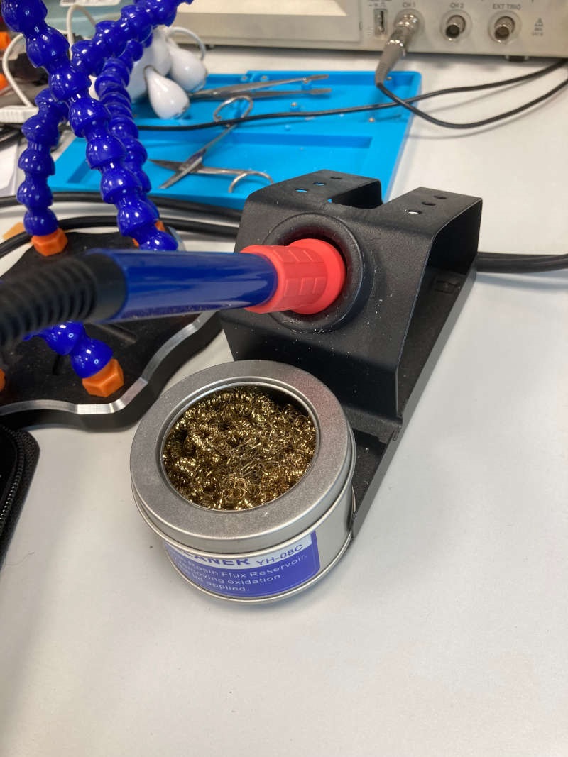
| 3. Keep the tip clean. | The soldering tip must be kept very clean when soldering with SMD. This promotes dissipation and heat dissipation. Oxidized soldering tin is a poor conductor, which also contaminates the soldering to be made. This is why the soldering tip must be cleaned for each series of soldering operations. The sponge must be moist, but not really wet. Otherwise the temperature of the tip will drop too much. |
Tools used:
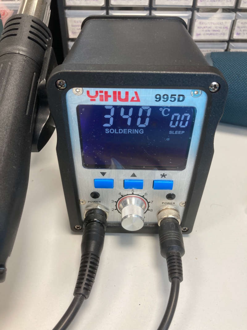
- Soldering station Yihua 995D, with hot air
- 0.5 mm lead-free solder
- Magnifying glass
- Third hand and vice
- Various tweezers
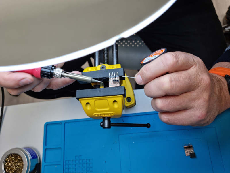
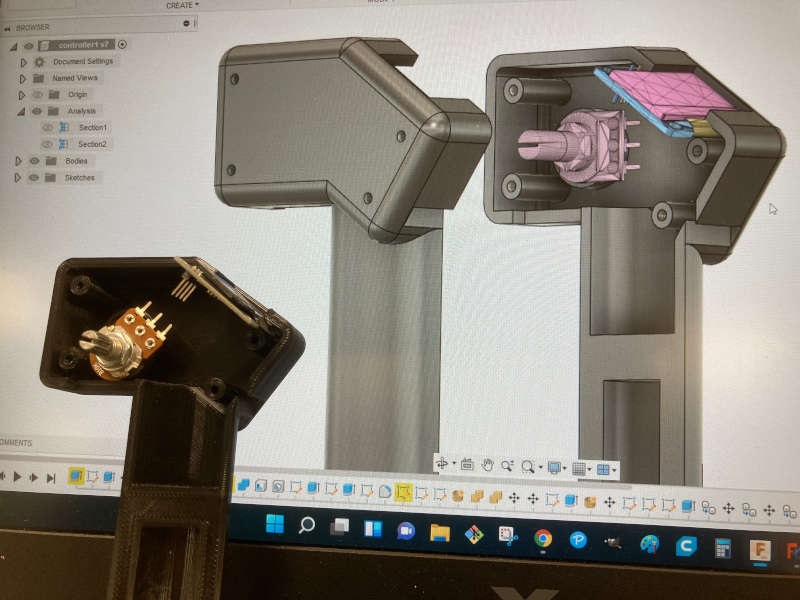
Connectors are one of the most critical parts in my case, as they support mechanical efforts after soldering that can move and break the soldering.
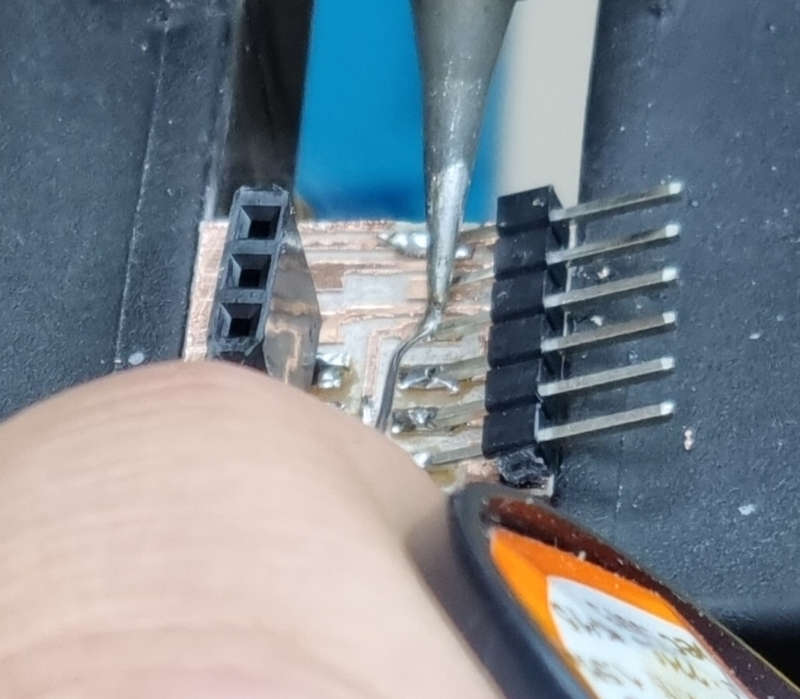
Removing the copper from the USB..
I didn't have too many problems, except for some difficult positions. And I have to say that I liked it a lot. As the solder is thinner, the process is quicker and the solder flows easily over the circuits and nodes.
Programming the programmer
What is a programmer?
The microcontrollers come empty from the chip factory. They don't have an internal software to run the instructions. We could say they come without "operating system". So we use another microcrontroller to install this basic software (or firmware) inside them.
Using the GNU AVR toolchain on Windows 10
What is the GNU AVR toolchain?
The AVR Toolchain is a collection of tools/libraries used to create applications for AVR microcontrollers. This collection includes compiler, assembler, linker and Standard C and math libraries. Most of these tools are based on efforts from GNU (www.gnu.org), and some are developed by Microchip.
A compiler is a program that converts high-level language to assembly language. An assembler then translates the assembly program into machine code (object). A linker tool is used to link all the parts of the program together for execution (executable machine code).
And what is an AVR microcontroller? AVR is an 8-bit microcontroller belonging to the family of Reduced Instruction Set Computer (RISC). In RISC architecture the instruction set of the computer are not only fewer in number but also simpler and faster in operation. The other type of categorization is CISC (Complex Instruction Set Computers).
To install the GNU AVR toolchain I follow the instructions of Brian's tutorial.
1-Install Git
I had git installed from week 1, so, point 1 done.
2-Install the Atmel GNU Toolchain
It's not easy to find the correct place to download it. I recommend to use the version found on the Github repository of Carlos Siles. It works perfectly. Done.
2-Install GNU Make
What is GNU Make?
GNU Make is a tool which controls the generation of executables and other non-source files of a program from the program's source files.
Make gets its knowledge of how to build your program from a file called the makefile, which lists each of the non-source files and how to compute it from other files. When you write a program, you should write a makefile for it, so that it is possible to use Make to build and install the program.
I downloaded and installed GNU Make from here:
3-Install avrdude
What is avrdude?
AVRDUDE is a utility to download/upload/manipulate the ROM and EEPROM contents of AVR microcontrollers using the in-system programming technique (ISP). It seems that the GNU AVR Toolchain includes avrdude.
I downloaded and installed avrdude from here: avrdude
4-Update the PATH variable
Path is a variable that Windows uses to locate the files you want to execute. So I have to update the path with the directories where the executable files of the recent instalation are.
- C:\Program Files\avr8-gnu-toolchain\bin
- C:\Program Files (x86)\GnuWin32\bin
- C:\Program Files\avrdude
To update the path you have to go to the Control Panel, look for "variables", and click "Environment Variables".
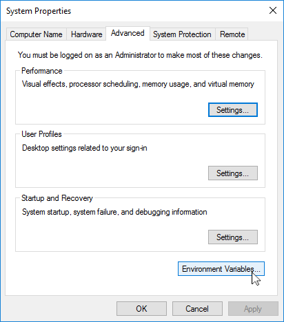
Then double-click on Path, and click "New" to introduce the new directory.
5-Install drivers for your programmer
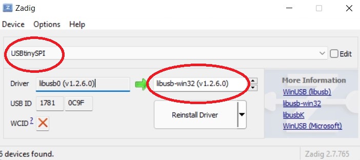
Your Operating System has to recognize your FabISP programmer(based on ATTiny) when you connect it to the USB port. So you need the proper driver to do it. To install the drivers the best option is to us Zadig, a USB drivers installer for Windows. You can download Zadig from here: https://zadig.akeo.ie/
Note: Insert your FabISP programmer before launching Zadig. If you don't do it, the driver for the USBtinySPI won't appear to be installed.
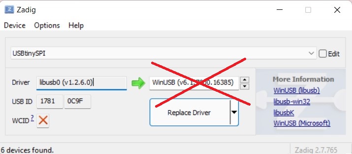
It's also very important to install the drivers in libusb-win32, not in WinUSB.
This is OK:
This is not OK:
6-Sanity check
Go to Git Bash. It's important to run everything on git bash. Don't do it on the Windows terminal. I won't work.
make
I type make -v and after enter I see:
GNU Make 3.81
Copyright (C) 2006 Free Software Foundation, Inc.
avr-gcc
I type avr-gcc --version and I see:
avr-gcc.exe (AVR_8_bit_GNU_Toolchain_3.5.4_1709) 4.9.2
avrdude
I connect my programmer to a USB port and type: avrdude -c usbtiny -p t45 and I see:
avrdude.exe: Error: Could not find USBtiny device (0x1781/0xc9f)
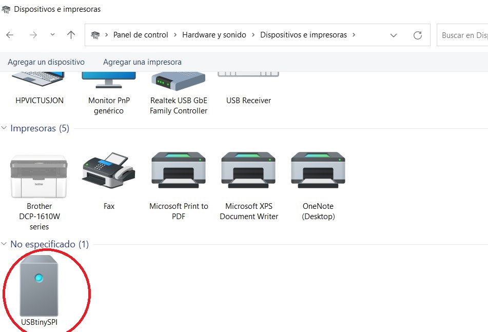
My mistake was that I had install my drivers on WinuUSB, not on LibUSB. I Install the drivers again and.. voilá, my device is recognized. You also can see it on the Windows System Information (Devices and printers)
Let's program the programmer
First, some concepts to clear myself up: Our ATtiny is still without firmware. So, it doesn't know how to deal with USB connections. If you connect it to the USB port of your computer the led is going to flash, because it's receiving power from the USB port. But your computer is going to complain because it doesn't recognize the device. On the other hand, if you connect the programmer to the computer, Windows will recognize the device as USBtinySPI. So, it´s better to connect the programmer to the computer and the new ATtiny just to a Power supply USB connector. So you are not mistaken by the USB error messages.
I run make flash and everything seems to be ok. So, I wrote on the memory of my ATTiny for the first time!
After that I run make fuses and again is working.
After that I took my programmer off the USB port and put the ATTiny on it. I checked that it was recognized by Windows as a USBtinySPI. How proud I am! My little child knows how to speak!
I connected the programmer again to the computer USB port and the ATTiny to the USB power supply and run the final make rstdisbl.
Finally I broke the bridge Vcc - Vprog on the PCB, and my FabISP is ready to be tested.
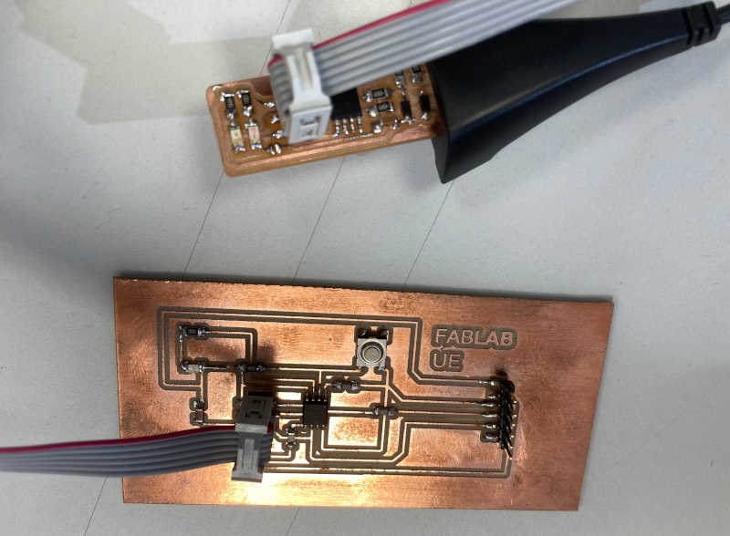
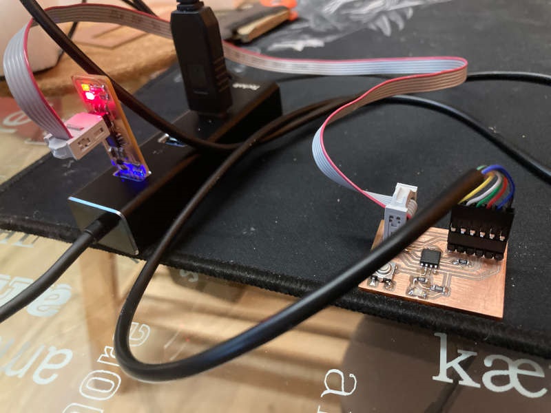
Programmer tester
My instructor gave me another "empty" ATTiny board to test my programmer. So, I connected the board to my brand new programmer and tested it with a make flash instruction, just to try.
$ make flashavrdude -p attiny45 -c usbtiny -P usb -e \ -U flash:w:fts_firmware.hexavrdude: AVR device initialized and ready to accept instructionsReading | ################################################## | 100% 0.00savrdude: Device signature = 0x1e9206avrdude: erasing chipavrdude: reading input file "fts_firmware.hex"avrdude: input file fts_firmware.hex auto detected as Intel Hexavrdude: writing flash (2470 bytes):Writing | ################################################## | 100% 2.52savrdude: 2470 bytes of flash writtenavrdude: verifying flash memory against fts_firmware.hex:avrdude: load data flash data from input file fts_firmware.hex:avrdude: input file fts_firmware.hex auto detected as Intel Hexavrdude: input file fts_firmware.hex contains 2470 bytesavrdude: reading on-chip flash data:Reading | ################################################## | 100% 2.32savrdude: verifying ...avrdude: 2470 bytes of flash verifiedavrdude done. Thank you.
Everything seems to be ok and working.
Finally, I sent a simple program to switch on a led using Arduino IDE:
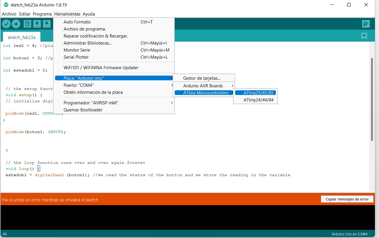
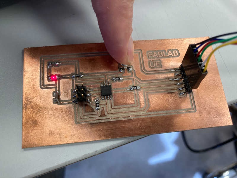
The program works in the new board, so my programmer is correctly working.