Week 7: Computer Controlled Machining

Group assignment
- Do your lab's safety training
- Test runout, alignment, fixturing, speeds, feeds, materials, and toolpaths for your machine
I completed the group assignment with my fabmate, Pedro Chana. In addition to the testing, I have to say how important it is to work in group, or pairs, as it is our case. Lots of times one of us realizes of something that the other one didn't. We do a lot of peering review, re-checking the parameters, and making sure that everything is ok before starting the machines. Thank you, Pedro, for being so great partner.
Individual assignment
- Make (design+mill+assemble) something big (~meter-scale)
I'm trying to make myself as much as pieces of my final project as possible. So, as my final project is an electric ski, I thought it was a good idea to CNC machine the blades.
I spent some time watching Youtube videos about ski making. The technique is to make a "sandwich" composed of the base, a layer of fiberglass, the wood core, another fiberglass layer and a top (optional). The fiberglass can be substituted by carbon fiber or titanal layers.
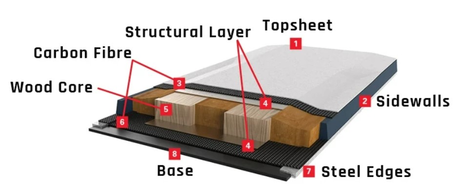
All this layers are bond together using epoxy resin and placed into a press to glue it and make the profile shape of the ski.
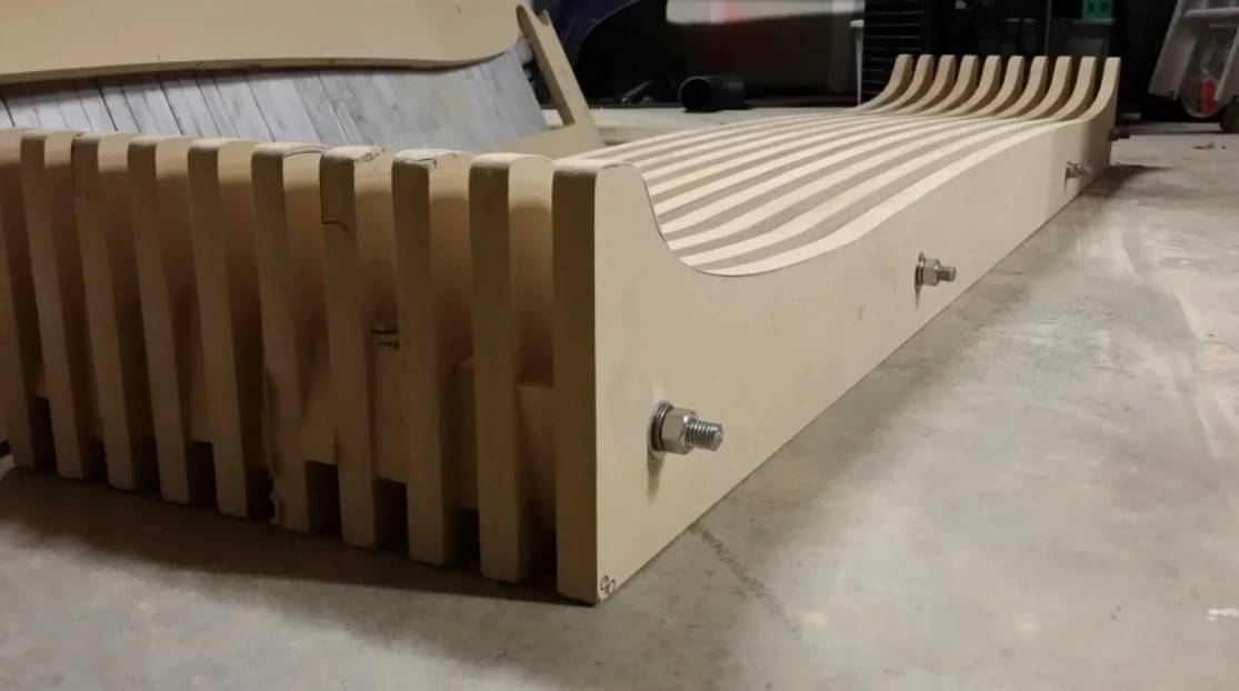
Image: ski press from instructables.com.
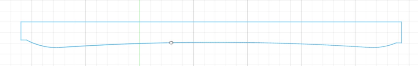
So my plan is to CNC mill the press first, and after that make the wood ski core also with CNC machining. I used the SnoCAD program to get the shape and profile of the ski. I chose an standard 170 cm ski to make mine.
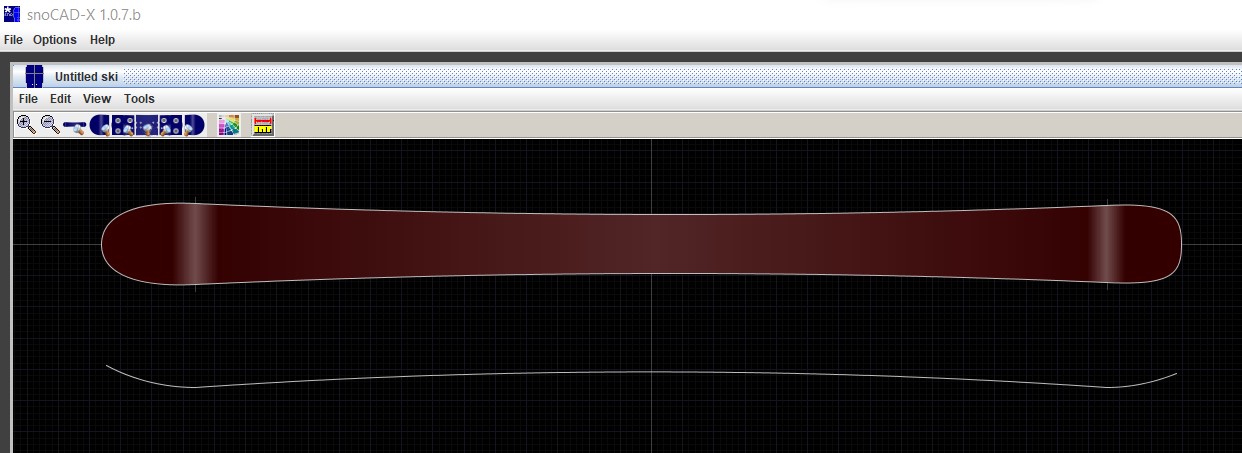
I exported it to DXF to get my model. The DXF file is here.
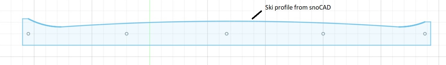
After that I uploaded it to Fusion360. The problem was that Fusion360 was very slow working with the shape. I suspected it could be because of the high number of points created for the curves. So I changed it in Fusion360 and modeled it as splin curves. After that I use the ski profile to model the top of the press:
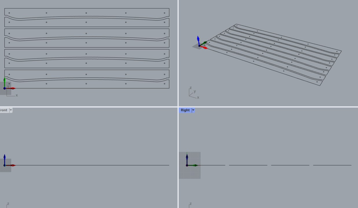
I estimated I needed 11 elements like those to make the press, so it was time to nest them onto the piece of wood. I used the Deepnest program, but I wasn't able to get any result of it. So I decided to nest it myself, because the shapes were quite easy to place.
First I tried to reuse the lines, in the way that a line could be the edge of 2 adjacent pieces. But my instructor Alberto advised me not to do it, so I placed the pieces so they are completely independent:
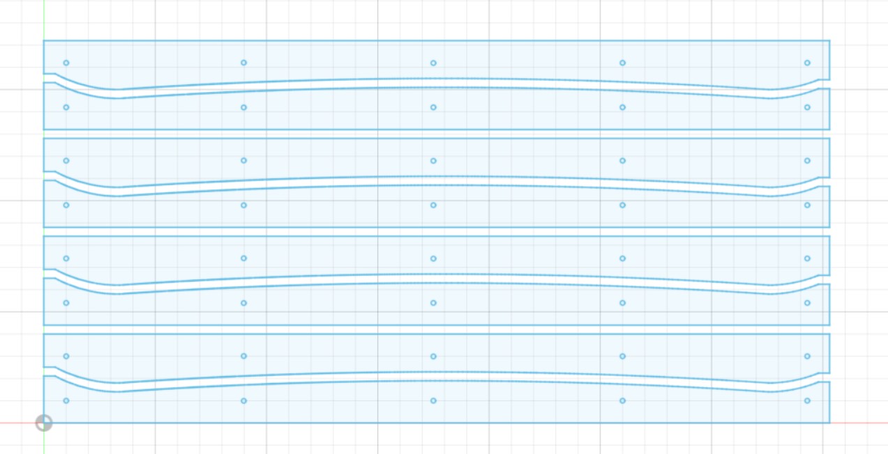
You can download the DXF file here.
My instructor suggested that instead of routing the holes it would be better and faster to use a 10 mm wood drill to make them at once. I had to configure the CNC machine to engrave instead of profile. And of course I had to change the drill and mill between jobs.
CAM process
First I loaded the .dxf file on RhinoCAM
Then I set up the material (a box). In our Fablab the rule is to put the origin on the left low corner of the material, and just on the surface of it.
After that I moved the model to the origin, adjusting it to the material.
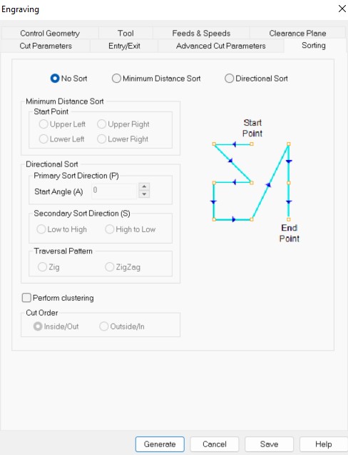
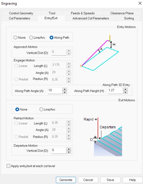
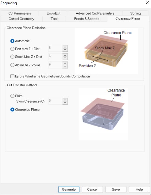
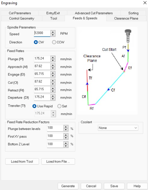
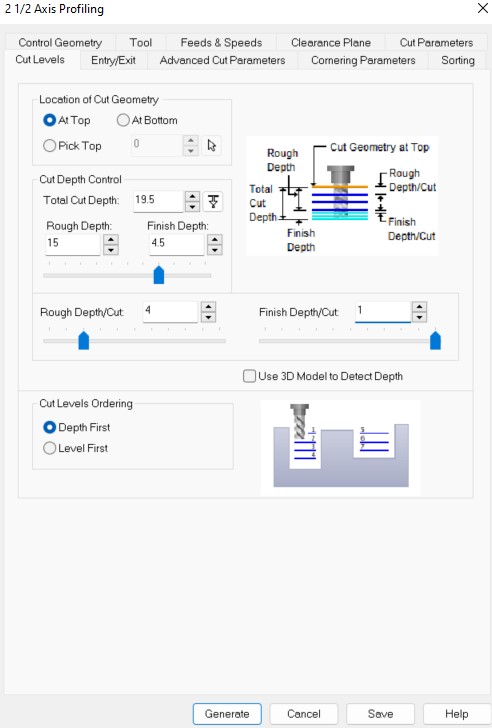
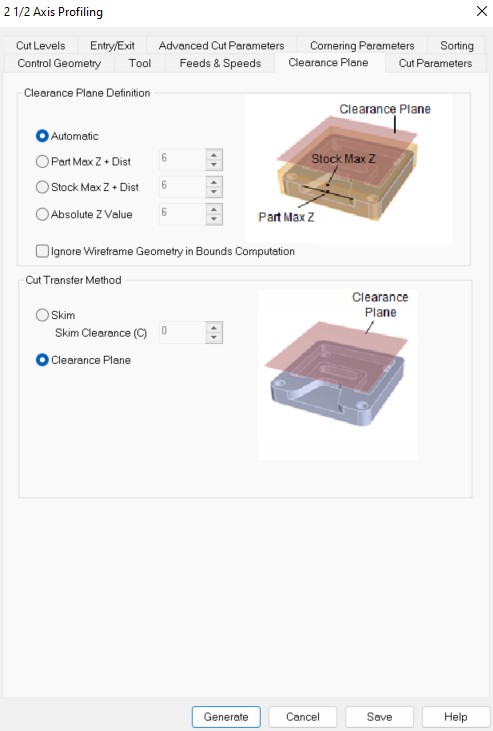
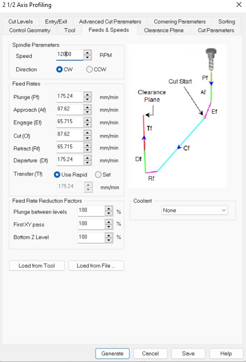
There are a lot of parameters on the CAM process, so it's important to check them before machining.
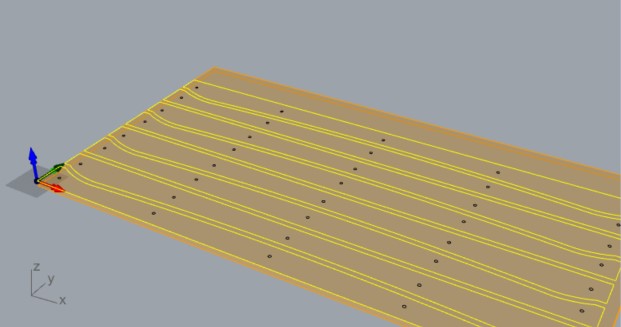
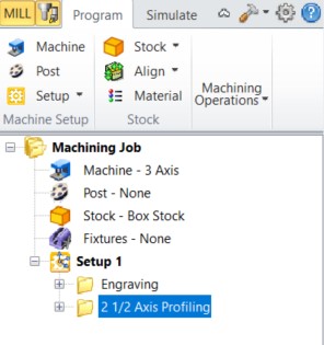
First the machining job. I will use engraving to make the holes (with a drill) and profiling to make the press pieces external cutting.
Selecting the holes:
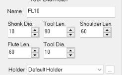
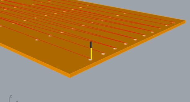
Then I selected a 10 mm tool
And about cut levels, as I'm using a drill, I can cut directly a depth equal to the total thickness of the board (19mm)
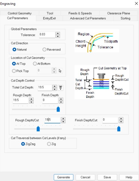
Other parameters:

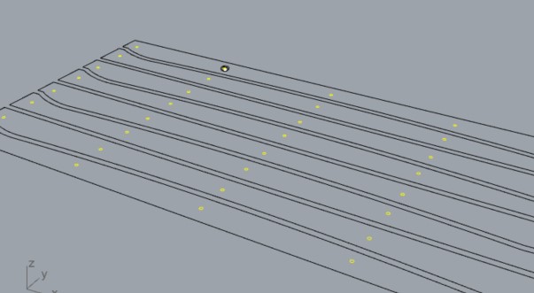
Then I generated the job
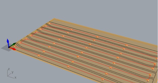
And simulated it (this step is essential to guarantee a good job)
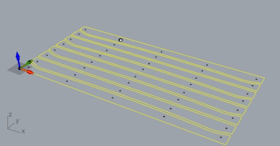
For the outline I added a profiling job with a 6 mm mill:
I selected the lines:
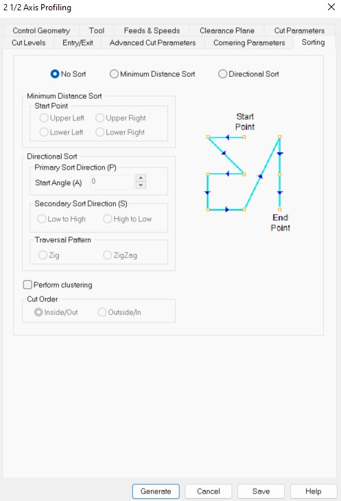
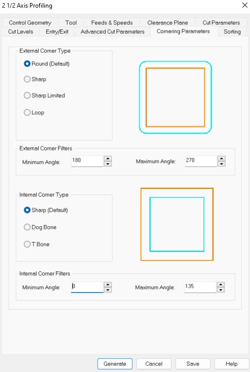
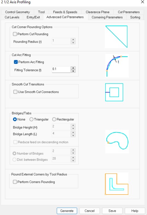
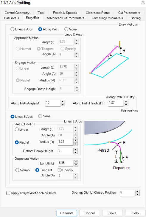
Then I set up the rest of the parameters:
After using RhinoCAM I generated the file for the CNC machine. But when I uploaded the file there was an error "Could not perform arc generation". I suspected it was again because of the curves, perhaps too many spline arcs there. So I drew the curves as small straight lines. At a big scale you can't see the difference. I loaded the file into the CNC machine and without problems this time.
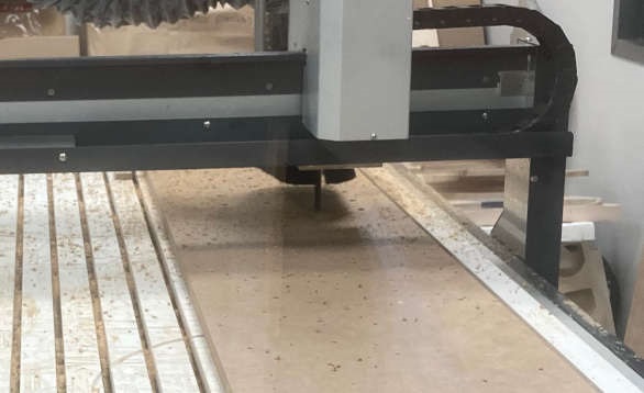
I fixed the board to the machine, set xy origin and set z origin using the probe. After that I launched the job.
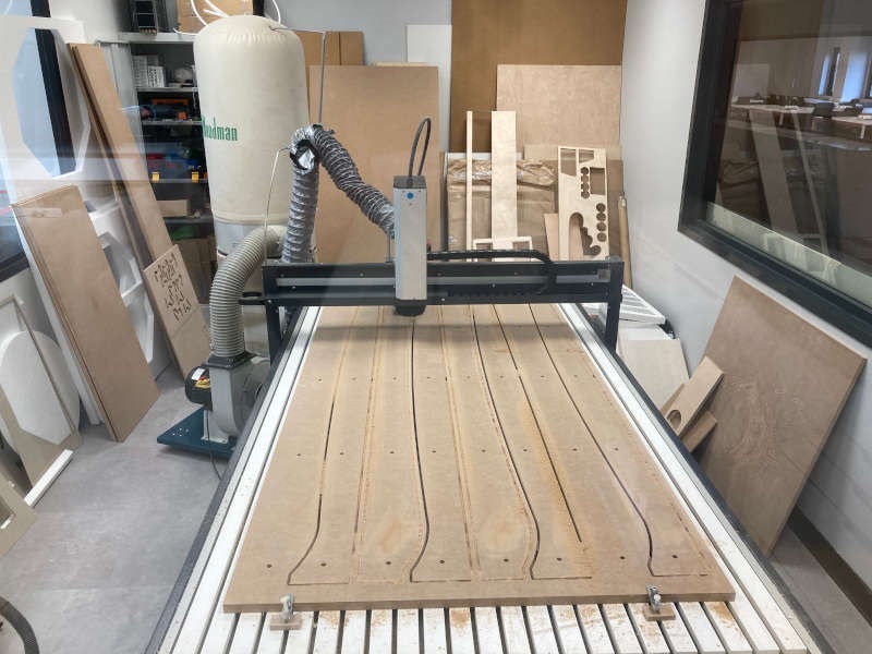
I needed at least 11 pairs of press pieces, so I had to cut three boards like that. We had to pre-cut the boards and bringing them from the downstairs workshop. Then I discovered that MDF is made of lead...
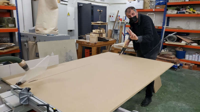
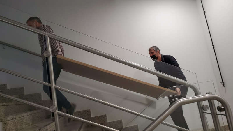
Images: digital work at the lab
Next day I cut another 2 boards. They were made with the same files and parameters, but in one of them the cut was less deep. Perhaps because the Z-axis adjustment can differ, depending on where the probe is placed and some tolerance of the tool.
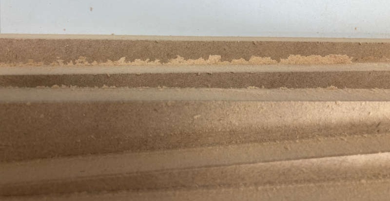
A less deep cut leaves some rough edges
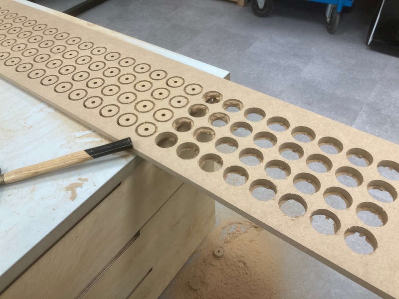
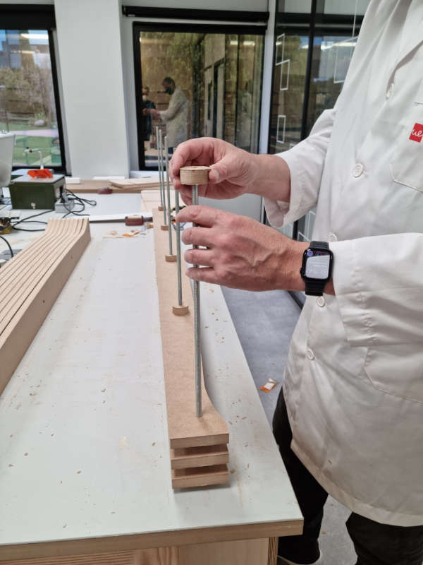
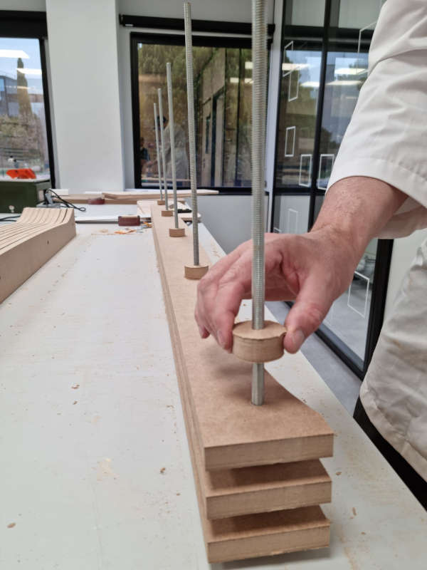
To separate the different slices of the press I want to use wood circles with a hole in the middle (at least 100 of them). So next step is to cut the circles. I modeled them on Fusion 360.
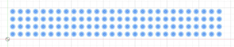
You can download the DXF file here.
Applying the same technique I used before (engraving for the holes and profiling for the circles) everything seemed to be ok. However, I had some problems with the Z-axis probe (the cable fails sometimes), so at certain moment I lost the x-y calibration (I think it was because I had to push the safety button of the machine). The result was that the circles and the holes weren't aligned.
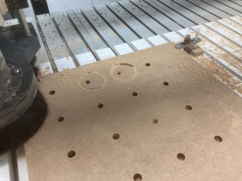
I won't forget it: If you push the safety button you loose the zeros of the machine.
It was very difficult to recover the original alignment, so I had to use another piece of wood. This time everything worked as expected.
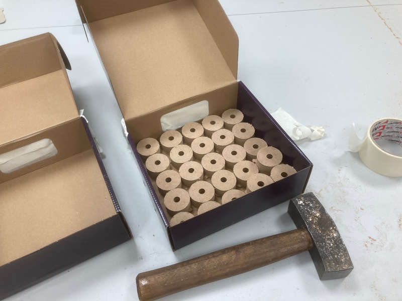
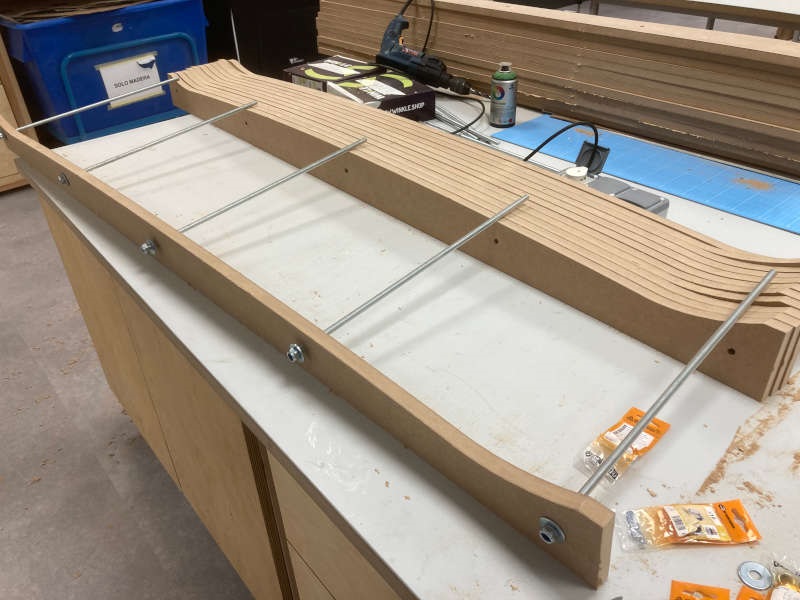
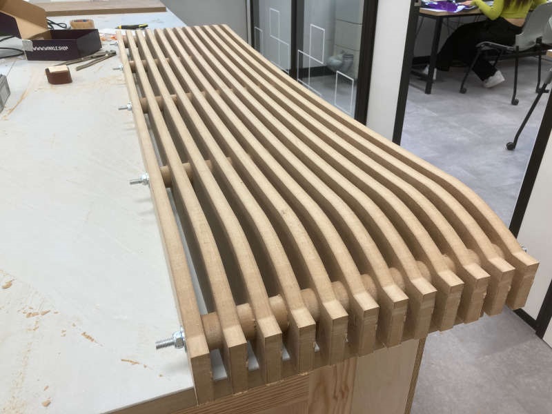
It's time to make the ski press. I used some threaded rods and nuts to join it.
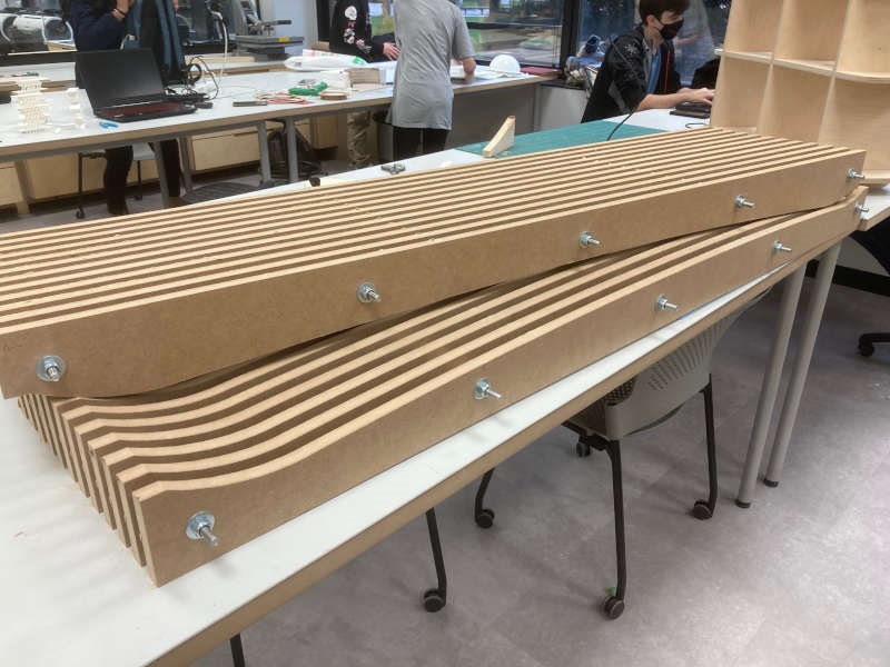
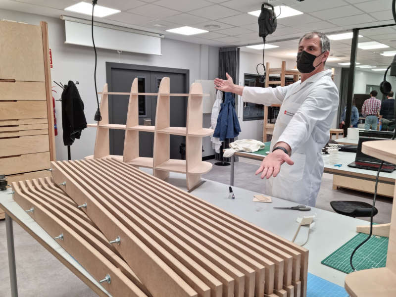
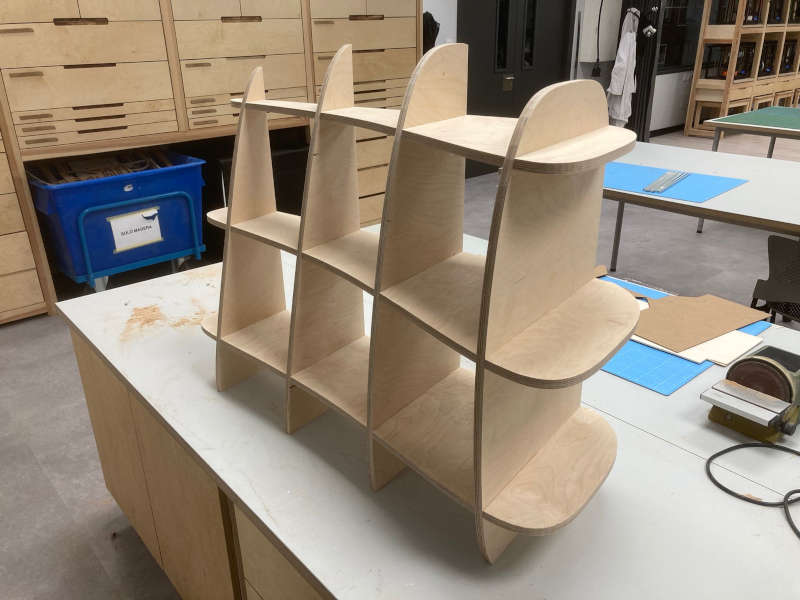
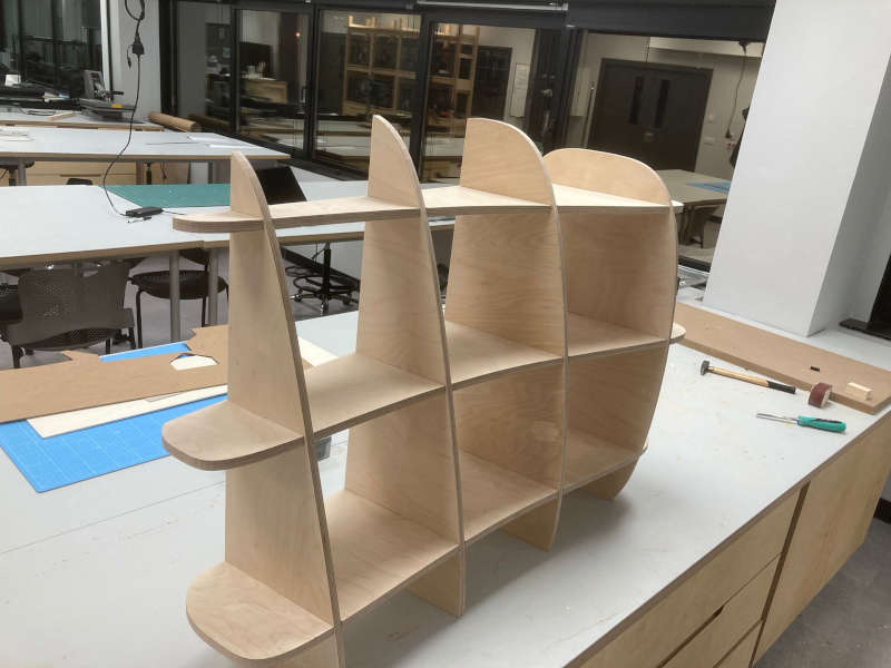
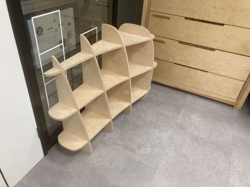
The shelves
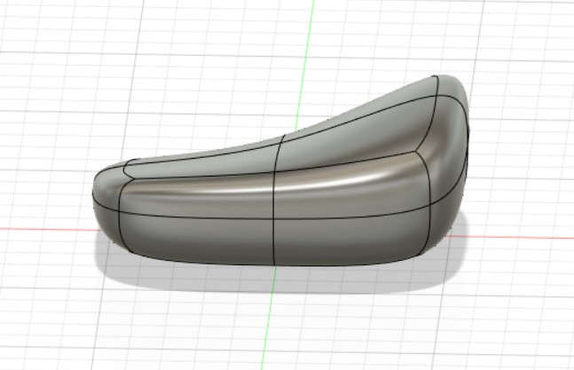
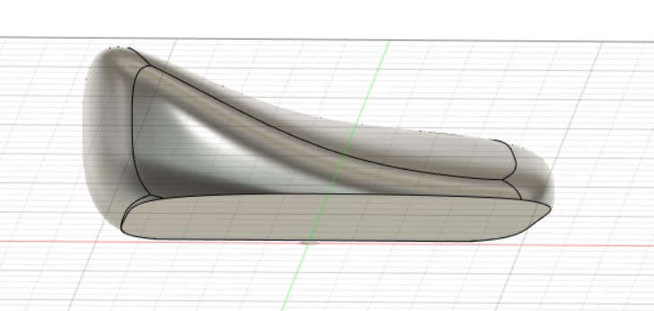
Apart from the ski and ski press, I was very interested in the curvy forms made slicing 3D volumes. I planned to make some curvy shelves for my "home mini-fablab". First, I created a generic volume in Fusion360 and changed it moving the faces until it was the shape I was looking for:
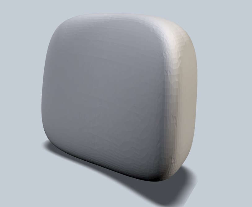
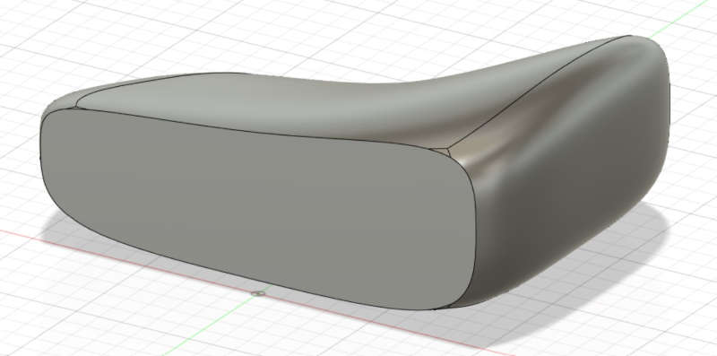
Later I cut the bottom and the back of the volume, so it's flat to adjust to the floor and the wall:
The Fusion 360 file is here.
After that I uploaded it to the Slicer for Fusion360 and got the pieces with the option of "Interlocked Slices", 4 slices on the x axis and 3 slices on the y axis.
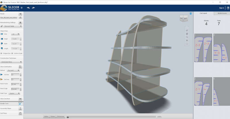
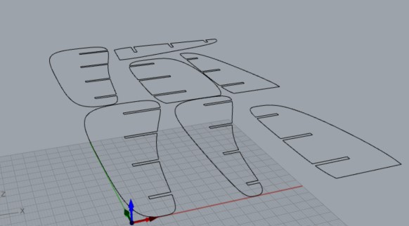
Clicking "get plans" and Slicers generates a .dxf file that goes to the CNC machine...
The dxf files are here.
I loaded the files onto the RhinoCAM software:
I setup the stock (box)
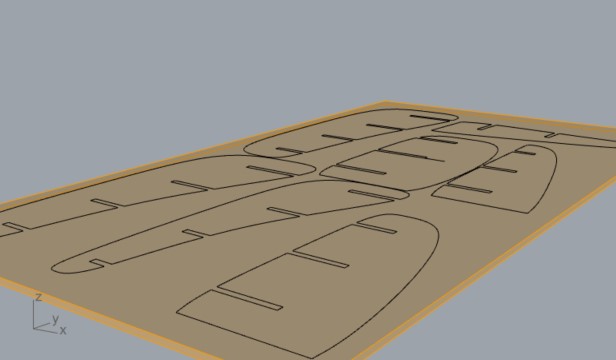
And I used a profiling job with the following parameters:
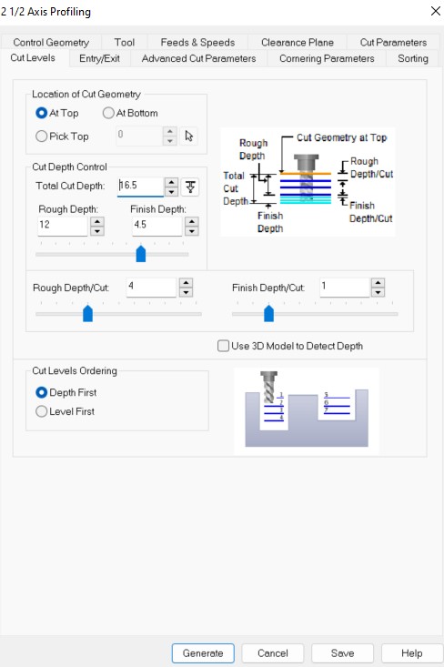
Parameters are similar to the one used to profile the press, except for the levels, adapted to 16 mm thickness.
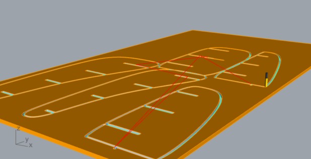
I launched the job in RhinoCAM:
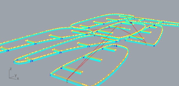
And simulated it:
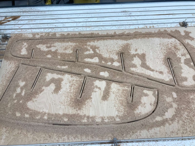
After checking everything is OK I went to the CNC machine.
And finally the hero shot with both creations: