WEEK 07: COMPUTER CONTROLLED MACHINING
For this fifth group assigment, my "fabmate" Jon Merino and I, plan our time management for the following achievements:
- CNC Machine description.
- Preparation of our test design settings: alignments, speeds, feeds, toolpaths, etc.
- Safety training.
- Test run: CNC hands on.
- For the INDIVIDUAL ASSIGNMENT , my planning will be:
- Design something big (meter scale).
- Mill and assemble it.
GROUP ASSIGNMENT
1. CNC MACHINE DESCRIPTION
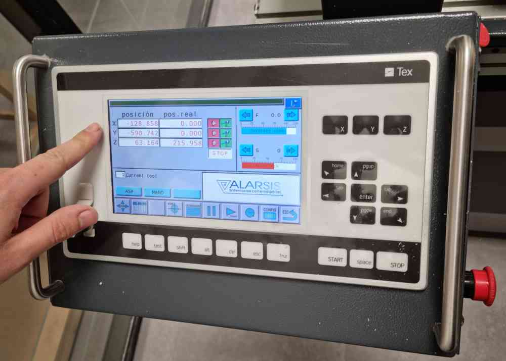
Here, on the Fablab.UE Madrid, we have a Alarsis FR210 milling machine:
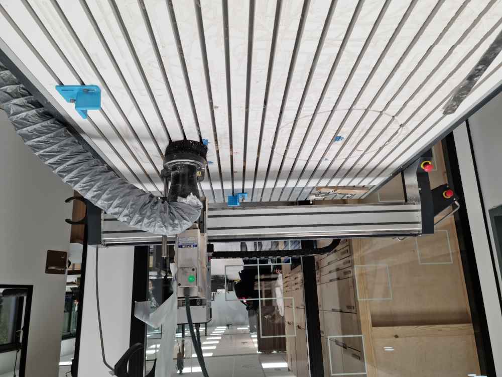
The FR210 milling machine is produced by a spanish company named Alarsis, which designs and manufactures cutting systems since 2005, such as CNC milling machines, hot wire foam cutters, plasma tables, laser, etc., all under their own R+D+i, with the following technical specifications:
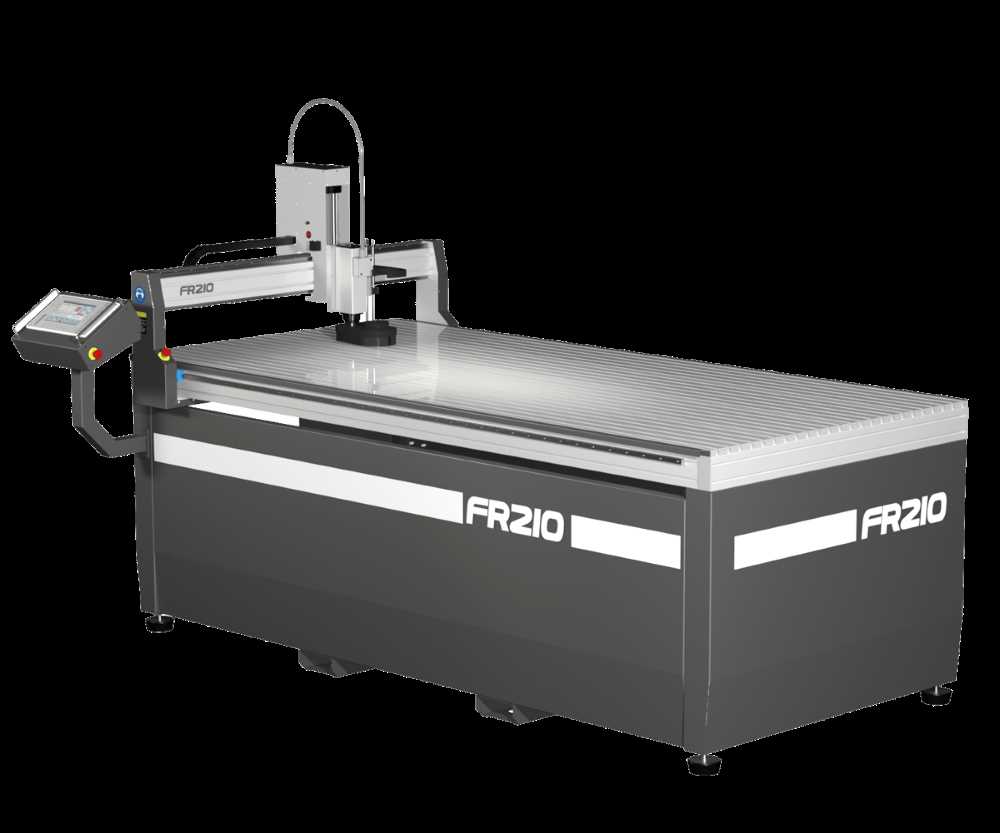
- Travel speed 40 meters/min.
- Resolution 0.02mm.
- Chip suction system.
- Head with Kress 1050w or ELTE brushless 1.5 CV motor as an option.
- Probe for Z axis zero setting.
- Useful working dimensions 2000x 1000 mm.
- Useful bridge height Z 120mm.
- Machine dimensions 2400 x 1150 mm.
We have a lot of respect for this weeks assignment so, we initially invested a lot of time in understanding how everything works, the principles that are behind it and the parameters that we need to set. As we don´t have any experience with CNC milling Alberto, our instructor, gave us all the information needed regarding CNC characteristics, tools, software to use, safety and CNC handling. We are fortunate to be two students, it allows us to support and supervise each other constantly and in weeks like this, it gives us an extra confidence and security that everything is going to be double-checked.
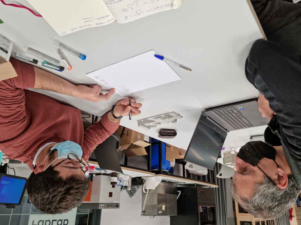 Reviewing CNC milling concepts
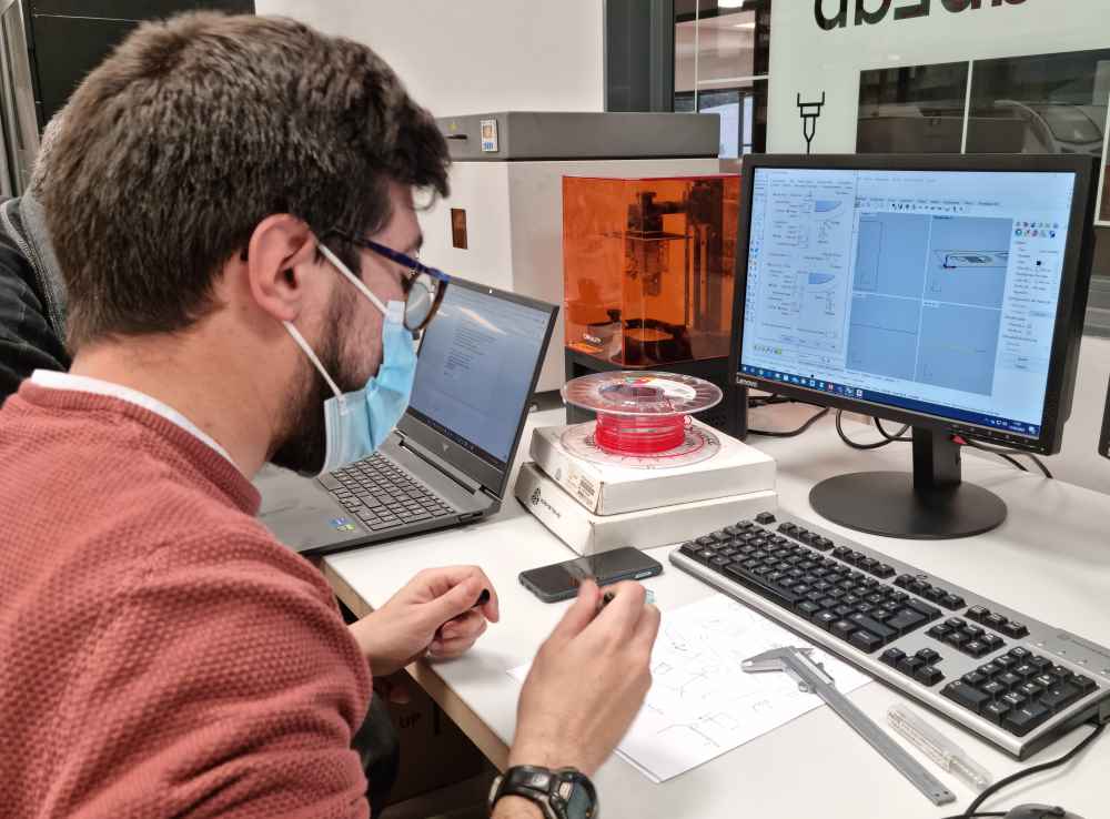 Programing dxf files with RhinoCAM
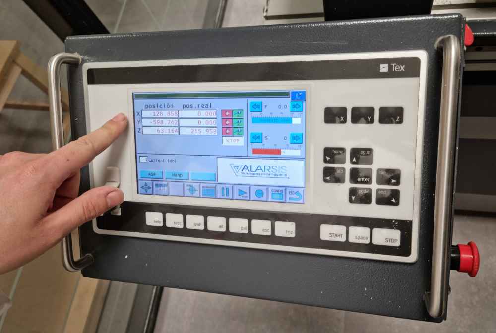 Getting to know our CNC
2. PREPARING SETTINGS FOR THE TEST RUN
In order to practice, managing the settings of our CNC, and getting our first hands-on experience, we ran a test run in a small design. We used RhinoCAM plug-in software because it´s the program used in our fablab, due to the fact that it´s the program that university students use, so it´s a way to protocolize the process. Regarding the process itself, we can divide it into 3 parts before we can export our final file to our CNC: First set our material dimensions, measurements and positioning, second set all the machining operations (mill routing), and third, and most important, simulate and check the toolpath view. Here you can check the steps we made:
FIRST: MATERIAL DIMENSIONS, MEASUREMENTS AND POSITIONING. It´s very important to dimension and position your material and design properly so we won´t have any problems during the milling. We had to practice a lot of times, with different files, to practice and really understand all the setting from this first step.
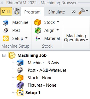
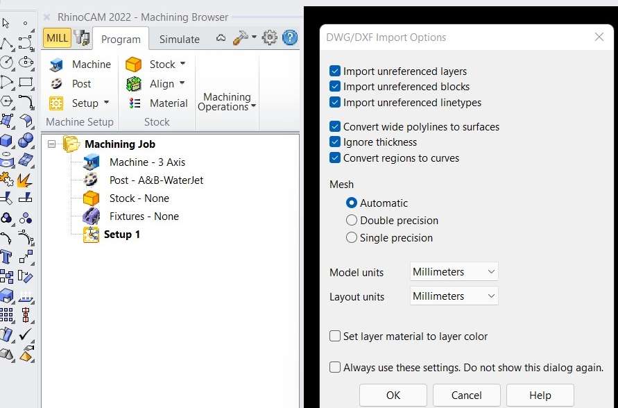
| Open RhinoCAM plug-in in Rhino software. upload your dxf design. In our case we designed a small square (50x50mm) in fusion 360. |
| Make sure that we are in the MILL module. If not, we won´t be able to give our box stock dimensions. |
| Introduce the material positioning: Select all of your design (it will change to yellow), type move in the command bar, select to move from the desired point, in our case from the bottom left corner, indicate that the position is 0 an press intro. |
| It´s recommended to leave a security margen so you don´t hit the clamps: Move position to (30,30,0). |
| Go to STOCK -> Box stock to add the material you want to cut dimensions: Also add the corner coordinates (Xc0,Yc0,Zc=material thickness in negative values!). |
| Once our material is correctly dimensioned and positioned it´s time to set the machining operations |
 Opening files.
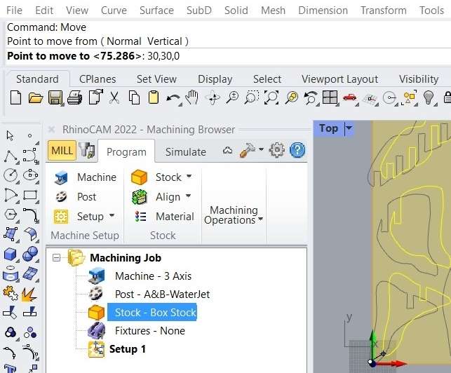 Material positioning.
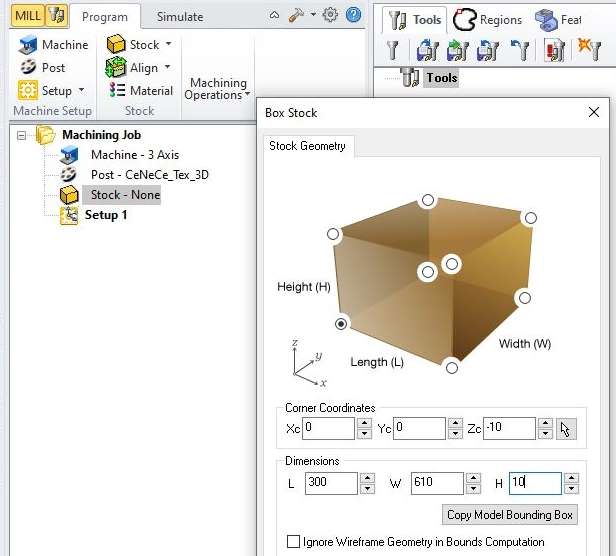 Box stock.
SECOND: SETTING THE MACHINING OPERATIONS. For this second step, we checked both Alberto González and Lorena Delgado repositories due to the fact that they used the same CNC as we are. So, that helped us with the cut speed calculating and the initial test run settings. It´s important to remember that once we´re setting all the machining parameters we don´t have to press generate after changing each one of them. We´ll just generate a simulation without all the parameters set, and a second machining job setup that will confuse us. To avoid that, we can leave the tool setting until the end.
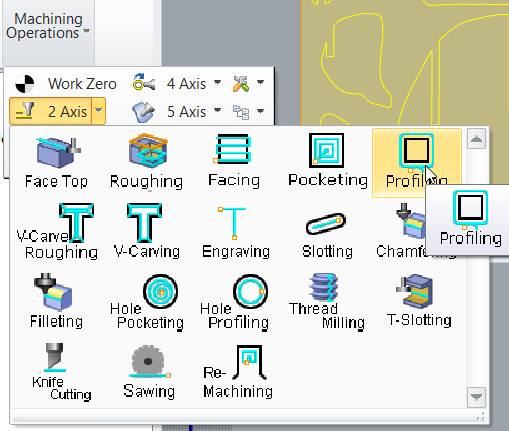
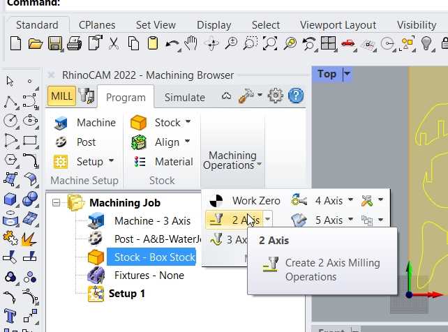
| Go to MACHINING OPERATIONS -> 2 Axis -> Profiling: And set all the displayed parameters. |
| CUT LEVELS: location cut geometry at top and Cut level ordering to Depth first. Set Total Cut Depth = Stock value in mm + 0.5mm (Rough depth to 7mm and Finish depth will be set automatically). Rough Depth Cut = less that 1/2 of the diamenter of the endmill. Finish depth = 1mm (In our case). |
| ENTRY/EXIT PARAMETER: We set along path for Entry and none for Exit. DO NOT PRESS GENERATE, just click on the next parameter. |
| ADVANCED CUT PARAMETERS: Remove cut arc fitting and add bridges/tabs. |
| CORNERING PARAMETERS: External corner type Round (Default) and internal corner type Dog Bone. |
| in TOOLS, set your tool properties. |
| FEEDS and SPEEDS:Direction = Clockwise. You need to calculate your CUT= Chip load (0.15) x Nº of flutes (2) x RPM (16.000) = 4.800mm/min |
| CLEARANCE PLANE: Automatic. |
| CUT PARAMETERS: In our case we used conventional cut direction and outside for closed curves. |
| Once our settings are configured, it´s time to simulate and check the toolpath. |
 Machining operations.
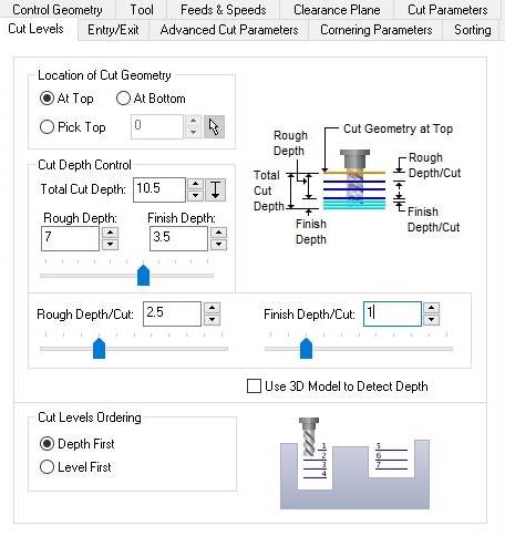 Cut levels.
 Advanced cut parameters.
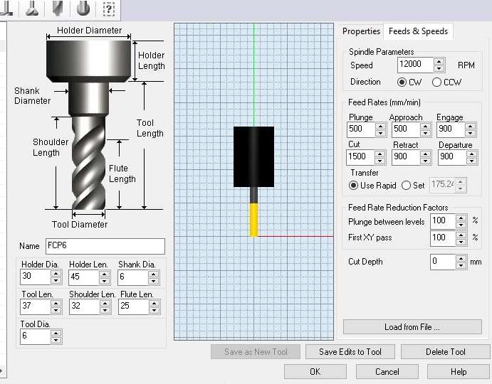 Tool.
Tool.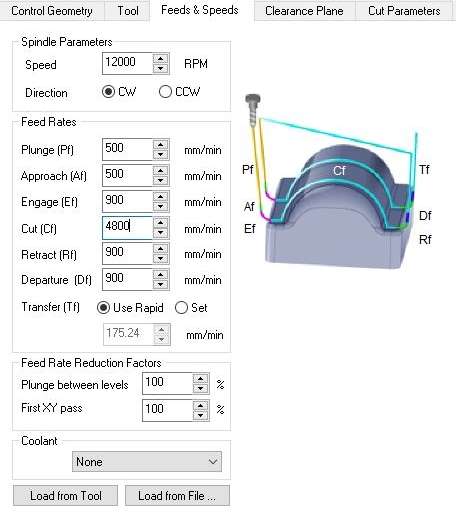 Feeds and speeds.
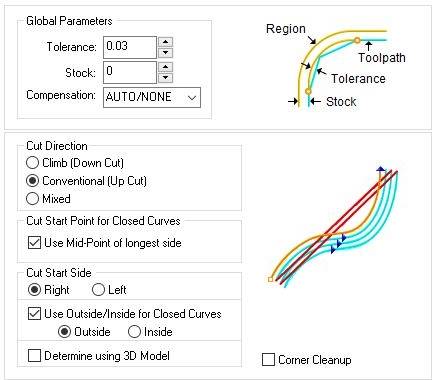 Cut parameters.
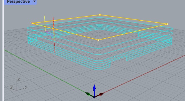
THIRD: SIMULATING AND TOOLPATH VIEW. The last step with RhinoCAM is probably the most important. It´s were we´re going to check that our settings are correct by reviewing the toolpath and the machine time information, and in case we find errors or our simulation doesn´t run properly, we have the opportunity of changing tha parameters needed.
| Once finished setting parameters: GENERATE. |
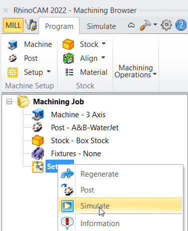
| Go to Program: Select the new folder that´s been generated, right click and simulate. |
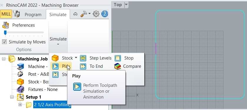
| Once the simulation is done: Go to SIMULATE to check the toolpath and to change speed preferences if needed. |
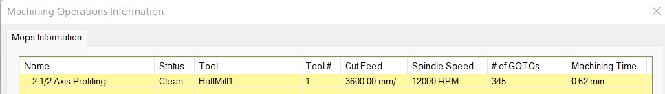
| When you´re in the folder that´s been generated: Instead of clicking simulate, click INFORMATION to get a time estimation. |
| If everything is correct: Go to POST and export your file. Now we can open our file in our CNC machine. |
Once we´ve designed, set all the parameters and checked that the toolpath is correct, we can export our file. To do so, we just have to select our generated folder and press POST. For reminder: if you load more than one folder at the same time, be careful with the loading order because it will affect the cutting order too!
As for how we´re doing for now. This week is a big rollercoaster, steep hill learning curve! we´re going well, understanding the whole process, but still going slow. We expect that once we´ve practiced the process completely a few times, we´ll start to feel more comfortable. But the good thing of starting slow is that we´ve had no issues. So let´s continue!
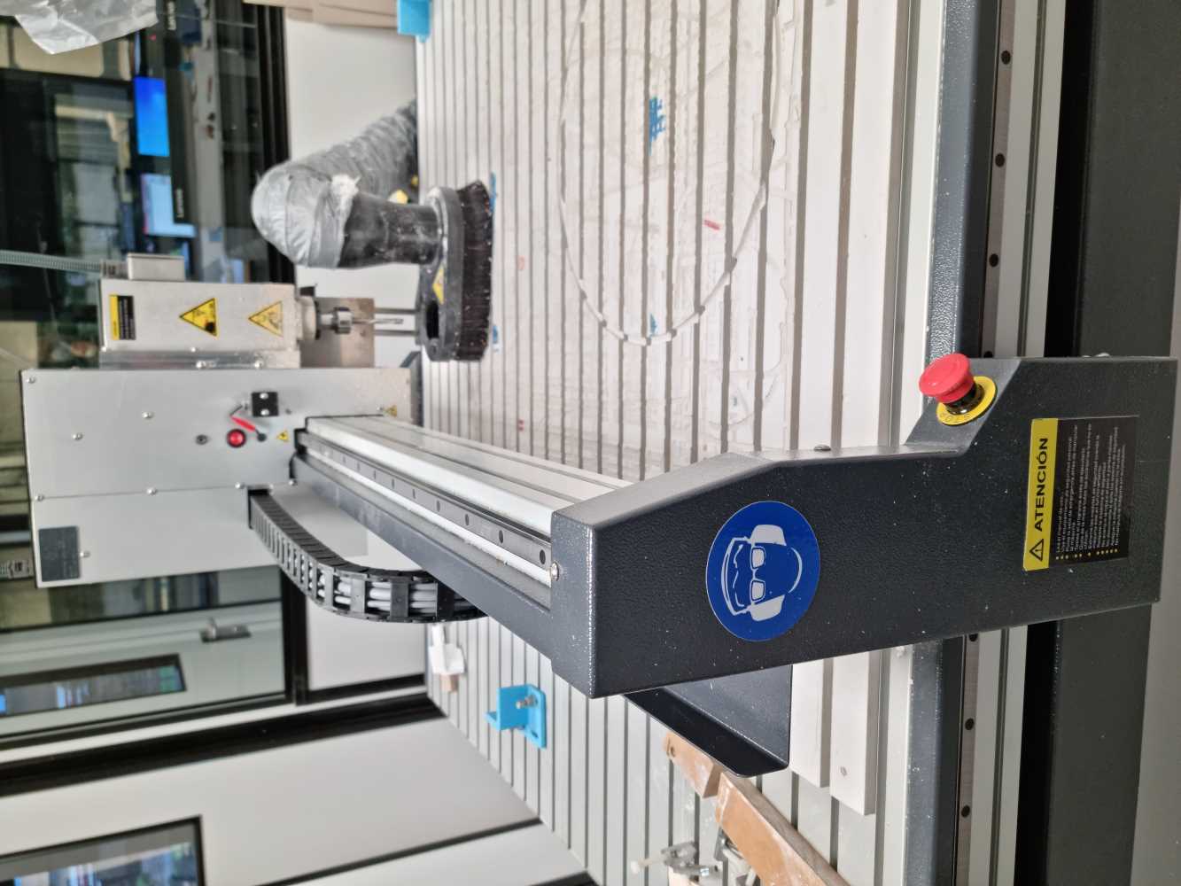
3. SAFETY SETTINGS
Before loading our file to our CNC milling machine, We go were our CNC is with our instructor Alberto, who explained us the safety procedures and measures to be followed when operating a CNC milling machine:

SAFETY PROCEDURES
- Never work with the CNC by yourself: Always with the supervision of a technician.
- Mandatory use of eye protection.
- Gears and drive belts must be protected by covers.
- All checking, measuring, adjusting, etc. operations must be carried out with the milling machine stopped.
- When operating the milling machine, do not get distracted at any time.
- The clamp or workpiece clamping device must be firmly fixed to the milling machine table.
- The milling cutter must be well positioned on the spindle axis and firmly clamped.
- The table must not encounter any obstacles in its path.
- There must not be any abandoned parts or tools on the milling machine table that could fall or be reached by
the milling cutter in its movement.- Hands should be kept away from the milling cutter.
- All checking operations, adjustments, etc., must be carried out with the milling machine at a standstill.
- Never remove the protective guards.
- Never remove shavings by hand, use a brush or a squeegee. Chips must be removed when the machine is stopped
and must be removed regularly, not only at the end of the work.
4. CNC MILLING MACHINE TEST RUN HANDS ON
Now that we´ve got a basic knowledge of what to do, and what not to do, and following our instructors recommendations, we get hands on!
| FIRST: Set the machine to its HOME position. |
| SECOND: Fix the material to the milling machine table. The clamping devices must be firmly attached. |
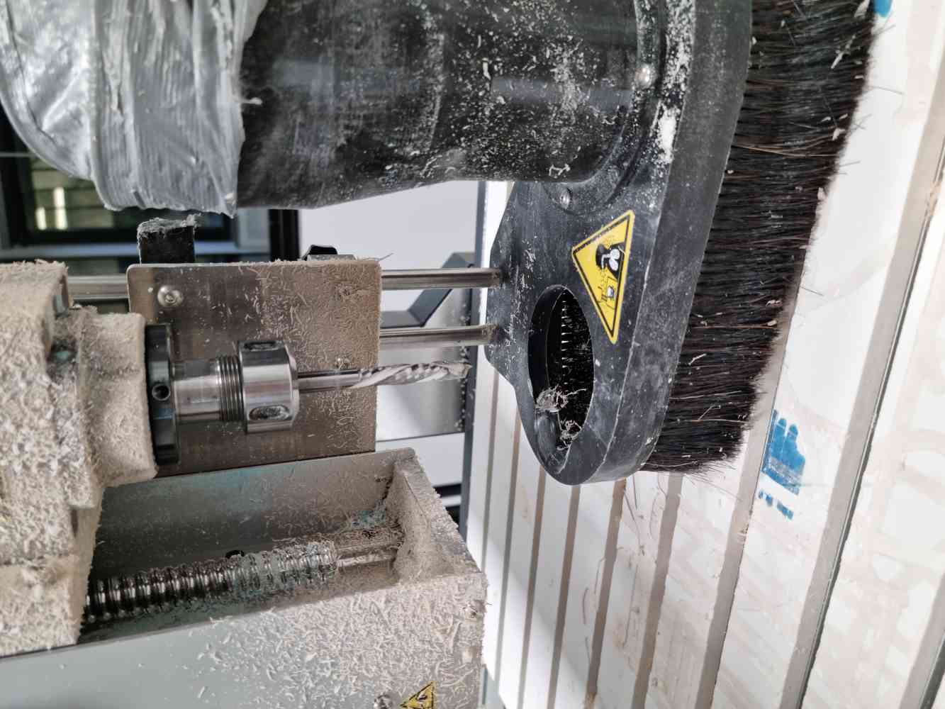
| CHANGE ENDMILL: Change endmill if needed. Remember to change the endmill and the cone too. |
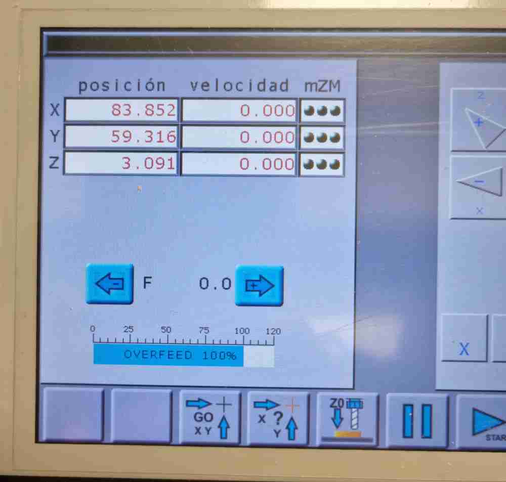
| SET XY AXIS with the laser: Set to the desired position and SET ZERO -> Laser -> OK. Don´t forget to turn off the laser. |
| Calibrate Z Axis with the PROBE: Connect the probe, and set it to the desired position. Once it´s close we press Z0 probe calibration. |
| Once it´s set, we can start the routine inside our design area: To avoid hitting our campling devices. |
| UPLOAD FILE: Go to main menu and press START -> FILE FROM USB -> SELECT. |
| GO TO MAIN MENU AND PRESS MAND (Mandrel): The mandrel must heat up for at least 10 minutes. |
| Once the Mandrel is ready stop it and TURN ON THE VACUUM: and press START cutting. |
| When we start the millig, we get out of the room and stay watchfull from the window, close to the emergency stop button |
 Home position.
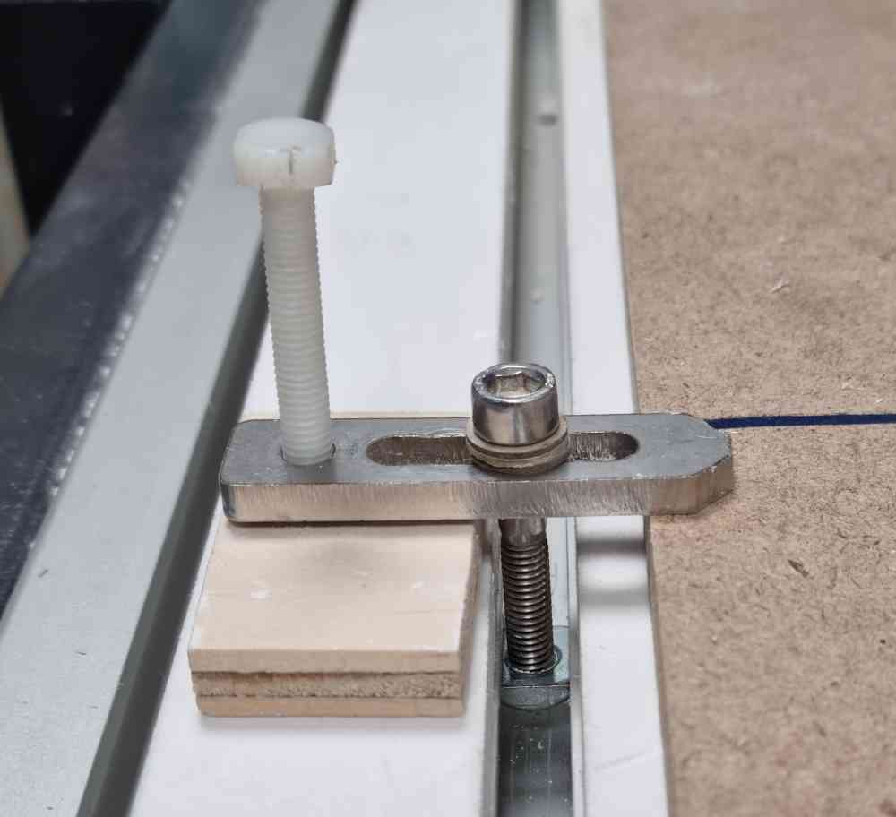 Fix the material.
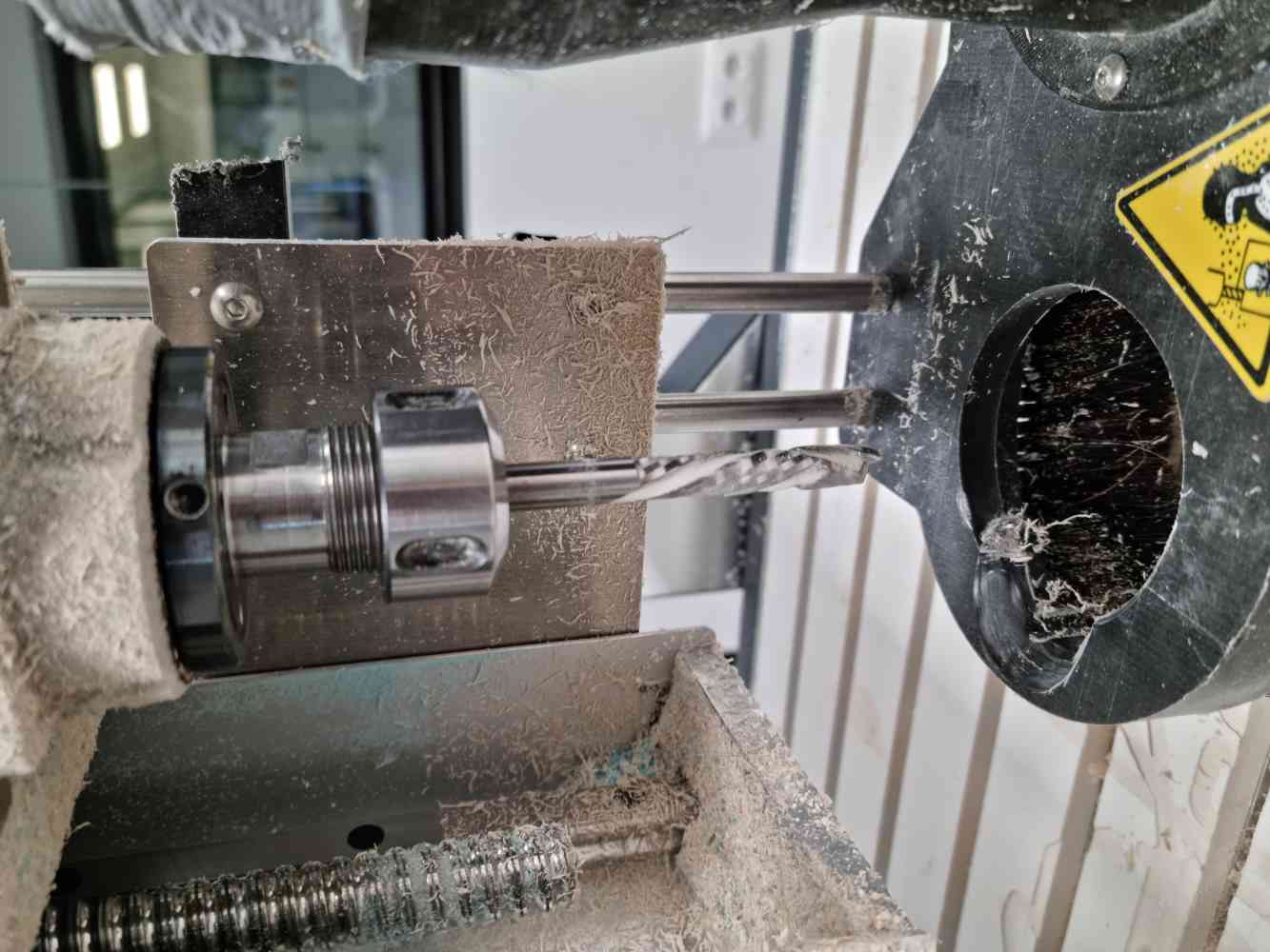 Endmill changing.
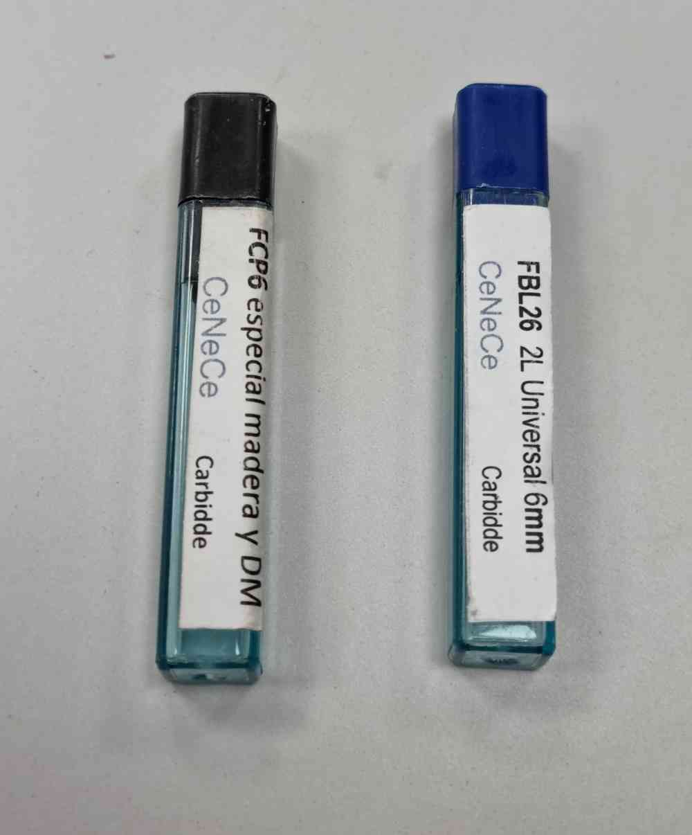 Endmills.
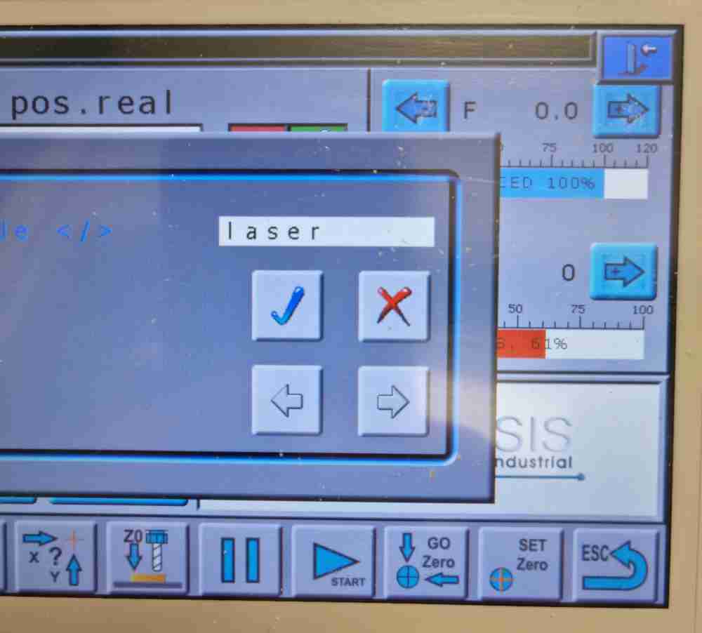 Laser XY calibration.
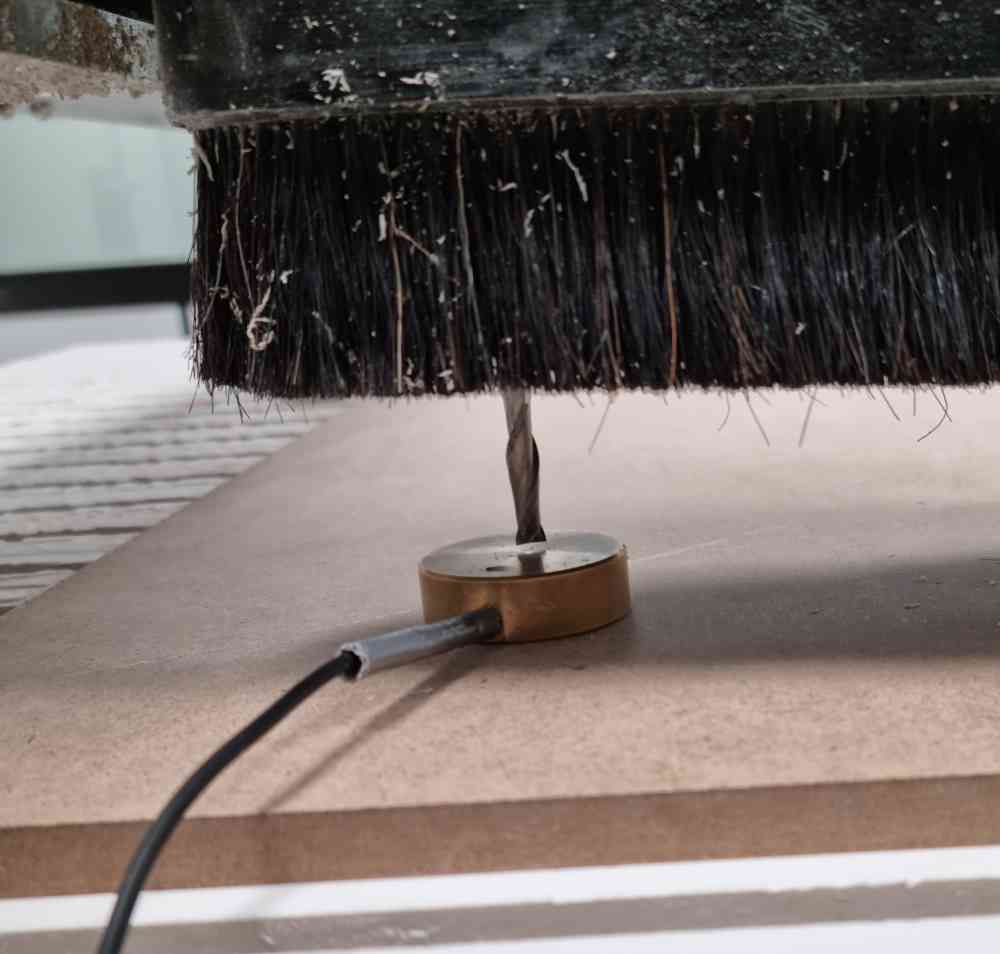 Z calibration with probe.Z0 calibration.
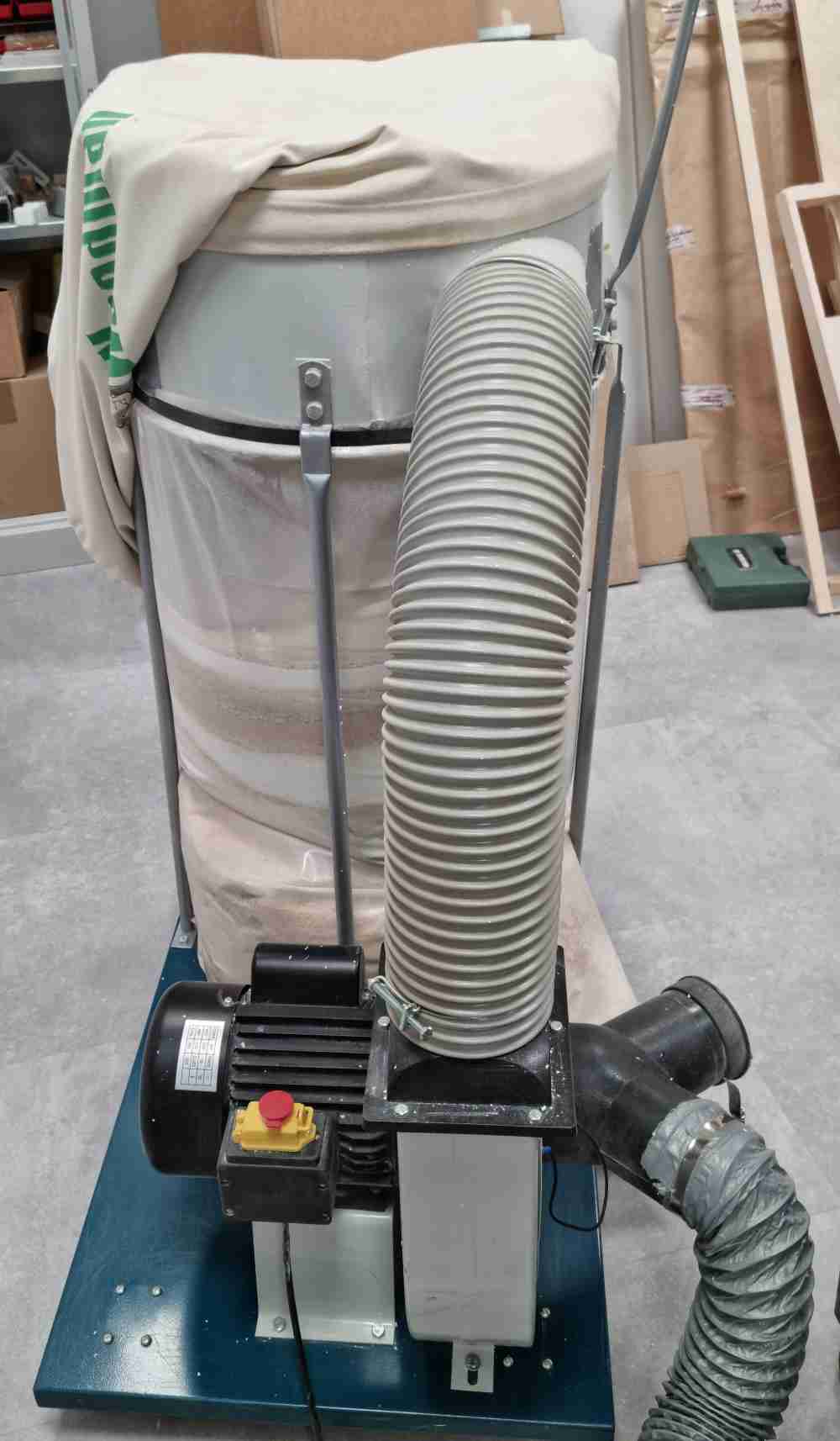 Turning on the vacuum.
For our first hands on machine preparation, everything went well, we spent the time we needed and supervised every step twice. Even that, we nearly forgot to turn on the vacuum! After fixing the material, changing the endmill and adjusting the XY and Z axis we did succesfull cut air test run. So, after that we cutted our small design. Thre results were quite good and we got nearly a perfect cut, having 50mm wide and 49.9 of height square. So now, we´re ready to prepare our own designs!
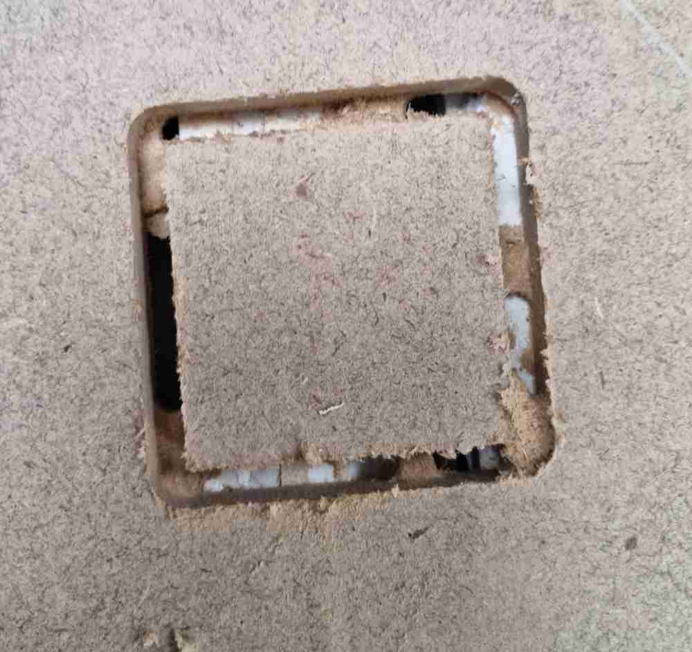 Square design with bridges.
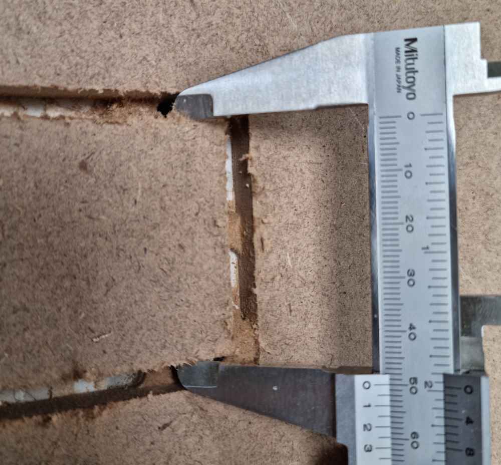
MATERIALS, TOOLS AND SETTINGS
- Material: 10mm MDF.
- End mill: FBL26, 6mm, 2 flutes.
- Software used to set parameters: RhinoCAM.
- Cut speed: 4800rpm.
- Conventional cut direction.
- Cut depth and total cut depth: 2.5mm and 10.5mm.
- Rectangular bridges.
- Measurement=49.9mm (Square size=50mm)
INDIVIDUAL ASSIGNMENT
For the individual assignment, we had to design, mill and assemble something big. For the past weeks, trying to design things related to my area of knowledge (healthcare) has helped me to get inspiration and extra motivation. But this week it´s been different. I first tried to design by myself a human skeleton to be milled afterwards, but soon I figured out it was more than one spiral away of my capabilites (I´m a newbie in CNC milling). But beyond giving up, I gave it a second try, and while we´re at it, this time learning and experiencing with Slicer for Fusion 360, a program i´ve been interested in since 3D printing assignment. Before getting our first hands on, I also reviewed Lorena Delgado´s respository, because she also used this program last year.
But, what I didn´t expect is that I was going to get so stuck with this combination of anatomical segments + slicer for fusion, it gave me hours of headache and great learning curve. First I had to obtain my anatomic models from 3D slicer (as seen on 3D printing week), and afterwads learn (by doing) how to use fusion slicer with such complex designs. At the end I had to let it go, as I was spending too much time in a step that wasn´t relevant for achieving my individual spiral goal (I´ll come to it later, if I have time left).
The good thing about this is that I learned a lot and passed with confidence the learning experience with fusion slicer, Rhino and even fusion 360, as you can read later, and that basis helped me prepare, mill and assemble my final design in a "comfortable" and enjoyable way.
Here you can check my first unsuccessful experience with slicer for fusion and anatomic segments:
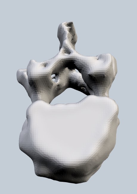 designed vertebra.
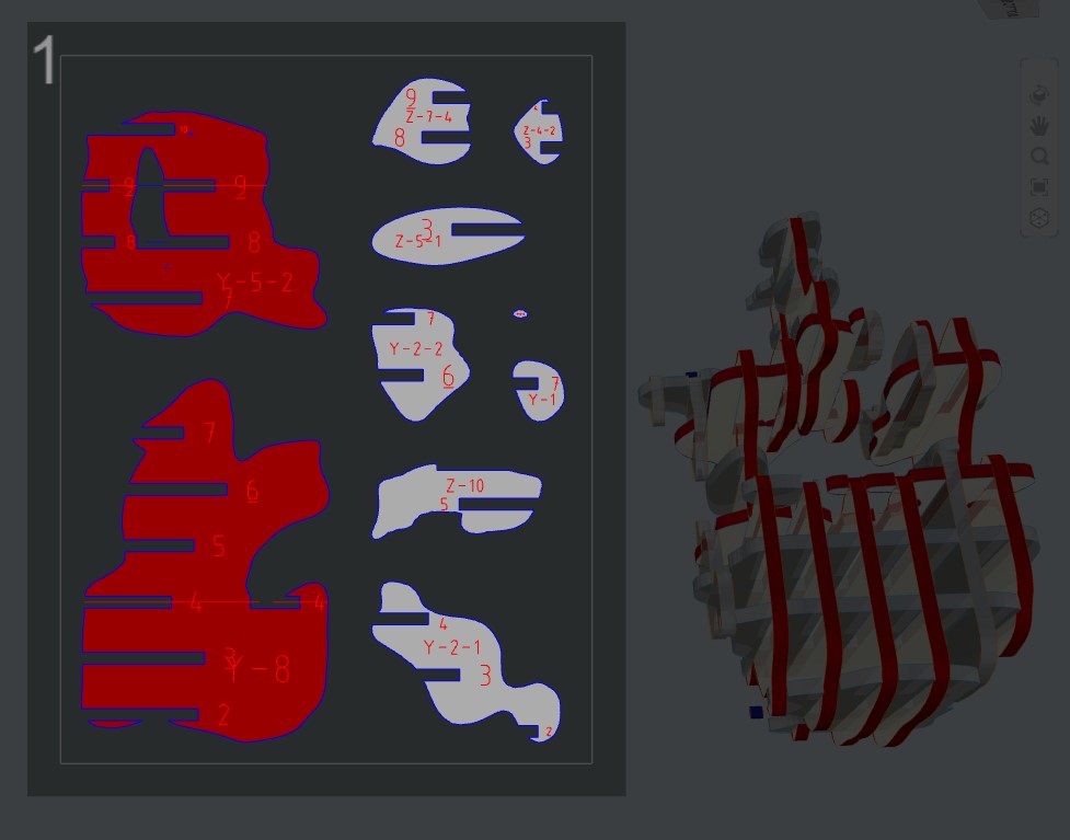 Slice errors.
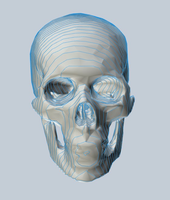 Designed skull.
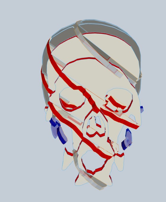 Slice notches.
Once I learned the lesson, and thanks to my fabmate Jon Merino, I quickly focused again thank´s to his support, his practical way of approaching fabacademy and by sharing with me his experience with creating forms in fusion 360, and combining it with slicer for fusion, in order to get quite nice designs! So thank´s Jon, and this is how it went:
DESIGNING WITH FUSION 360 AND SLICER:
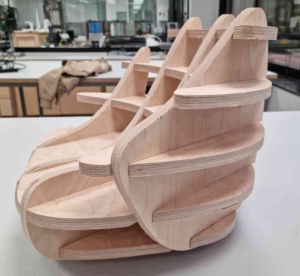
My goal, for designing the object i´m going to mill, is to design it first on fusion 360, and afterwards prepare it for millin using all i´ve learned in slicer for fusion. So as i´ve already used fusion before (you can check past assignments), this time I went straight to SOLID, create FORM. In my case I selected a box, and modified it as desired until I got the shape that I wanted, a puff chair for my kids:
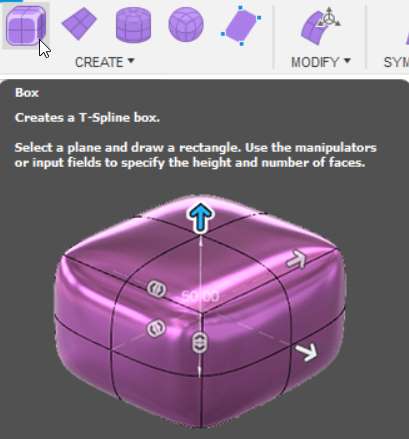 Create T-spline box.
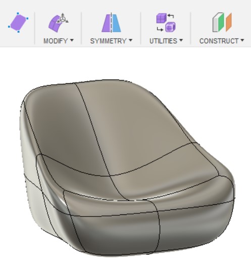 Modify as wished.
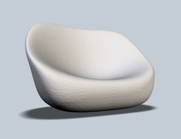 Final puff design.
Now that i´ve got my design in fusion. We export it as an .obj file and open it in slicer for fusion. The goal now is to prepare the file for milling adjusting size, construction technique, slice distribution and relief type. Here you can check the steps I made:
| Import .obj file from fusion. |
| Configure the Manufacturing settings: Configure the dimensions of your material size. Check the units! |
| Adjust object size. |
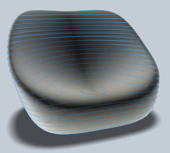
| Select construction technique: In my case I chose CURVE, because it fitted best. You will have to check for slice errors every time you change your construction options. |
| Adjust your slice distribution: Now we need to adjust our slices in order to get the best result for us, with O slice errors. |
| Select your relief type: I selected Dog Bone as it seems that´s the one that works better. |
| Adjust advanced settings: If you don´t get to fit your design properly, you can edit your slice directions or modify your form with the aim of getting the best results. |
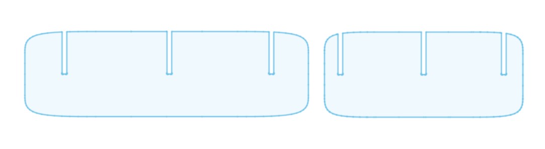
| Before exporting your file: go to GET PLANS and check the cut layout carefuly. Take care that the dog bones are correct, that they have enough space and that there are no multiple notches or loosen parts. |
| To export: Select .dxf file and check the units!. |
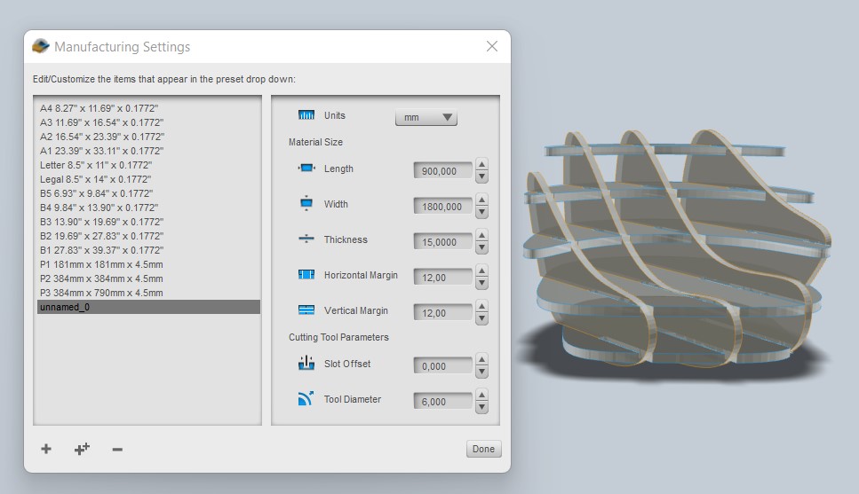 Material dimensions.
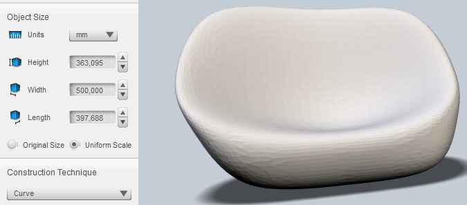 Object size.
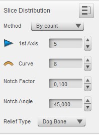 Slice distribution.
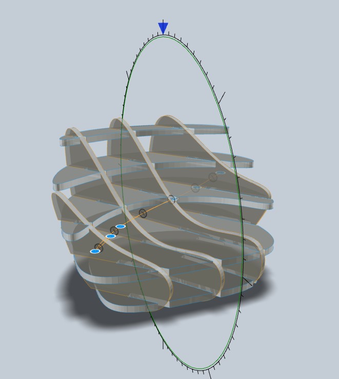 Editing slice direction.
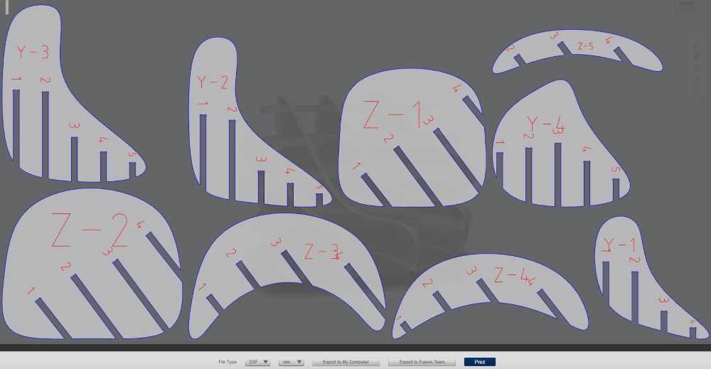 Plan layout.
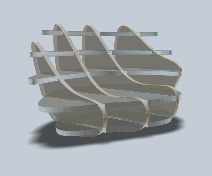
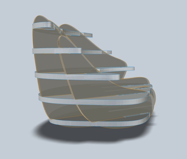 Final design.
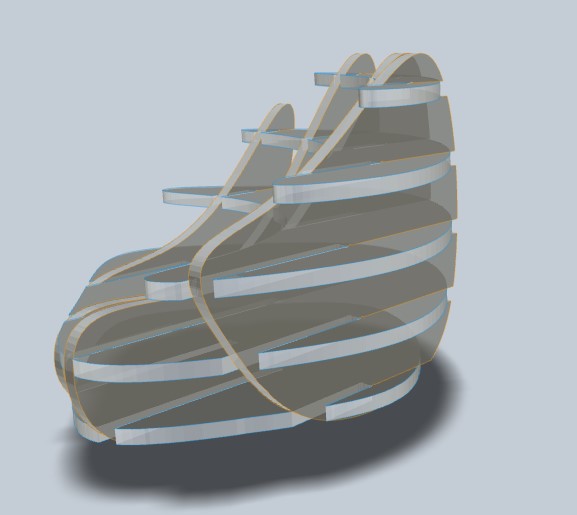
Once exported, we can´t just open it in RhinoCAM, we have to edit the file first so it will run properly in Rhino. In my case, I opened the .dxf file in Fusion 360 and deleted both annotation and frame sketches first and nested the objects to a better fit after. Now, you have the file ready to export your final .dxf which is ready to open in Rhino.
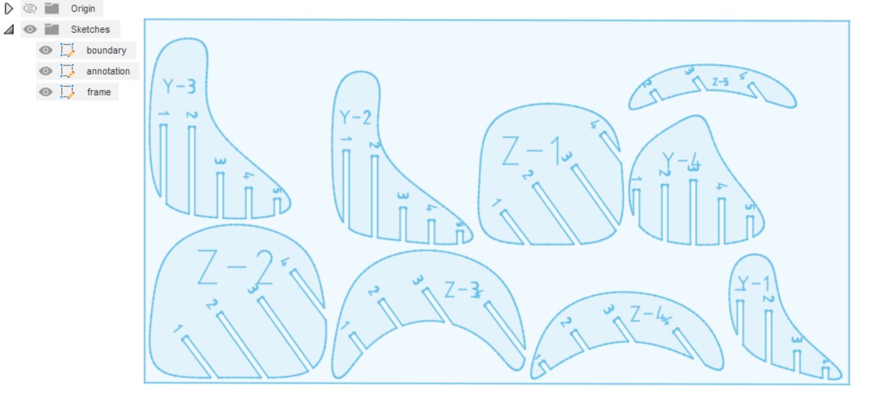 Delete anotation and frame sketches.
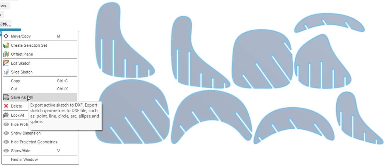 Export as .dxf.
As you can observe the nesting process in slicer is TERRIBLE.. I tried deepnest but I couldn´t make it work, so finally I had to check it by hand, and I now that it can improve a lot, but i´ve 0 experience. So, if you intend to use slicer, remember to use an alternative nesting software! And in my case, i´ll check for usefull nesting programs for CNC milling.
Now, we can open our final file in RhinoCAM, configure the settings and prepare our file for launching it to our CNC:
CAM SETTINGS FOR THE PUFF CHAIR:
| MATERIAL: 15mm MDF. |
| END MILL: FBL26, 6mm, 2 flutes. |
| ENTRY/EXIT PARAMETER: Set along path for Entry and none for Exit. |
| ADVANCED CUT PARAMETERS: Remove cut arc fitting, and 5 bridges per object. |
| CORNERING PARAMETERS: External corner type Round (Default) and internal corner type Dog Bone. |
| FEEDS and SPEEDS:Direction = Clockwise. Cut speed = Chip load (0.1) x Nº of flutes (2) x RPM (16.000) = 3.200mm/min |
| CLEARANCE PLANE: Automatic. |
| CUT PARAMETERS: Conventional cut direction and outside for closed curves. Cut depth = 2.5mm and total cut depth = 15.5mm. |
| MACHINING TIME: 1hr 28min. |
MILLING, SANDING AND ASSEMBLING:
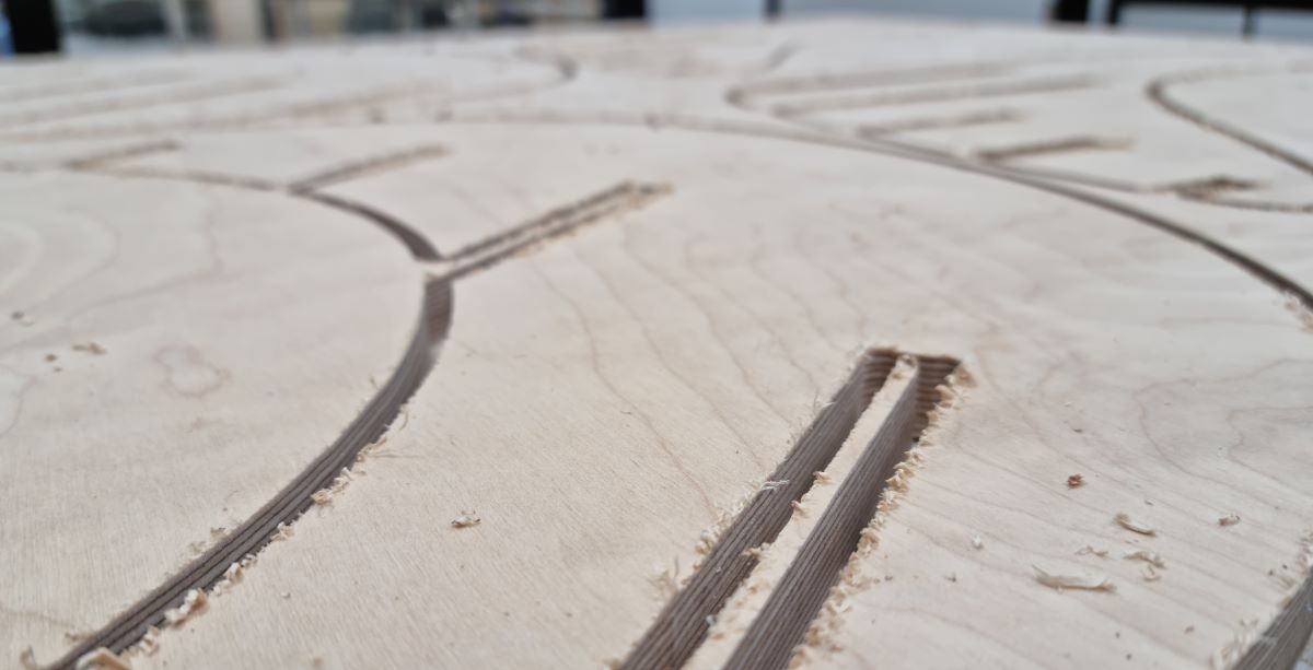
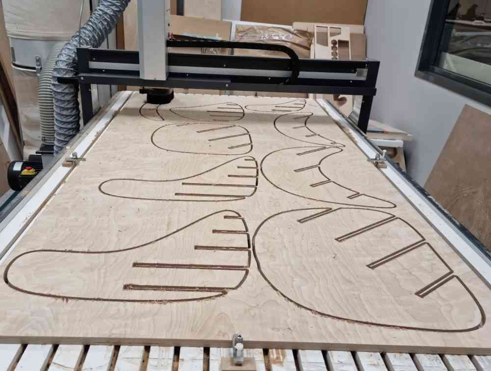
This is how it looked after milling, I had no issues during the process. I had to add 0.1mm more to the depth cut to be sure that it cutted the whole piece and in worked perfectly.
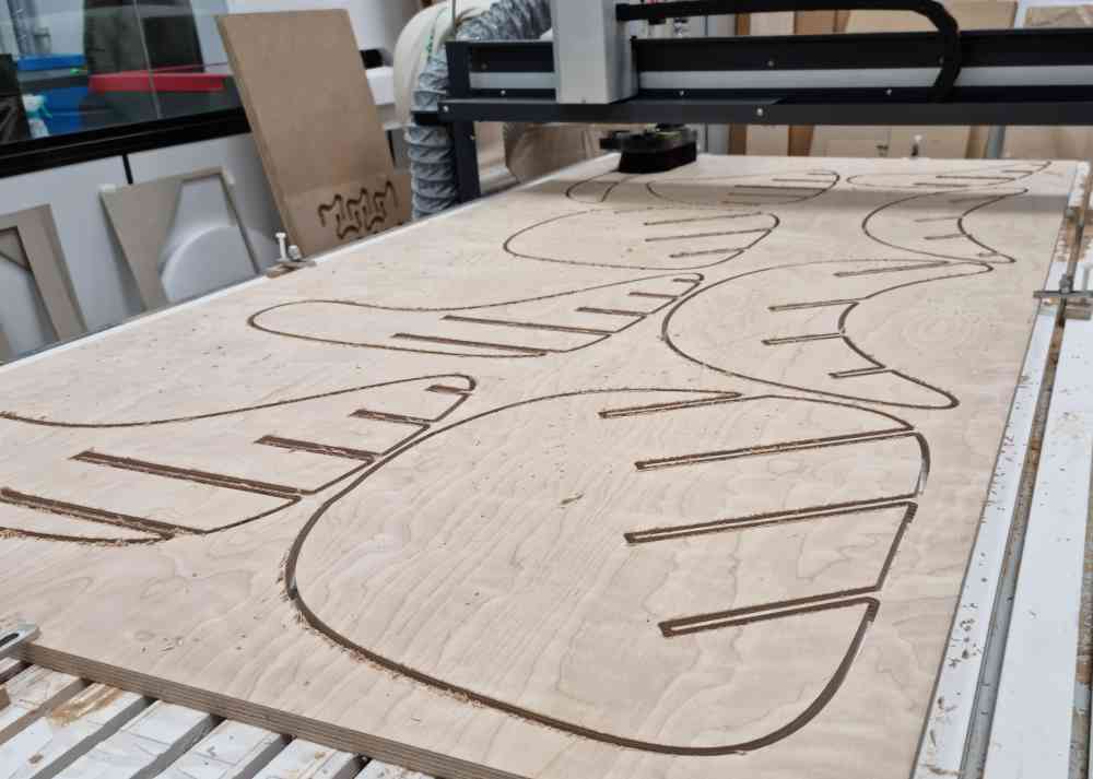 Milled material.
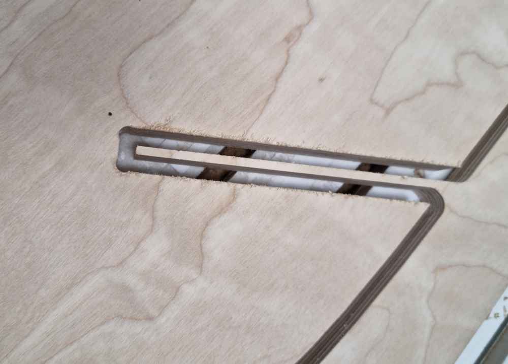 Dog bone.
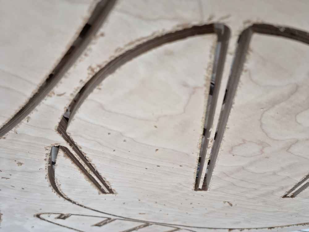
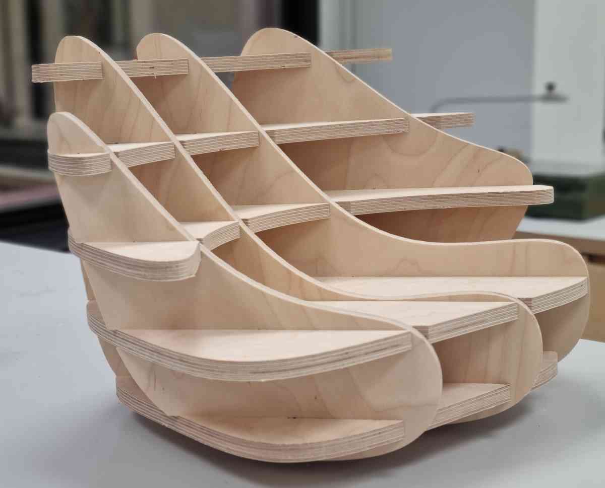
After doing some sanding, I checked the fitting and in fits perfectly with no need of glue. In some sections I had to hammer it to its final position, so it´s firm and stable.
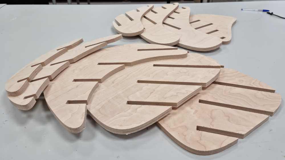 After sanding.
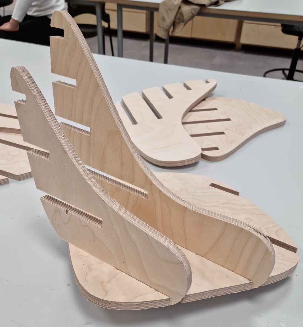 Checking the fit.
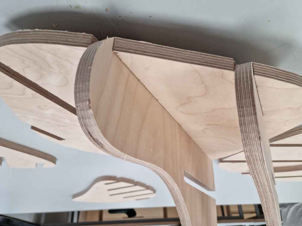 Assembling.
Here you can see the design after assembling it.
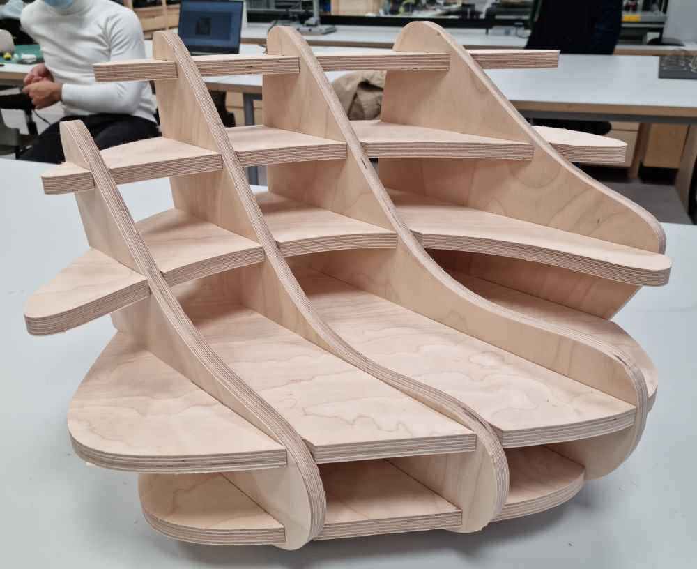 Final design assembled.
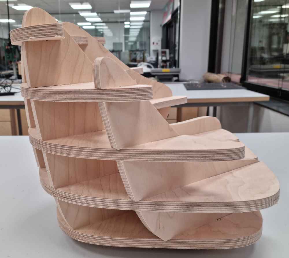
Download the .f3d file created: kidspuff fusion .f3d
Download the .f3d file created: kidspuff nesting .f3d
Download the .dxf file created: kidspuff.dxf
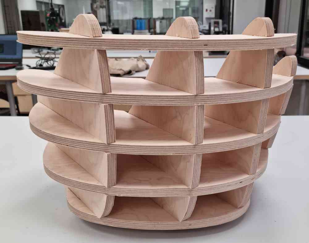
EXTRA DESIGNING:
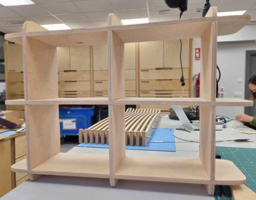
As i´ve got a time and material, i´ve also designed a shelve for my kids room using fusion 360 and slicer for fusion. Here you can see the design and the final results, following the process described above:
CAM SETTINGS FOR THE SHELVE:
| MATERIAL: 15mm MDF. |
| END MILL: FBL26, 6mm, 2 flutes. |
| ENTRY/EXIT PARAMETER: Set along path for Entry and none for Exit. |
| ADVANCED CUT PARAMETERS: Remove cut arc fitting, and 5 bridges per object. |
| CORNERING PARAMETERS: External corner type Round (Default) and internal corner type Dog Bone. |
| FEEDS and SPEEDS:Direction = Clockwise. Cut speed = Chip load (0.1) x Nº of flutes (2) x RPM (16.000) = 3.200mm/min |
| CLEARANCE PLANE: Automatic. |
| CUT PARAMETERS: Conventional cut direction and outside for closed curves. Cut depth = 2.5mm and total cut depth = 15.5mm. |
| MACHINING TIME: 22 min per file (3 files). |
| MEASURES: 920x260x620mm. |
Download the .f3d file created: shelve fusion .f3d
Download the .f3d file created: shelve nesting .f3d
Download the .dxf file created: shelve.dxf
 final distribution.
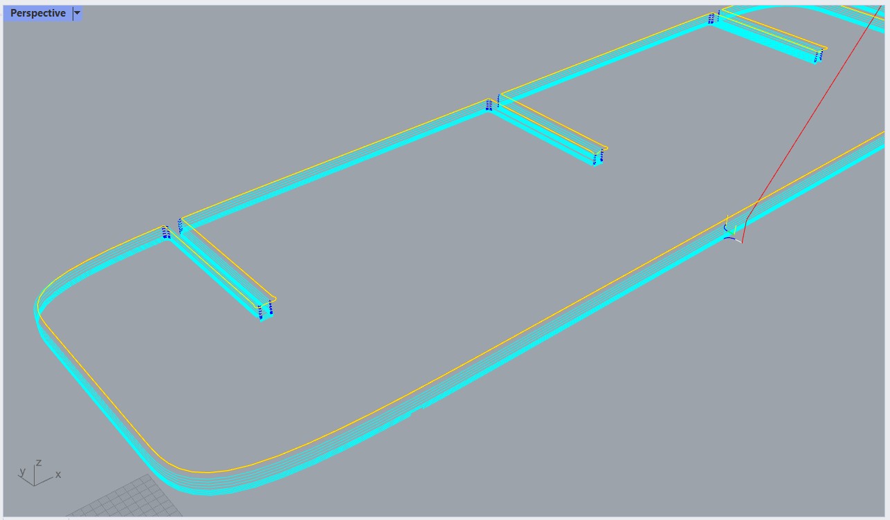 reviewing toolpath.
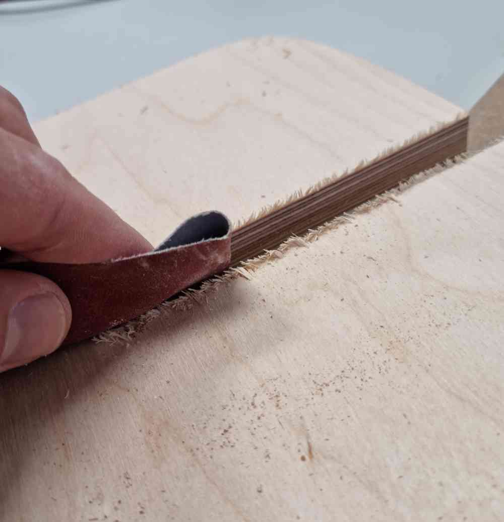 sanding.
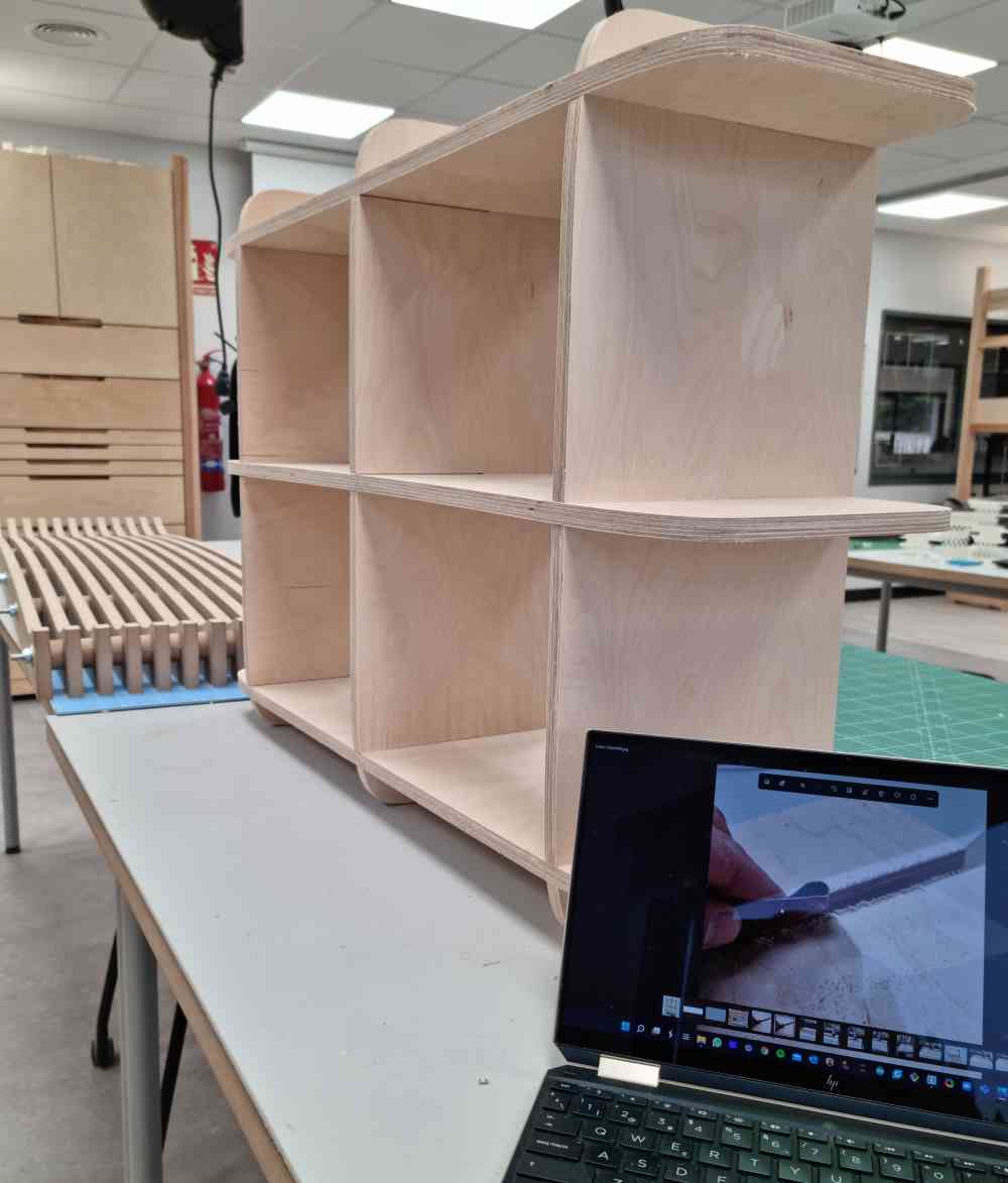
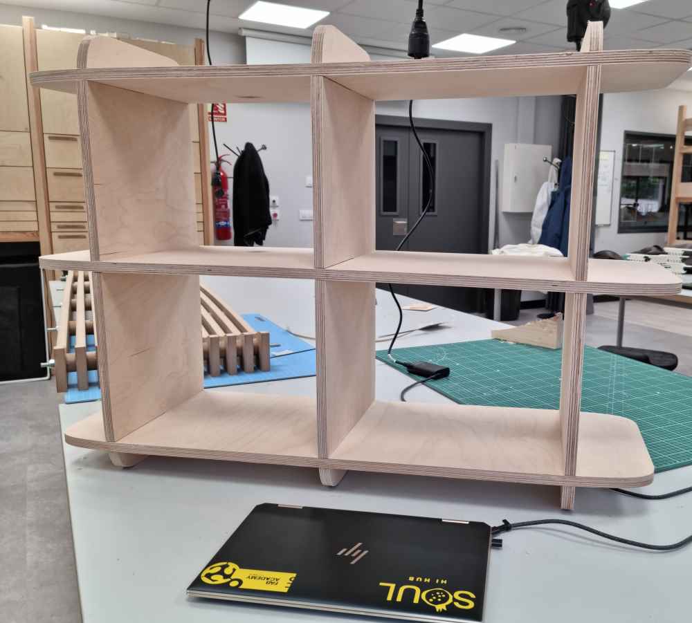 final shelf.
For this simple but functional design, I had no milling issues. It fits firmly and no glue needed! So happy with my second and last design for this weeks assignment.
This week is by far the most demanding week i´ve done in fabacademy. In my case, I experienced an incredible high and slow learning curve, with the need to master design programs such as Rhino and Fusion Slicer combined with the strict CNC milling process. But, as every week, finally all the pieces come together and In a few hours you get the final job done, without issues, with confidence and of course enjoying it! (PD: I have to say that I´m enjoying every step of fabacademy, regardless of difficulty or learning curve).
Back to top