Week 6: Electronics design
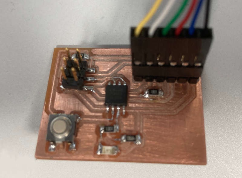
Table of Contents
Group assignment: use the test equipment in your lab to observe the operation of a microcontroller circuit board
This is the group assignment page. Anyway it is no very long and I published here too:
We tested the lab test equipment , the Tektronix TDS 210 oscilloscope and the Koban KM838 multimeter.
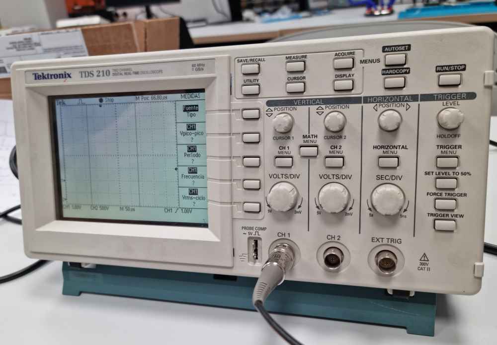
Tektronix TDS 210
The Tektronix TDS 210 is a two channel, 60 MHz, 1GS/sec sample rate digital osciloscope.
We reviewed the main features of the osciloscope, learning the vertical position and scale (volts/div) of both channels, the horizontal position and scale (sec/div) and the trigger. Also we tested the squared signal generator of the osciloscope and showed some measurements on the screen.
Testing the PCB:
We tested the different points of the PCB with the oscilloscope, mainly observing the voltage of each point, and watching how the voltage changes in certain points when we pushed the button and the LED blinked.
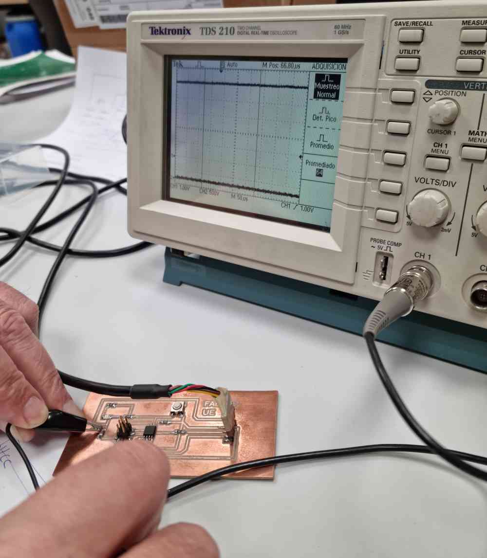
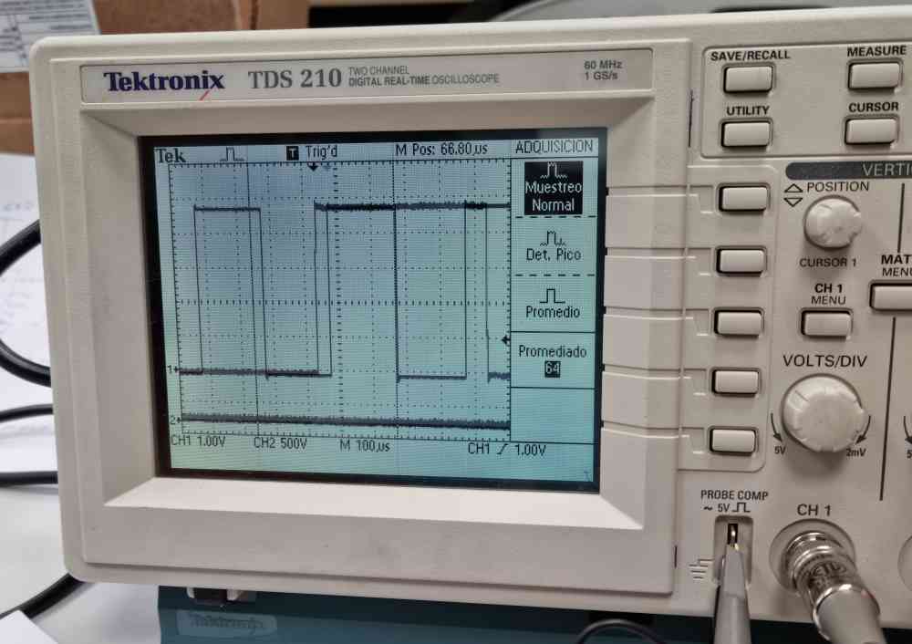
To watch a squared signal and understand better the horizontal an vertical scales and positions, we connected the probe to the squared signal generator of the oscilloscope, so we could see how the pulse width changes with the horizontal scale. We also changed the probe attenuation to "x10". The result was that the signal went down and lost the synchrony, because the peak level was below the trigger level. So we adjusted the trigger level to watch the signal properly.
KOBAN KM838 Multimeter
It's a simple digital multimeter, so we tested DC/AC voltage, some resistors, continuity and diodes.


We also reviewed how you have to test the different parameters. E.g. you can't test the resistors once they are on the board, because their resistance can be affected by the rest of the components. The voltage has to be measured in parallel and the current in a serial configuration.


Images from tecknologyuk.net
Individual assignment: redraw an echo hello-world board, adding a button and LED (with current-limiting resistor), check the design rules, make it, and test than it can communicate
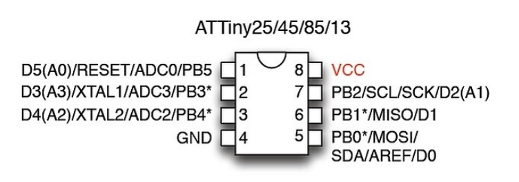
First thing I did was to get the pinout of the ATTiny and the ISP and FTDI interfaces:
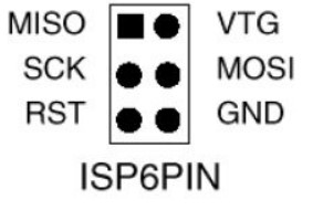
ISP pinout
MISO: Master In Slave Out
MOSI: Master Out Slave In
SCK: Serial clock
RST: Reset
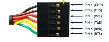
FTDI
Tx: Transmission
Rx: Reception
RTS: Request to Send (not used in this project)
CTS: Clear to Send (not used in this project)
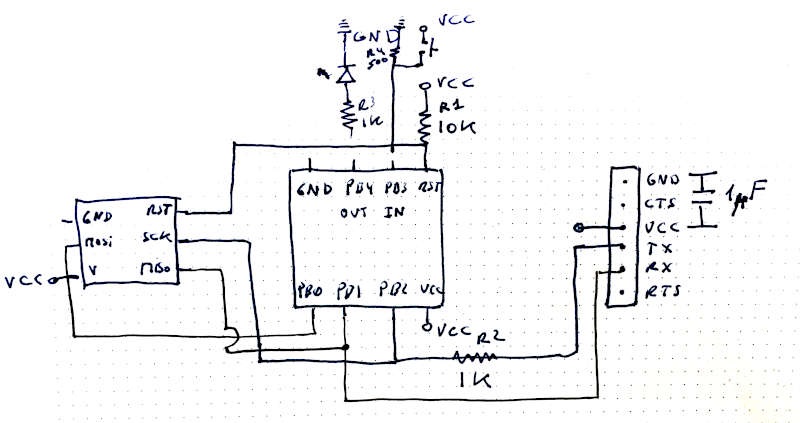
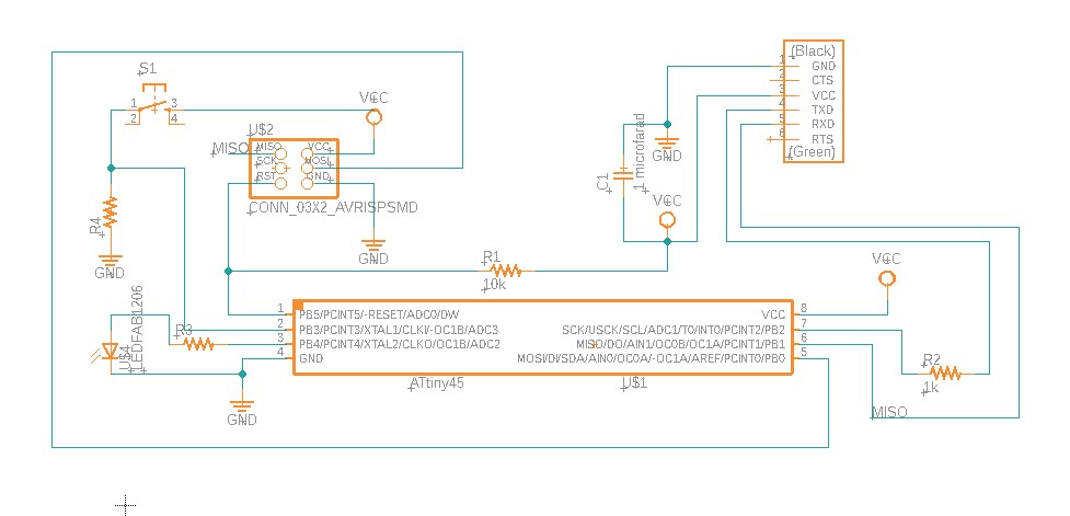
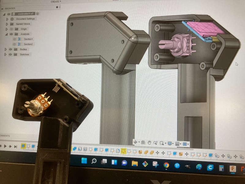
After that I sketched the schematics of the circuit:
And from that I went to the Fusion 360 electronics (Eagle in the past), and installed the fab library and design rules of fabacademy. I had some problems finding the right components. But from the repository of Lorena Delgado I learnt that you have to choose components inside the fab library, and in case of doubt, those marked with "fab" in their name.
I had some problems moving/rotating components, but after some attempts I got it. I connected some lines drawing them, and connected others just naming the line (GND, VCC, MISO, SCK..)
After that I switched to the board and I had some fun trying to solve the puzzle.
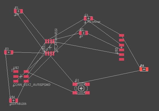
I tried the automatic routing, just to see if it worked, but it generated some circuits on the other side of the board, so I started to do it manually.
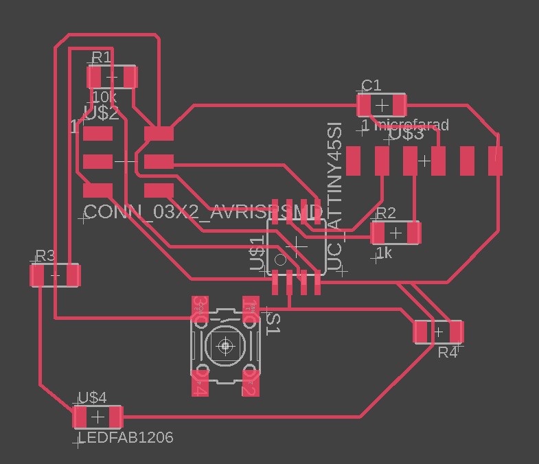
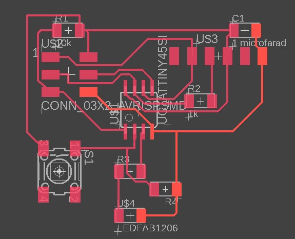
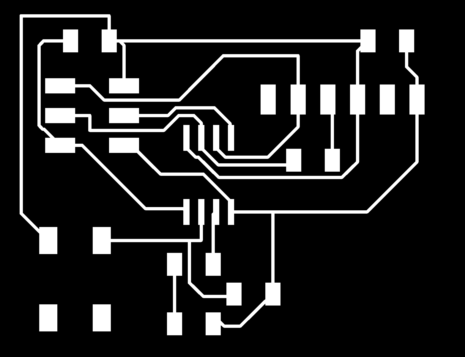
I was very proud of my result, but I realized I had missed one of the lines. So I spent some time arranging it to get the final result:
I liked the feature "View->Show", to highlight a specific line (GND in orange in this case)
I got it without having to make "bridges", and making it as compact as I could (40x30 millimeters).
Here is the file of Fusion360 electronics (Eagle).
I didn't know how to export the file to .png in an easy way. It's a little bit tricky, because you don't find it on the Fusion360 menu. You have to go to the command line and type "export". A drop down menu appears with the option of exporting it as an image. Click the checkbox "monocrome" and set 1000 dpi to export it.


You can download the file here.
So on friday I went to the lab to make the PCB. I tried to learn from my past errors (origin setting, board bent), and use the settings we had two weeks ago.


At the beginning everything seems to be all right, setting mods with the same parameters we used two weeks ago, thanks to the impressive documentation Pedro Chana had made of our group assignment.
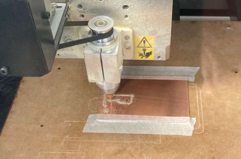
So I only had to cut the outline and it's done. But then this happened: the router began to trace a line just crossing my amazing new circuit!
What had happened?
I had saved the outline file with 150 dpi instead of 1000 dpi. So the corner of the outline rectangle is that beautiful line that crosses the circuit.
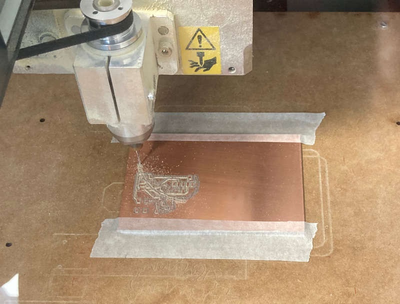
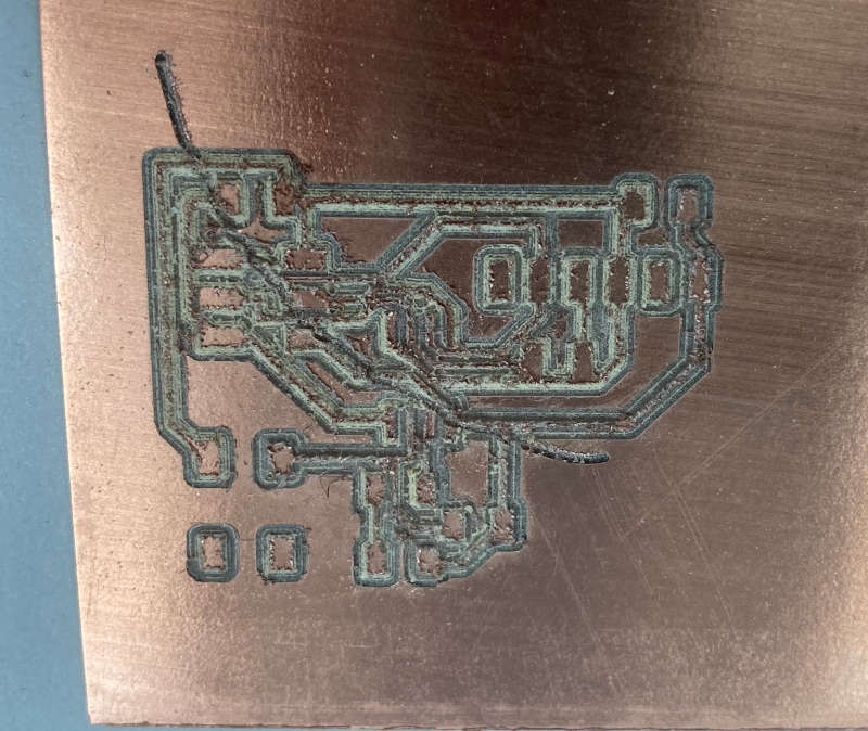
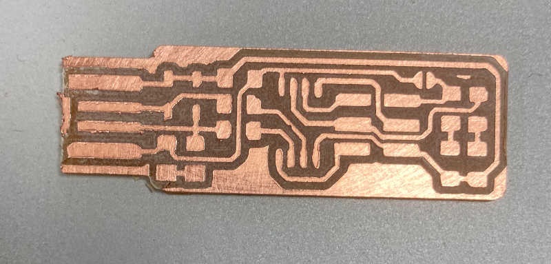
After that I decided to use a trick that our instructor Alberto told us: to cheat the Z calibration putting something below the probe, so we can "cut in the air". And good thing i did, because after adjusting the file to 1000 dpi it was again tracing inside the circuit. What happened this time? I had to go back and forth in mods, and I didn't realize that the model of the Roland had changed to MDX20 instead of MDX40. Due to the different size of both machines I was cutting a smaller version of my circuit. After changing it to MDX40 I finally got the PCB:
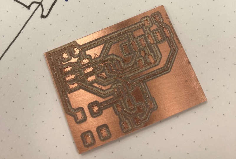
Some of the lines were touching some nodes, so i took a cutter to pull them apart, and checked the continuity of all of the traces.
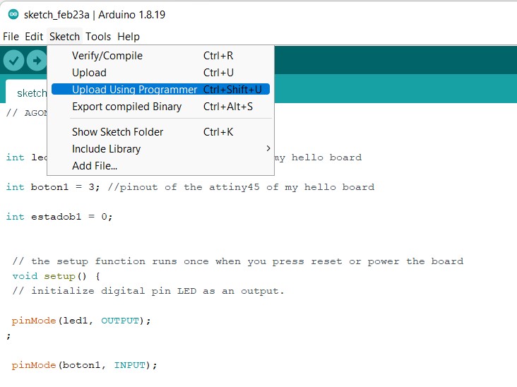
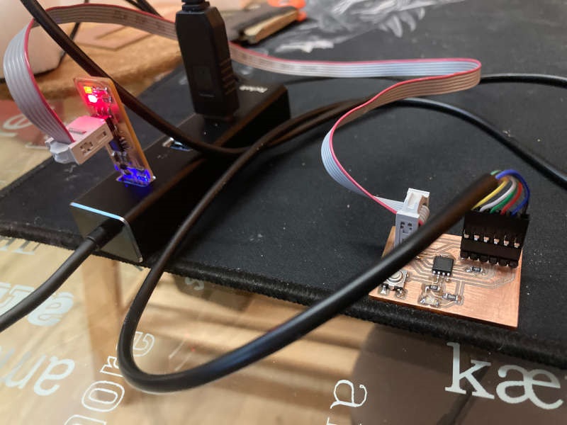
After that I soldered the components and went to program it. I had installed and configured the Arduino IDE for the ATTiny two weeks ago, so it was quite straight to program the board.
The programming went well, but the led didn't switch on when I pushed the button. I took the multimeter to check all the voltages, and discovered that the input pin didn't change the state when I pushed the button. After that I checked the continuity of the lines, and went over the solders of the button. After I did it, the circuit worked fine!

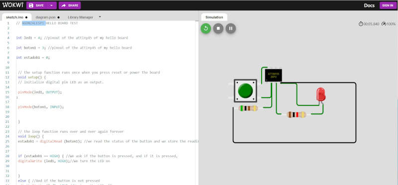
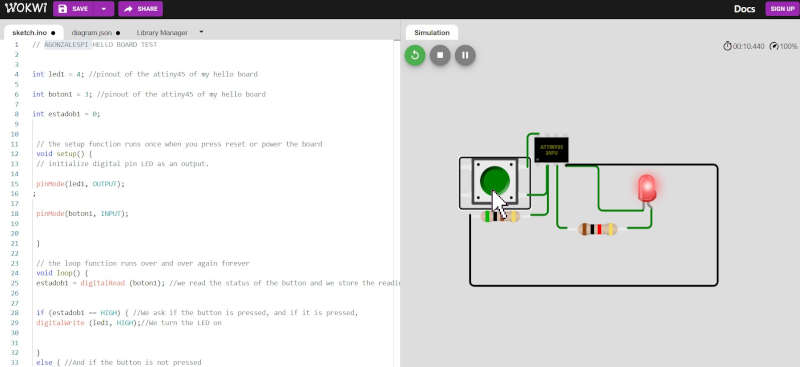
Circuit simulation
I found a good online tool to simulate circuits with micro-controllers, Wokwi. So, I selected ATTiny85 (ATTiny45 wasn't available), and made the same circuit I made physically. After that I upload the code for the switch and LED and it worked perfectly: