Week 12: Input devices

Group assignment:
Probe an input device's analog levels and digital signals
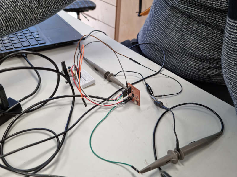
Pedro Chana and I probed together the analog levels and digital signals of his project and mine. His probe is detailed on the group assignment page. Mine is here:
We also tested the values of the motor throttle I did:
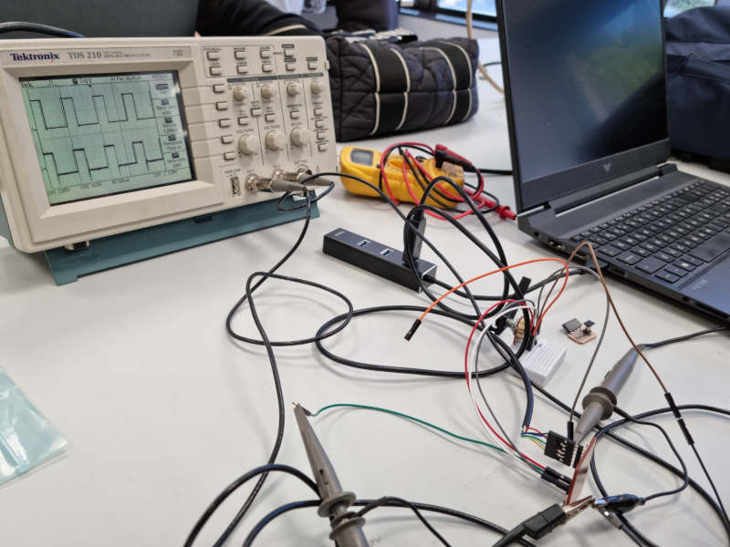
Analog signal:
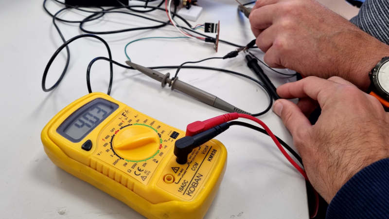
The voltimeter measured values that go from 2.75 to 5V.
Digital signal:
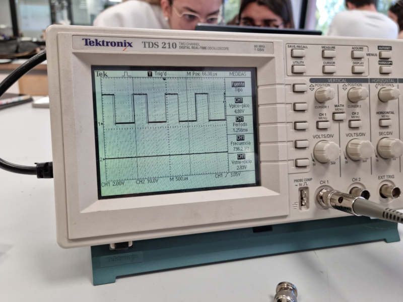
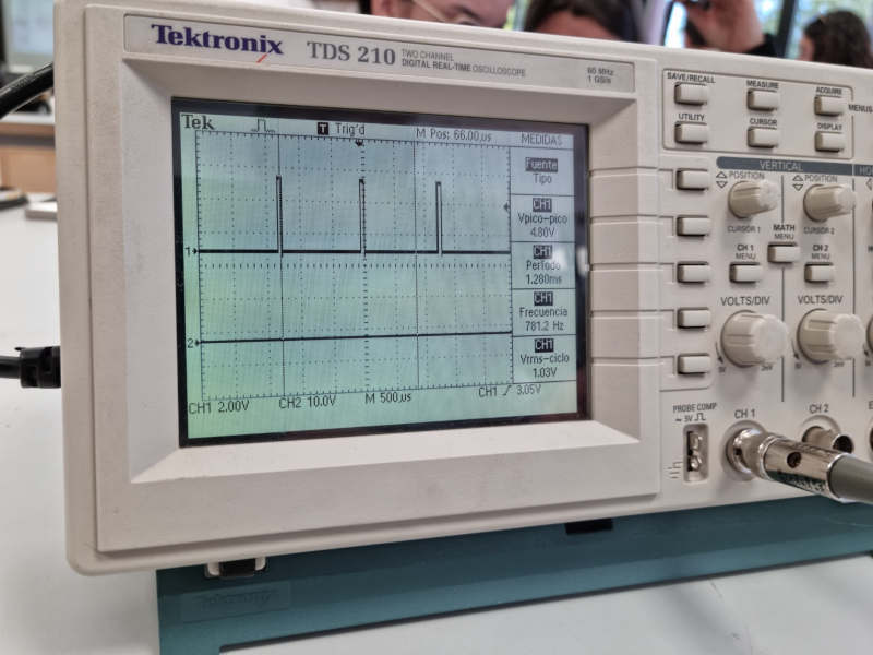
We could watch the PPM signal on the oscilloscope. The peek to peek voltage is 5V and the position of the peaks has a variation of 450 microseconds.
Individual assignment:
Measure something: add a sensor to a microcontroller board that you have designed and read it.
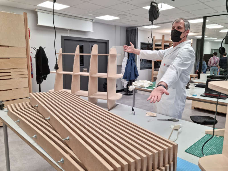
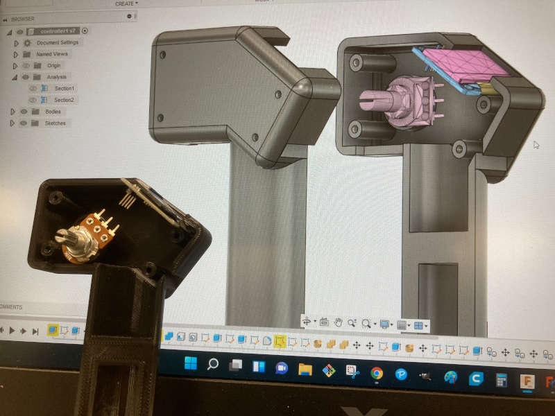
My aim is to follow making things for the final project, so I thought to make the throttle of the BLDC motors. I had to use a potentiometer as an input device, read the voltage values and convert it to a PPM signal. I will send that signal to the BLDC controller. So I will just need a MCU, an analog input and a digital output.
PWM and PPM Introduction
Source: oscarliang.com
PWM stands for Pulse Width Modulation and PPM stands for Pulse Position Modulation. PWM is a technique used to relay data in the form of a varying pulse width. In PPM (Pulse Position Modulation) the analogue sample values determine the position of a narrow pulse relative to the clocking time.
RC Devices that use PWM Pulses:
- Servos
- Electronic Speed Controllers
- R/C receivers
- Data loggers
- Autopilot/Stabilization systems
- Servo Controller
RC Devices that use PPM Pulses:
- R/C transmitters
- R/C receivers
- Autopilot/Stabilization systems
- PCTx

PWM – Pulse Width Modulation
In PWM each RC channel has it’s own cable. If we want 9 channels we must wrie all 9 cables along with the power and ground. The value of each channel is represented as a 1 millisecond (ms) to 2ms “ON” signal and this signal repeats (or updates) every 20 milliseconds. It goes high for the 1-2ms, then it falls to Low. The length of time it is high is the value for that channel. We see this in the GUI directly as 1000-2000, so we are seeing the raw ON time in microseconds.
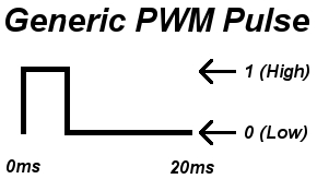
The whole frame is 20ms long, the important part of the pulse is the time the pulse is on; 1-2ms. Although the time between pulses is not as important it does play an important role. Usually keeping the time between pulses around 20ms is best. If the delay is longer, a servo for example will lose holding power. A pulse can be generated much faster but 20ms is best for most situations.
PPM – Pulse Position Modulation
Think of PPM as several PWM signals lined up back to back (not really, but that’s what it does). In PPM, the same signalling is used but each channel is sent successively, then a delay, then it loops back to channel 1.
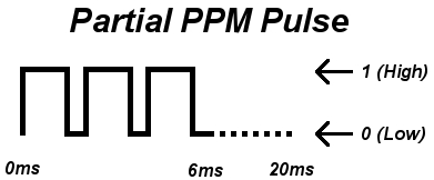
In normal PWM there are 50 updates sent per second (50Hz) which means each update takes 20 milliseconds. So if each channel takes up to 2ms, then we can do 10 channels within that 20ms before which we need to loop back to ch1. So we don’t even have a downside of multiplexing all the channels down to 1 wire and yet we have less wiring, and in our case 2 extra AUX channels! If you can do PPM, it’s better!
However PPM is not the most popular because many radios don’t support PPM. If you don’t have a PPM transmitter and receiver you can use a little device that converts between regular PWM and PPM. The MultiWii supports PPM input. Just define the appropriate option SERIAL_SUM_PPM in config.h and wire the PPM signal into the Throttle channel. The rest of the transmitter inputs like roll, pitch, and yaw are now free for other things. It is also possible to obtain PPM from PWM by using a mono-stable multivibrator circuit.
Board choice
First I thought about using one of the generic boards I made (SAMD11 and ATTiny 1614), but I realized I could do it with the most basic board, the ATtiny45 board, reusing some of the pins of the ISP connector. The board design and fabrication process can be found here.
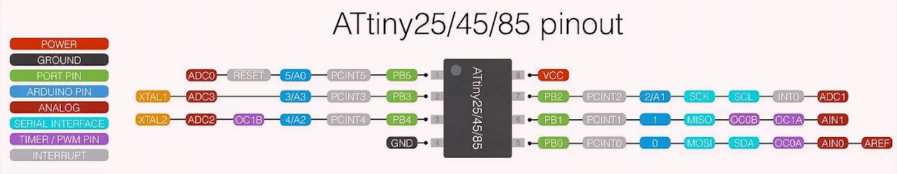
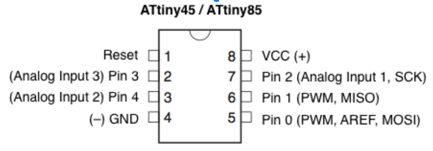
I could use pin 2 (SCK of the ISO connector) as the analog input, and pin 1 (MISO) as the PWM output. Both of them are available on the ATtiny board I made:
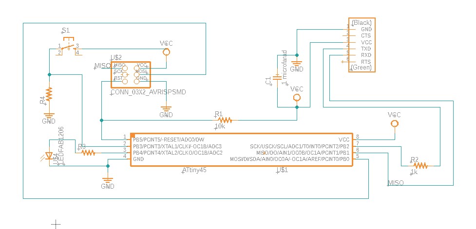
Connection schematics:
So I use the FabISP to program the ATtiny45 board with the following program:
int pwmPin = 1; // assigns pin 12 to variable pwmint pot = A1; // assigns analog input A1 to variable potint c1 = 0; // declares variable c1int c2 = 0; // declares variable c2void setup() // setup loop{pinMode(pwmPin, OUTPUT);pinMode(pot, INPUT);}void loop(){c2= analogRead(pot);c1= 1024-c2; // subtracts c2 from 1000 and saves the result in c1digitalWrite(pwmPin, HIGH);delayMicroseconds(c1);digitalWrite(pwmPin, LOW);delayMicroseconds(c2);}
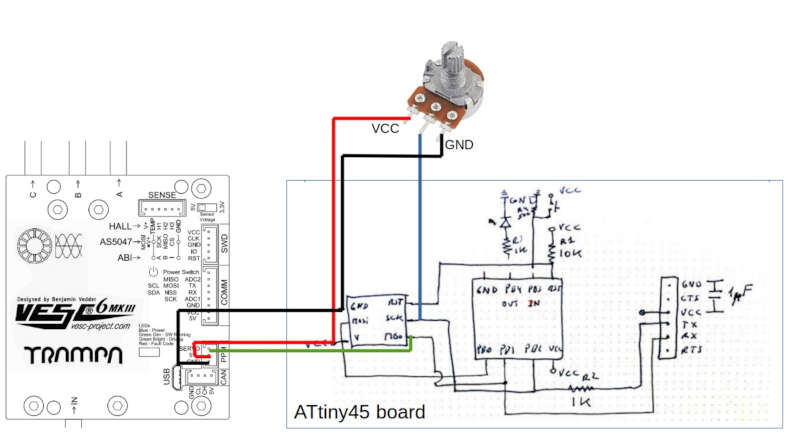
I made the connections:
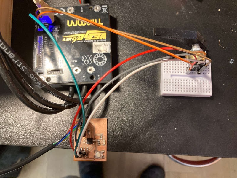
I also connected the battery and the BLDC motor to test it:
The motor controller follows very well the PPM signal generated by the ATtiny45, and it seems it a good circuit to include in my final project.
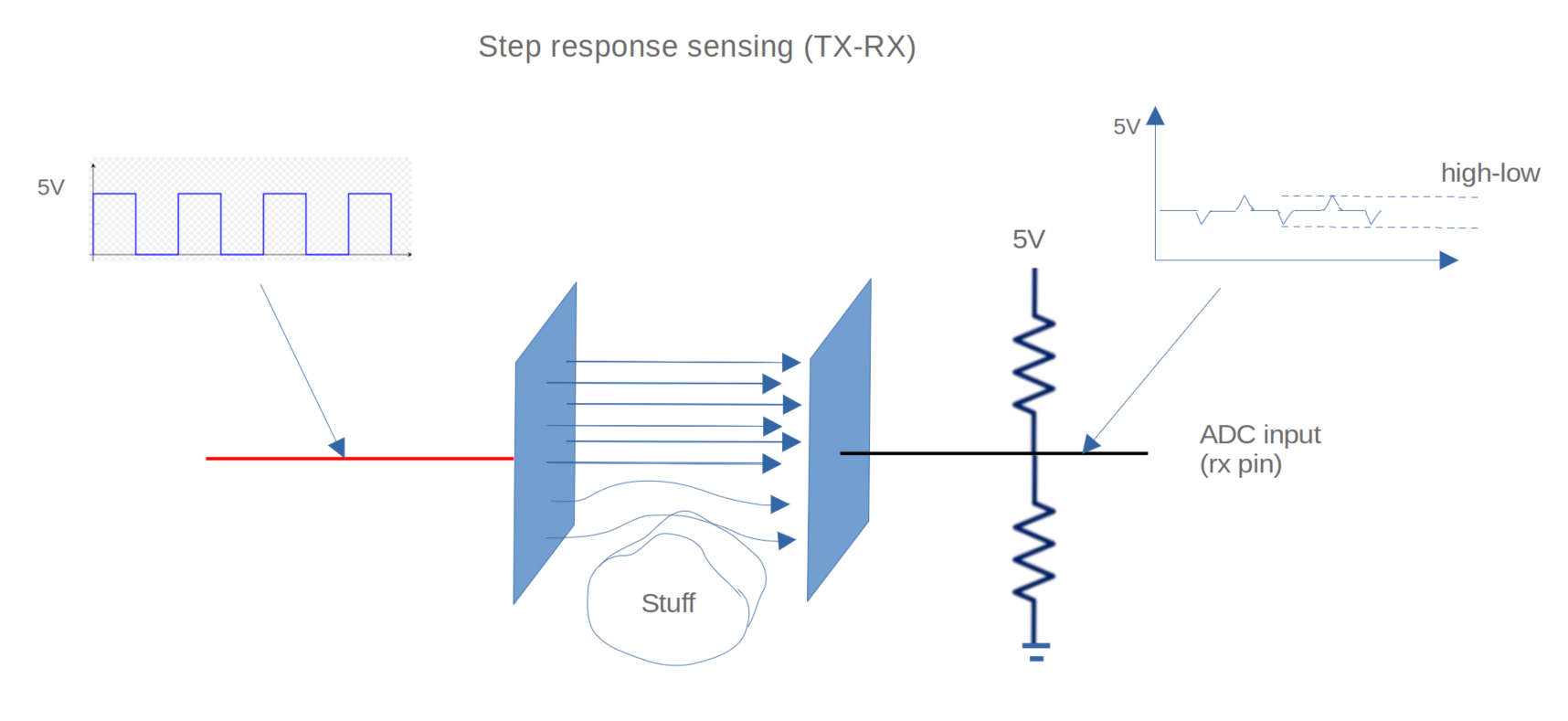
Step response
I was also interested in learning about the step response. So I learnt the concepts from the documentation of Robert´s Hart, and Neil´s Gershenfeld documentation.
We inject a square signal on the TX electrode and we get some peaks of the signal on the RX electrode. Depending on the coupling of the TX-RX electrodes the amplitude of the peaks vary.
To isolate the system from the variation of the electromagnetic field due to external noise we don't measure the absolute height of the peaks, but the difference between the high and low peaks.
The distance of the electrodes and the material between them changes the coupling an the amplitude of the peaks at the rx signal, we can measure it and map with the physical magnitude we want to measure.
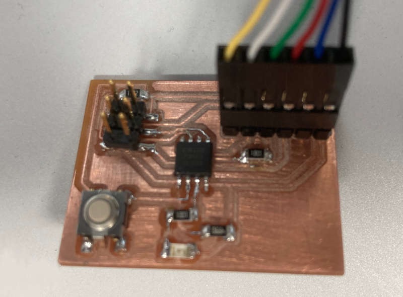
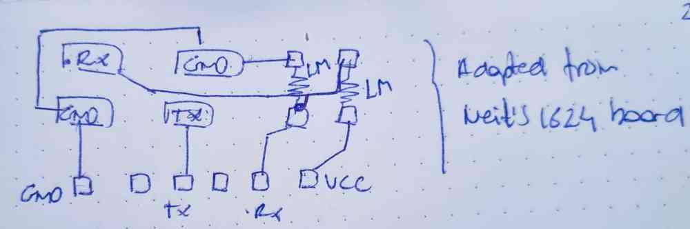
As mi fabmate Pedro Chana was going to make a board to try step response, we decided to make two boards, so I could also make it. This is the board (design by Pedro):
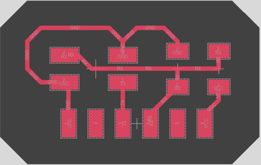


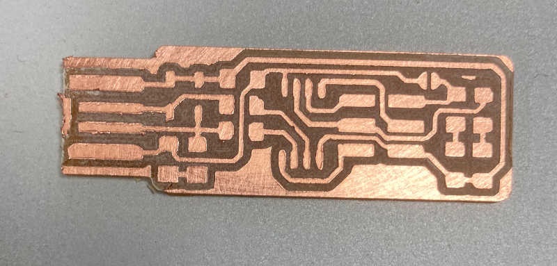
Step Response traces and outline
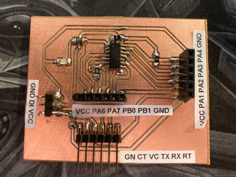
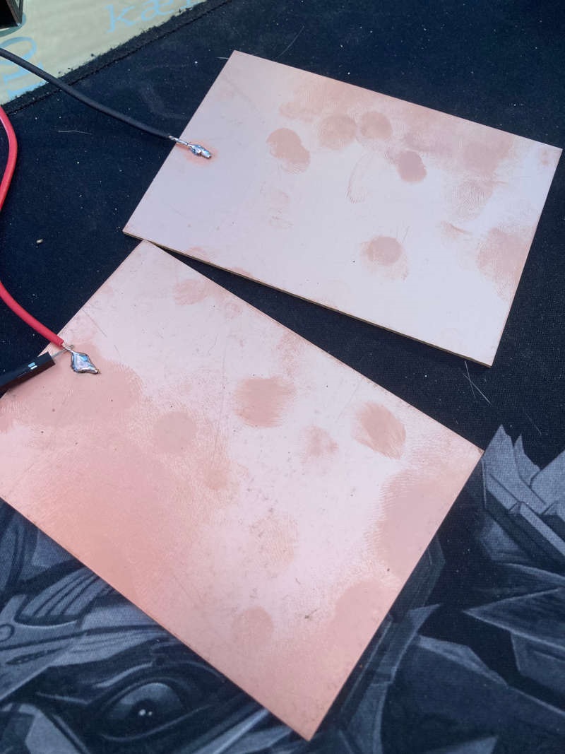
I also used my Attiny1614 generic board (details here) and two PCB boards as the step response electrodes:
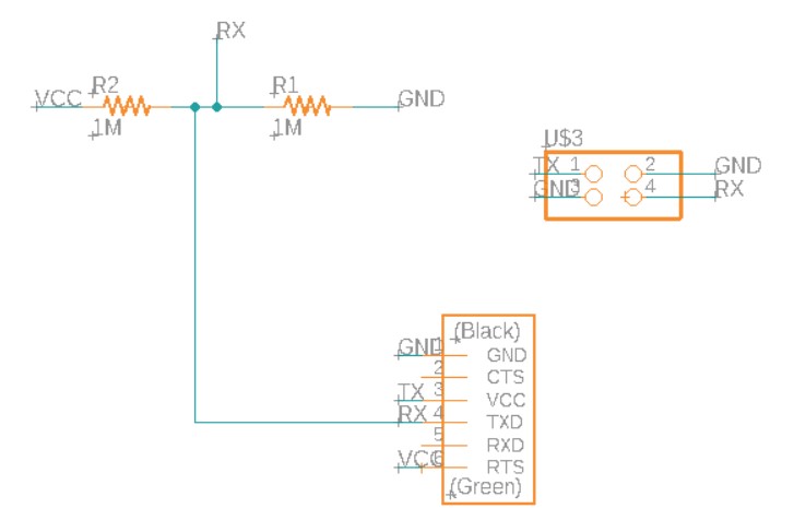
This is the connection diagram:
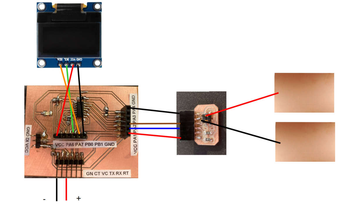
This is the code I used. The tx_rx function injects high and low voltages on the tx output and reads the high and low values on the rx input. It adds N samples and returns the result. The loop is all the time calling that function and displaying the result on the OLED display.
//tx_rx03  From Robert Hart Mar 2019
//https://roberthart56.github.io/SCFAB/SC_lab/Sensors/tx_rx_sensors/index.html

//Modified from Adrián´s Adrianino´s step response 2021: https://fabacademy.org/2020/labs/leon/students/adrian-torres/adrianino.html#step

//Adapted by Jon Merino 2022
//Pin changes.
//Added digitalWriteFast.
//Added Oled screen output.

#include <Wire.h>
#include <Adafruit_GFX.h>
#include <Adafruit_SSD1306.h>

#define SCREEN_WIDTH 128 // OLED display width, in pixels
#define SCREEN_HEIGHT 64 // OLED display height, in pixels

// Declaration for an SSD1306 display connected to I2C (SDA, SCL pins)
Adafruit_SSD1306 display(SCREEN_WIDTH, SCREEN_HEIGHT, &Wire, -1);


long result;   //variable for the result of the tx_rx measurement.
int analog_pin = A2; //  PA2 of the ATtiny1614
int tx_pin = A1;  //     PA1 of the ATtiny1614
void setup() {
pinMode(tx_pin,OUTPUT);      //Pin 2 provides the voltage step
Serial.begin(115200);
  if(!display.begin(SSD1306_SWITCHCAPVCC, 0x3C)) {
    Serial.println(F("SSD1306 allocation failed"));
    for(;;); }
  delay(2000);
  display.clearDisplay();
  display.setTextColor(WHITE);}

long tx_rx(){         //Function to execute rx_tx algorithm and return a value
                      //that depends on coupling of two electrodes.
                      //Value returned is a long integer.
  int read_high;
  int read_low;
  int diff;
  long int sum;
  int N_samples = 100;    //Number of samples to take.  Larger number slows it down, but reduces scatter.

  sum = 0;

  for (int i = 0; i < N_samples; i++){
   digitalWriteFast(tx_pin,HIGH);              //Step the voltage high on conductor 1.
   read_high = analogRead(analog_pin);        //Measure response of conductor 2.
   delayMicroseconds(100);            //Delay to reach steady state.
   digitalWriteFast(tx_pin,LOW);               //Step the voltage to zero on conductor 1.
   read_low = analogRead(analog_pin);         //Measure response of conductor 2.
   diff = read_high - read_low;       //desired answer is the difference between high and low.
 sum += diff;                       //Sums up N_samples of these measurements.
 }
  return sum;
}                         //End of tx_rx function.

void loop() {

result = tx_rx();
result = map(result, 19000, 50000, 0, 1024);  //I recommend mapping the values of the two copper plates, it will depend on their size
Serial.println(result);
delay(100);
delay(100);
   //clear display
  display.clearDisplay();
  // display
  display.setTextSize(1);
  display.setCursor(0,0);
  display.print("Strenght:");
  display.setTextSize(2);
  display.setCursor(0,10);
  display.print(result);
  display.print("");

  display.display();
}
And the final test:
It measures the proximity of the hand, because the hand alters the electromagnetic field around the electrodes. It's a very sensitive and accurate way of measuring it.
As you can see, it works pretty well with 2 PCB boards acting as electrodes, better than the conductive vinyl, because it is more stable an robust. Watching the results and comparing our two step responses my classmate Pedro Chana decided to include PCB boad cut pieces in his final project.