Final project development: Skit

Table of Contents
- What's the project?
- Tasks completed: making process
- The survey
- Electric motors research
- Looking for BLDC motors
- VESC, the opensource project for motor control
- The caterpillar
- First Designs
- First thoughts about electronics
- The 3D printed controller
- Electronics
- The boards
- The ski press
- Ski core
- The ski sole and edges
- Planning
- Ski composite making
- The caterpillar
- The heat wave
- The second caterpillar: MDF wood
- Third caterpillar. Version 2.0 with some improvements and HDPE
- System integration
- What tasks remain?
- What has worked? What hasn't?
- What questions need to be resolved?
- What will happen when?
- What have you learnt?
- Files
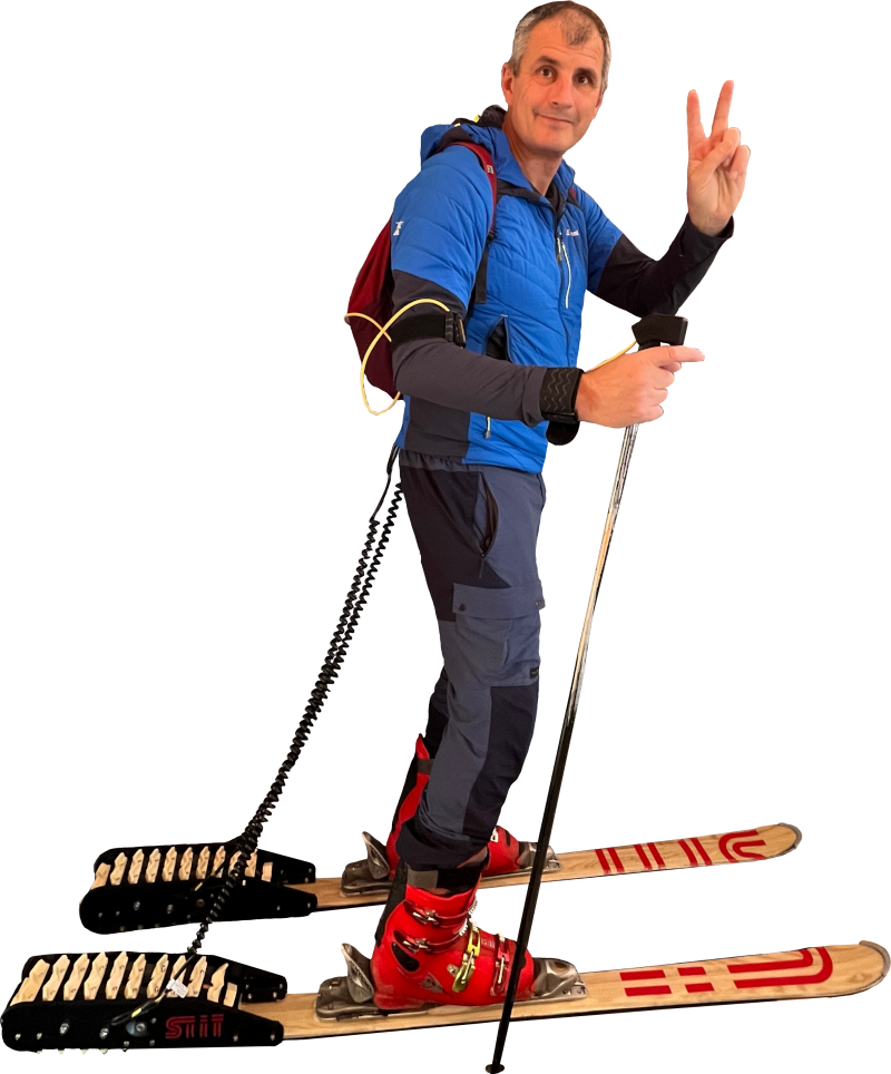
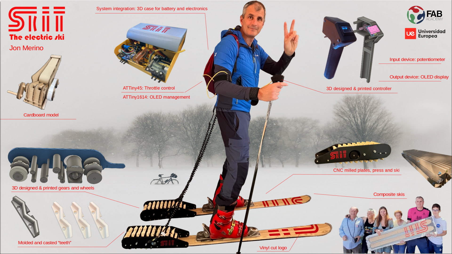
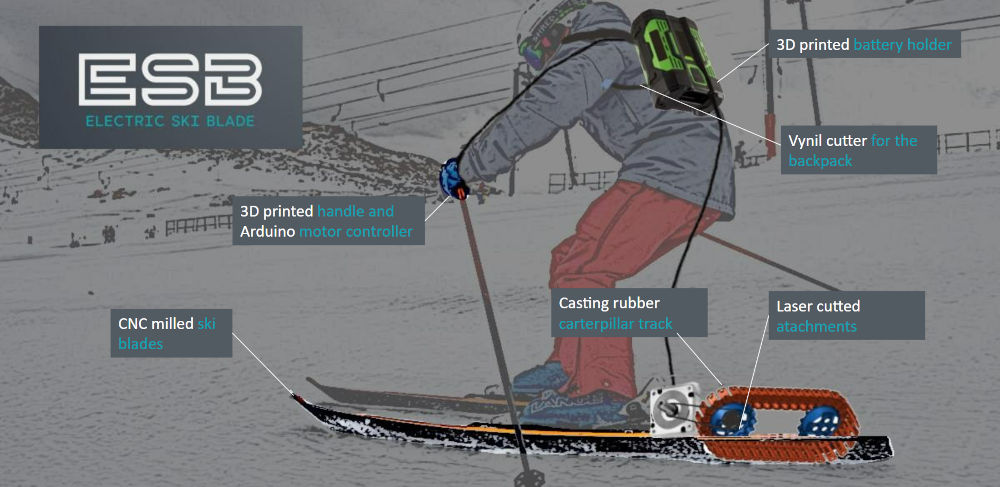
What's the project?
My final project is Skit, an electric ski. So, basically a ski with an electric motor, a caterpillar, a battery and a controller. The ultimate and utopic goal would be to go uphill without a chairlift, so we wouldn't need to fill ours mountains with chairlifts. Also it can be very useful just to go from one place to another.
Tasks completed: making process
The survey
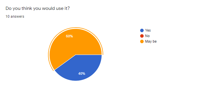
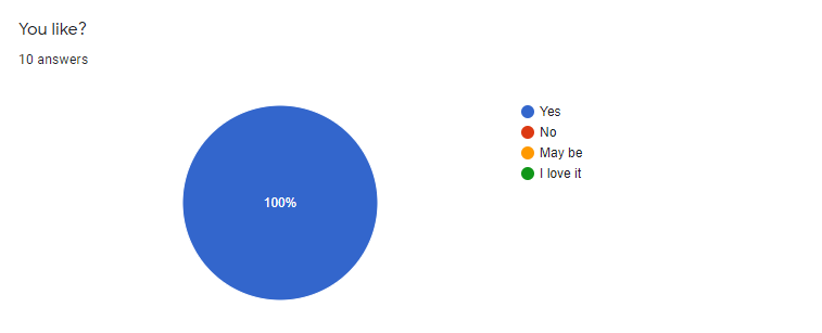
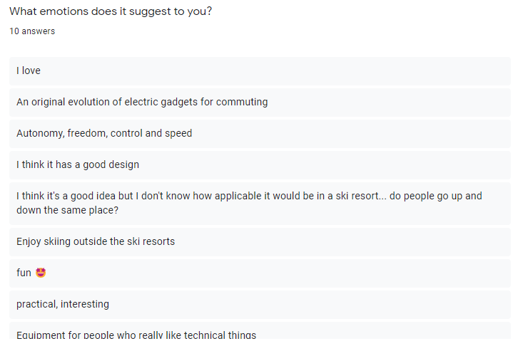
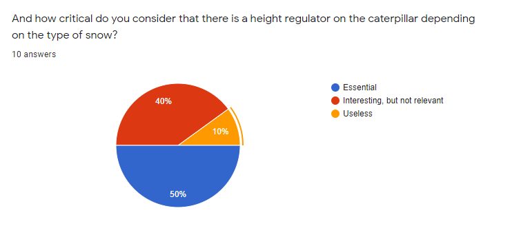
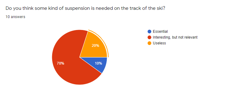
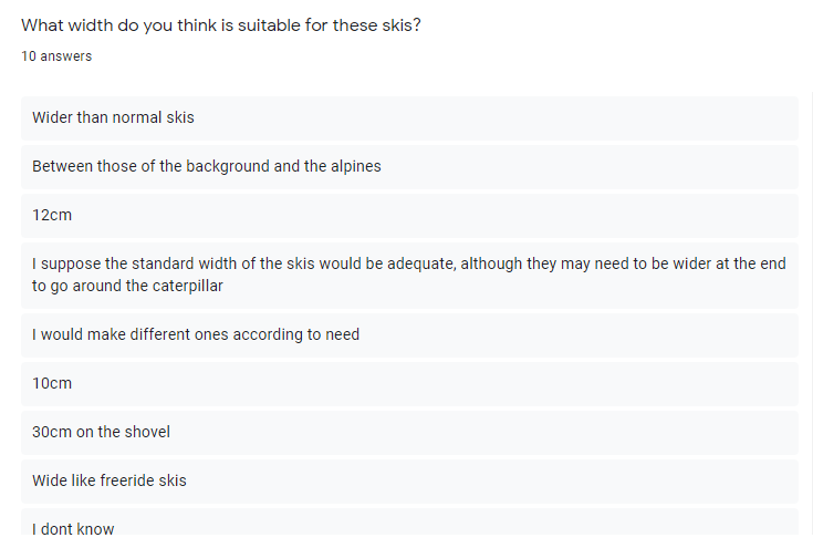
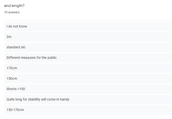
As I mentioned in the first week assignment, during the design thinking process I had a lot of questions to answer, so I made a questionnaire to get some feedback from potential users of Skit. They were several amateur skiers, two semi-pro skiers and some engineers and scientist. These are the results:
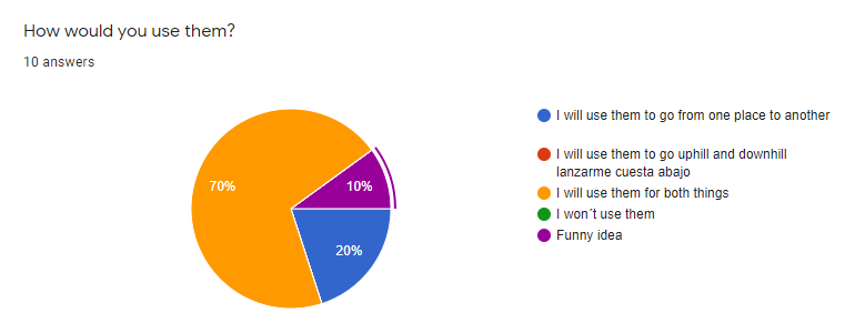
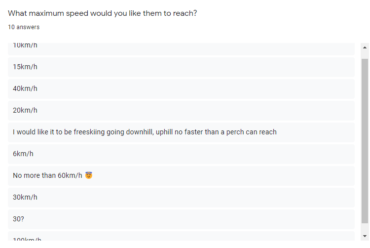
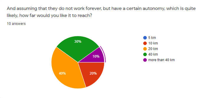
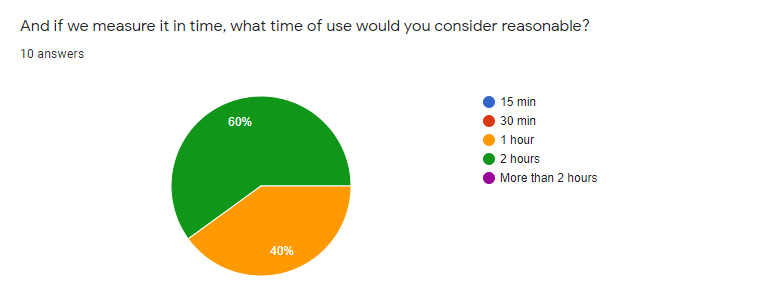
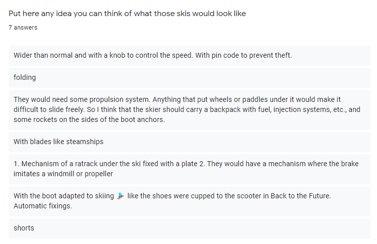
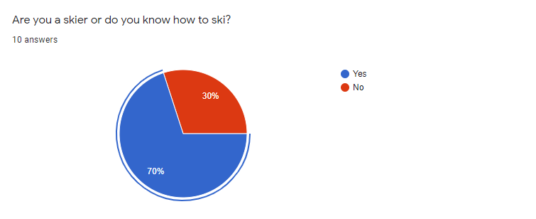
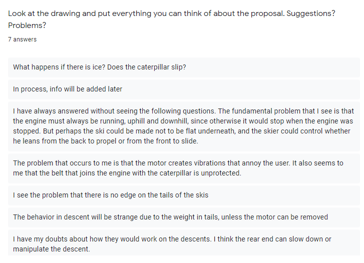
So, according to the answers of the potential user, Skit could have the following features:
- If possible, It can be used to travel for one place to another, but also to go uphill and downhill.
- Around 20 km of range, 1-2 hours autonomy.
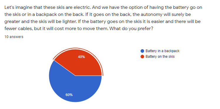
- The battery would be in a backpack
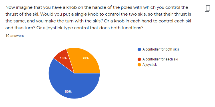
- Same controller for both skis, a joystick to turn have to be studied.
- A height regulator for the caterpillar
- They could be wider than conventional skis
- I could include a curved edge on the tail, so the carving function keeps working.
Electric motors research
I have been analyzing the different types of electric motors available, mostly the ones that are used in electric bikes and scooters. And there are two main types of them: brushed and brushless motors.
The most simple form of an electric motor is a brushed DC motor where two brushes are used for power transmission and commutation. The disadvantage is the fact that the brushes burn down and need to be replaced regularly.
In a BLDC = brushless DC motor the commutation is done electronically and the motors most often have three phases which sit at an angle of 120°
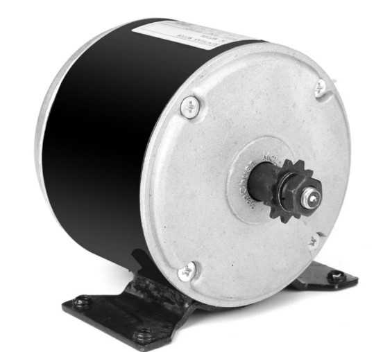

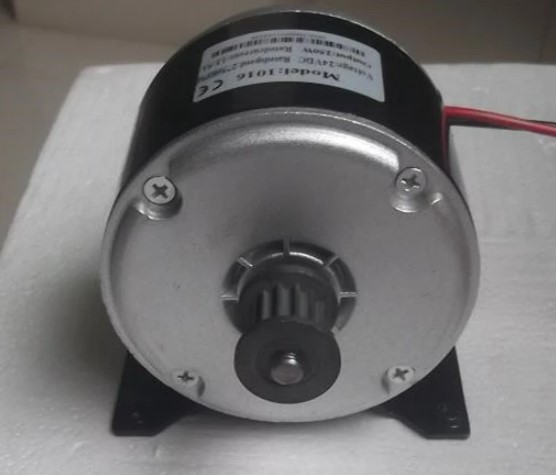
Different types of brushed motors, of 24V 350W, 36V 500W and 24V 250W. Their weight is around 2kg and the radius around 10 cm.
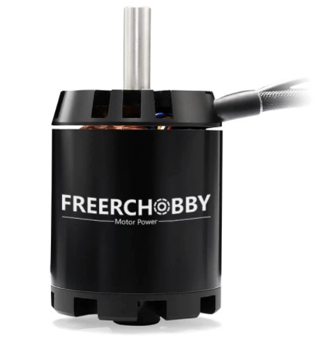
Some brushless motors, up to 3.500W depending on voltage, weight around 1kg and radius around 6 cm.
So brushless motors are more powerful and compact. On the other hand, the control is more difficult and they are more expensive.
In our case, the size and weigh of the motor is critical, because you have to move the skis, and they have to be as light as possible. Also, if you want to use them to go uphill, you will need as much power as possible in a compact sized motor. There is no doubt brussless motors (BLDC) are the best for Skit.
In addition, with that compact size, the motor can be placed inside the caterpillar. It would be a more compact and clean design, and there won't be pieces outside the profile of the ski.
Looking for BLDC motors
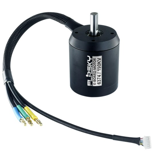
I started looking for suitable BLDC motors for Skit. There are some of them oriented to electric bikes, and some others oriented to electric skateboards and scooters. This seem to be the best for my project, because they are very compact an powerful. There are also dual motors for electric longboards (one for each rear wheel), and this is perfect for me, as I need one motor for each ski blade. This could be a good one:
6384 brushless dc motor 24v, 36v 48v for E boards skateboard
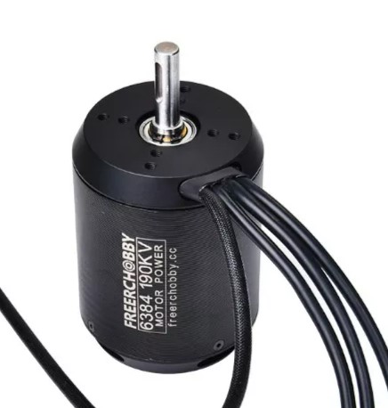
Specs:
Max Power: 4000 Watts
Max Current: 100Amps
Max Volts: 12S
Max Torque: 9Nm
Motor Resistance: 0.05Ohm
Recommend ESC: 3-12S 100A
Weight: 1 kg
The motor length:84mm
The motor diameter: 63mm
SHAFT: Diameter 10mm with keyway slot.
- Motor Wire: 130mm silicone 12AWG wire with 4.0mm Gold Bullet Connector Male.
- Wire configuration:
Blue = A
Black = B
Yellow = C
Stator: 0.2mm thickness lamination japan steel
Magnet: N42SH high temp curve magnet
BLDC Motor
The number of pole: 14
One interesting feature of Flypsky's motors and controllers is that they are "VESC compatible". ¿And what is VESC? A very interesting opensource project:
VESC, the opensource project for motor control
Aim of Vesc: Our aim is simply providing the best and most professional open source firmware, user friendly software solutions and hardware for motor control available today.
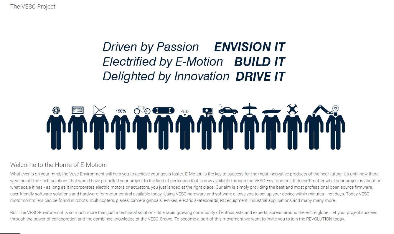
It's worth it to have a look at the project. Perhaps I can use part of the software/hardware, adapt it to my ski project and maybe to collaborate with the Vesc project adding new functionality.
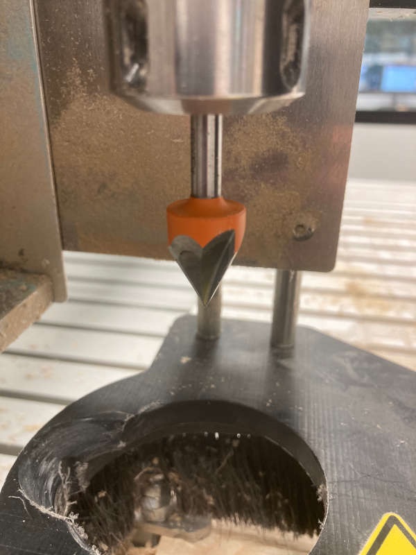
The caterpillar
It is probably the most critical part of the design (always movable parts are), because it supports all the tensions and traction of the system. There are lots of examples of doing caterpillars in the web:
https://www.youtube.com/watch?v=uosV8NLo1iY
First Designs
First thoughts about electronics
The power applied to the motor can be controlled by varying the width of these applied pulses and thereby varying the average DC voltage applied to the motors terminals. By changing or modulating the timing of these pulses the speed of the motor can be controlled, ie, the longer the pulse is “ON”, the faster the motor will rotate and likewise, the shorter the pulse is “ON” the slower the motor will rotate.

(from https://www.electronics-tutorials.ws/blog/pulse-width-modulation.html)
Another advantage is that PWM can be easily generate with a microcontroller.
The 3D printed controller
I started modelling the controller handle. It has two functions: to manage the throttle and to show status and some data of the skis. So it has a potentiometer and a display. I begin with some components I saw in the lab: the AZdelivery OLED display and an standard potentiometer.
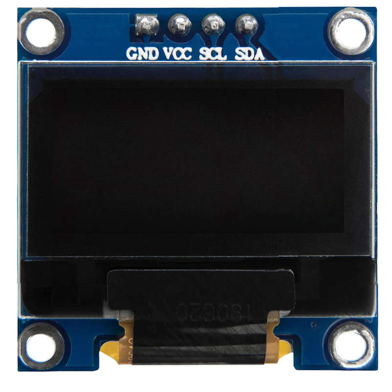
The AZDelivery OLED display
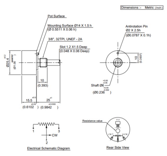
A standard potentiometer
So I sketched a controller:
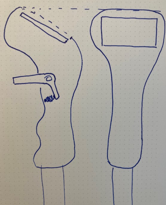
I began to model a parametric design of the controller on Fusion360:
The detail of the 3D modelling can be seen on week 5: 3D scanning and printing.
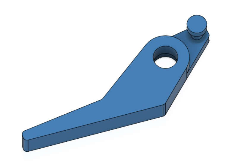
I also modeled a "trigger" for the potentiometer and added a springy:
Electronics
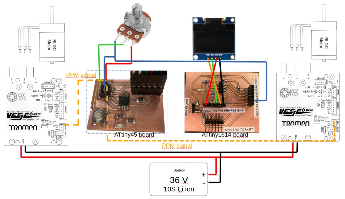
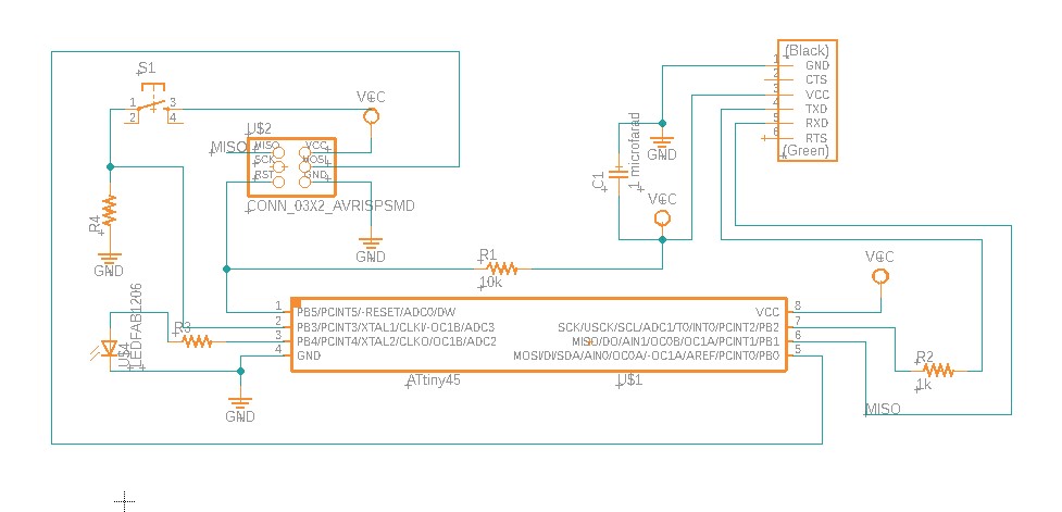
I use an ATtiny45 board and an ATtiny1614 board. The ATtiny45 converts the potentiometer voltage into a PPM signal to drive the BLDC controllers. The Attiny1614 manages the display, showing when the system is on and showing a graphic of the throttle.
Note: BDLC controllers are commercial, based on the VESC project open hardware (Trampa boards MK6 controllers).
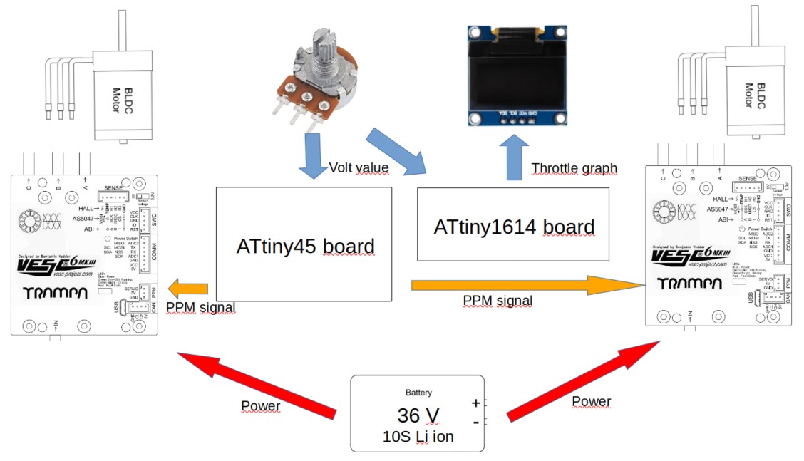
A more detailed schematics:
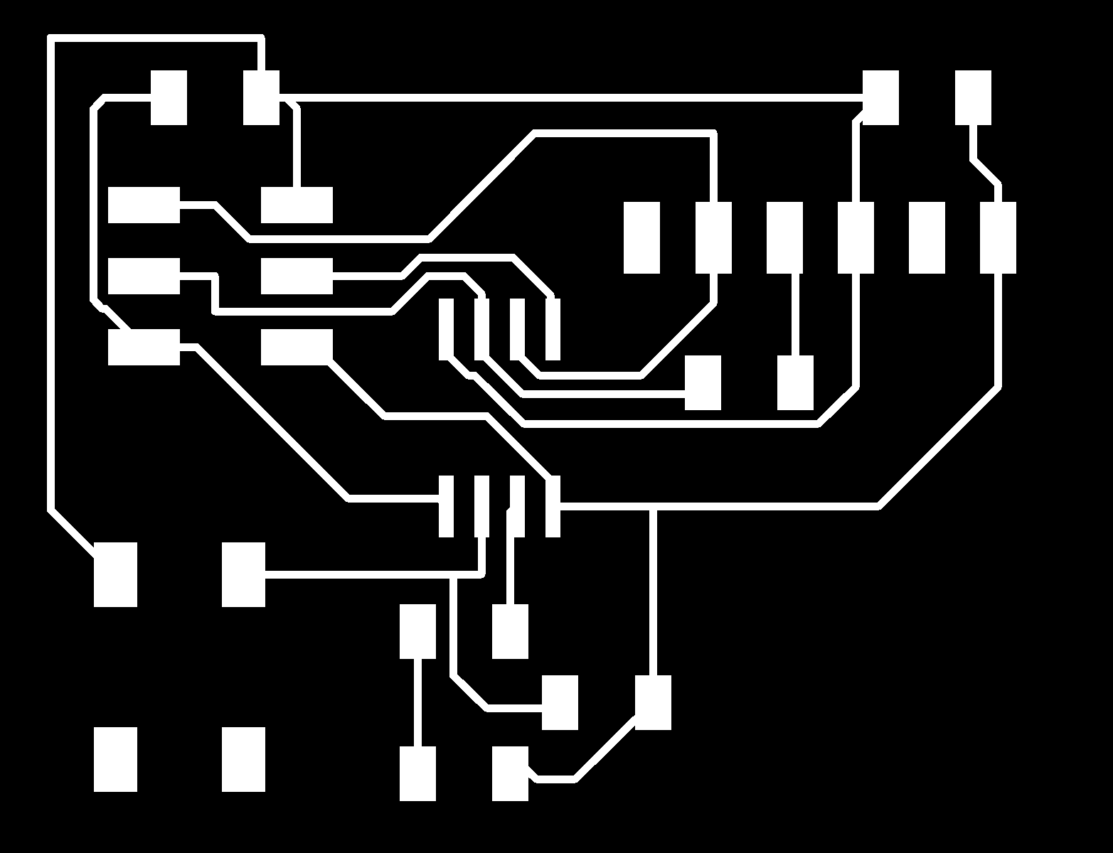
The boards
ATtiny 45 board
I used a very simple ATtiny 45 board to manage the throttle generating a PPM signal from the potentiometer voltage, using the pins of the ISP interface once it is programmed.
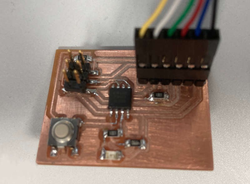
I tried to make a compact circuit, so it can be easily placed anywhere:
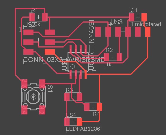

And this is the final result of the board:
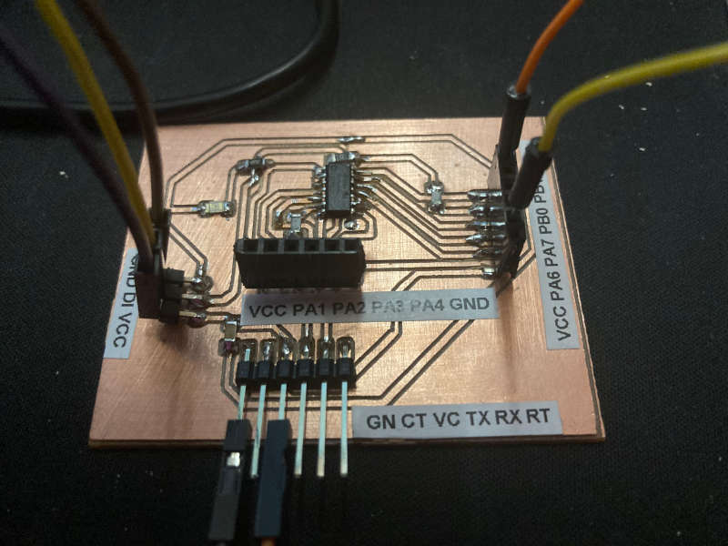
ATtiny 1614 board
I used the ATtiny1614 board I made on week 10, more details can be found there.
The board has almost all the pins of the MCU available, along with FTDI and UPDI interfaces.
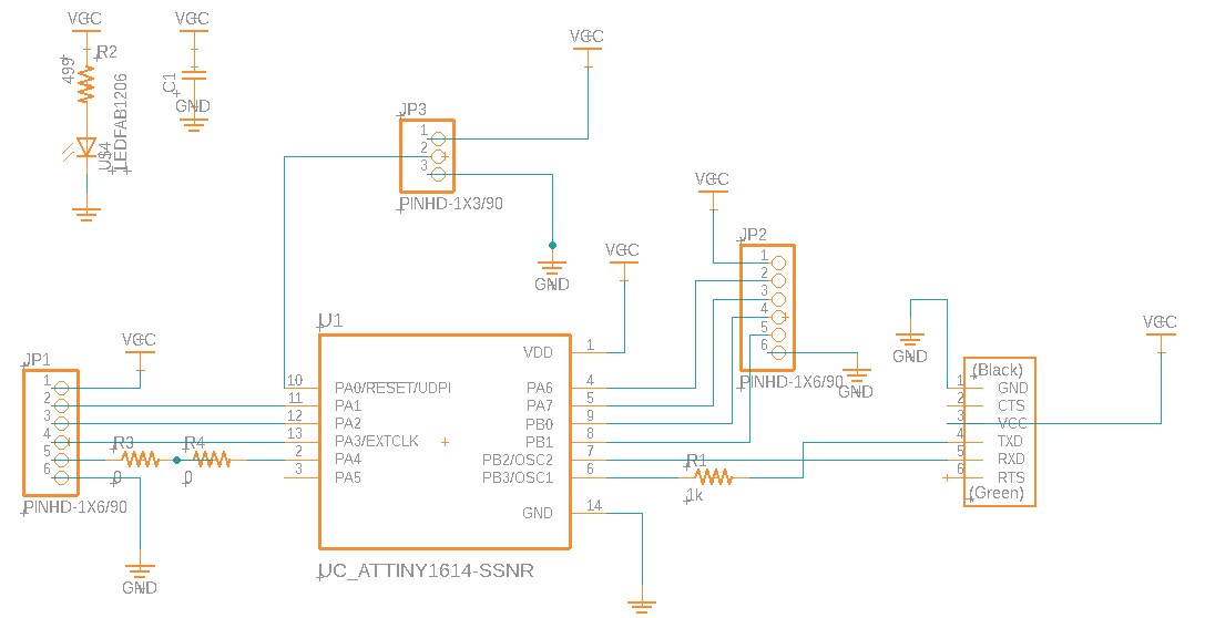
The MCU is on the center of the board and GND is around the board, I like to design the boards that way.
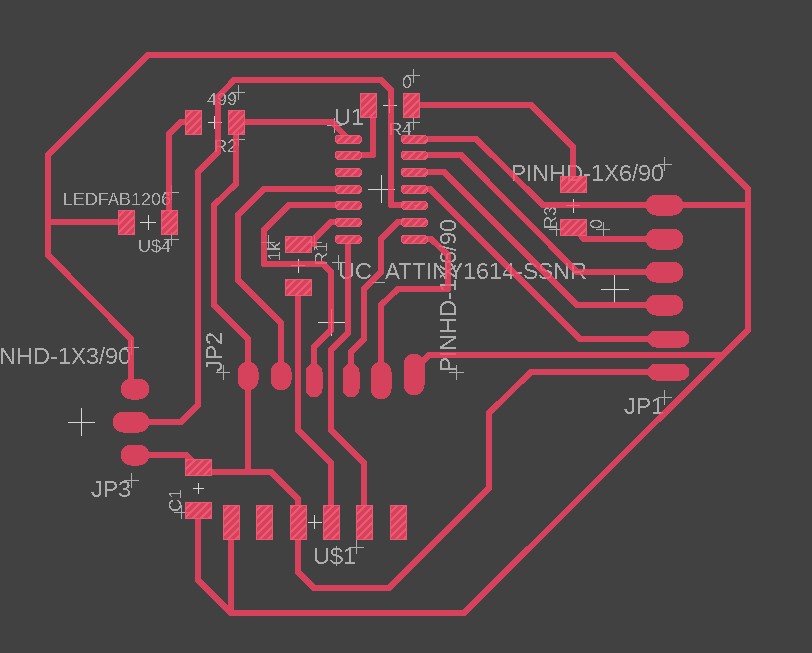
This is the png image to mill the board:
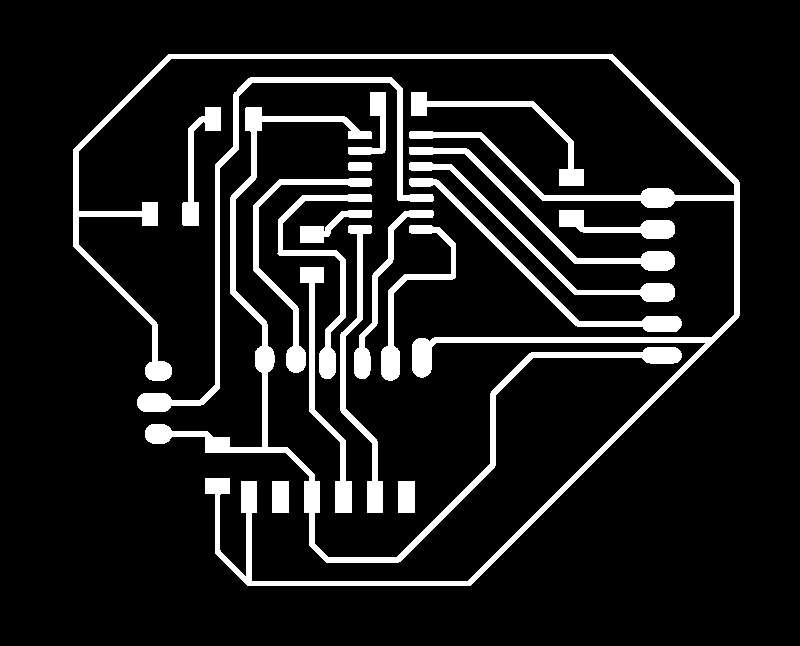
And the final result:
The code for the ATtiny45 board
It reads the value of the potentiometer and generates 2 PPM signals, one for each of the BLDC controllers.
int pwmPin1 = 0;int pwmPin2 = 1;int pot = A1; // assigns analog input A1 to variable potint c1 = 0; // declares variable c1int c2 = 0; // declares variable c2//int min=108;//int max=139;void setup() // setup loop{pinMode(pwmPin1, OUTPUT);pinMode(pwmPin2, OUTPUT);pinMode(pot, INPUT);}void loop(){// c2= map(analogRead(pot), min, max, 0,1000);c2=analogRead(pot);c1= 1000-c2; // subtracts c2 from 1000 ans saves the result in c1digitalWrite(pwmPin1, HIGH);digitalWrite(pwmPin2, HIGH);delayMicroseconds(c1);digitalWrite(pwmPin1, LOW);digitalWrite(pwmPin2, LOW);delayMicroseconds(c2);}
The code for the ATtiny1614 board
It shows an "ON" message on the display and draws a progression bar of the throttle.
#include <Wire.h>#include <Adafruit_GFX.h>#include <Adafruit_SSD1306.h>#define SCREEN_WIDTH 128 // OLED display width, in pixels#define SCREEN_HEIGHT 64 // OLED display height, in pixels// Declaration for an SSD1306 display connected to I2C (SDA, SCL pins)Adafruit_SSD1306 display(SCREEN_WIDTH, SCREEN_HEIGHT, &Wire, -1);int pot=8; //assgning input to 8 (PA1)int volt=0;int min=432;int max=558;int reach;int squares;int i;void setup() {pinMode(pot, INPUT);if(!display.begin(SSD1306_SWITCHCAPVCC, 0x3C)) { // Address 0x3C for 128x64for(;;);}delay(2000);// Display static text//display.println("Skit ready");// display.display();//delay (2000);}void loop() {volt= 1024-analogRead(pot);reach= map (volt,min, max, 0,128);squares=reach/8;display.clearDisplay();display.setTextSize(2);display.setCursor(0,0);display.println("Skit ON");//display.setCursor(0,10);//display.print("voltaje:");//display.setTextSize(2);//display.setCursor(0,20);//display.print(volt);//display.print("");for (i=0;i<=squares;i++){display.fillRoundRect(i*8, 60-i*2, 7, 5+i*2, 2, WHITE);}display.display();}
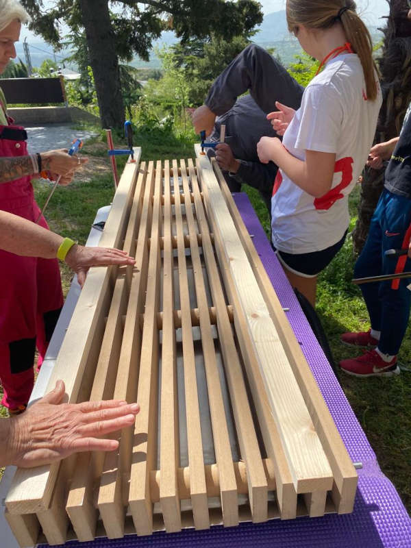
The ski press
As it is detailed on the week 7 (Computer controlled machining), a ski consist of a sandwich of different layers:
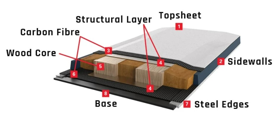
So I made a ski press with the CNC, in order to use it to cast and cure all this layers and give them the profile of the ski.
Details and files of the press making can be found at Week 7: Computer Controlled Machining
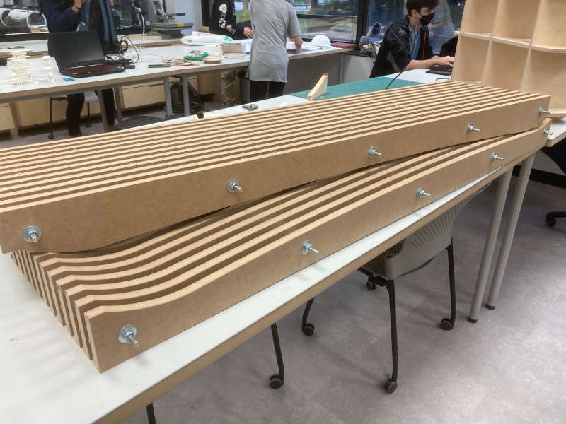
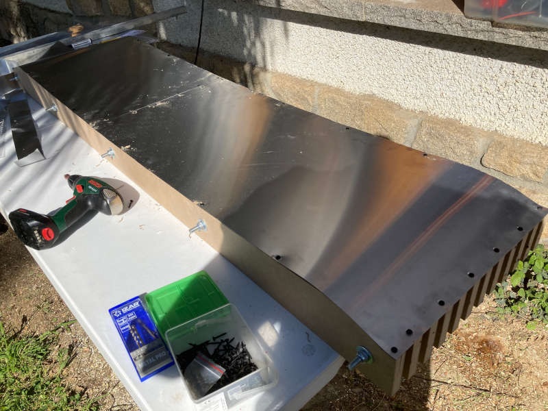
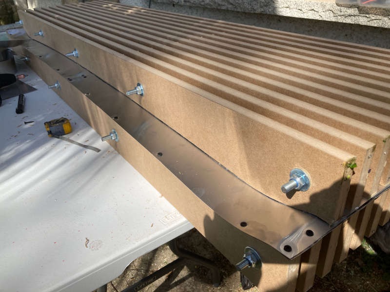
I put a steel sheet on top of both sides of the press to make a flat surface:

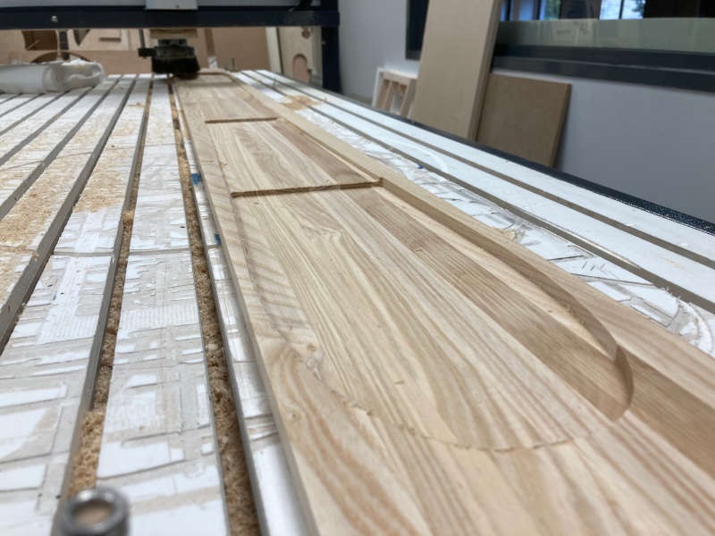
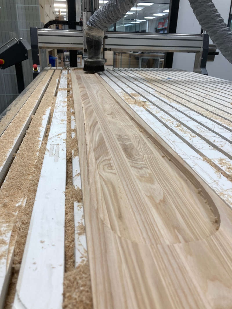
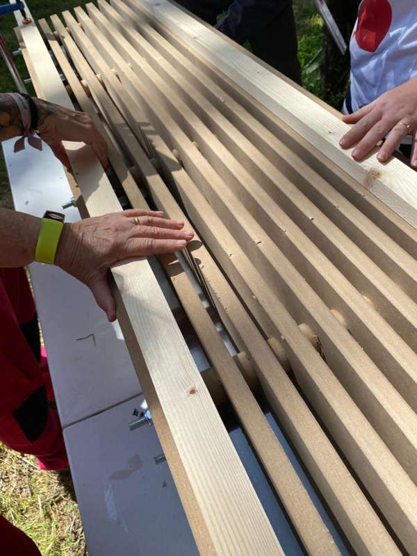
Ski core
The ski core is made of laminated wood, so I generated the ski model using a specific opensourse program (snow-cad) to get the profile of the ski. Combining the front and top profiles on Fusion 360 I got the 3D model and milled it on the CNC machine:
Details of the process and files can be found at Wildcard week. Composite ski making
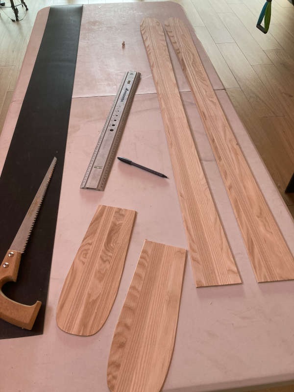
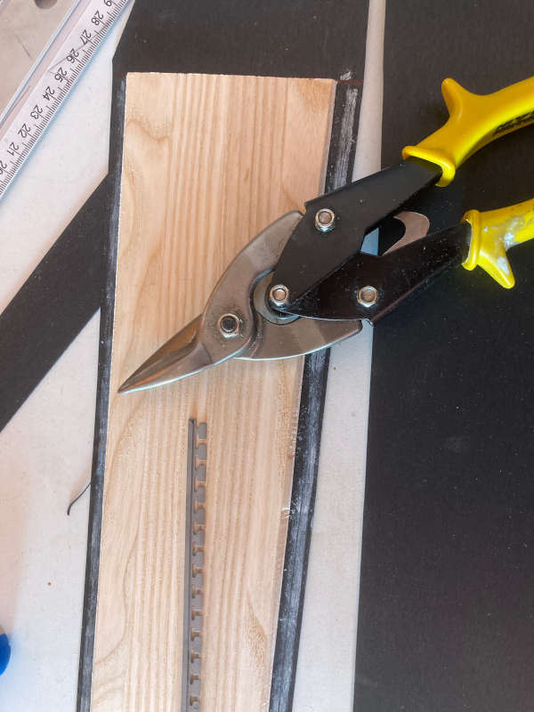
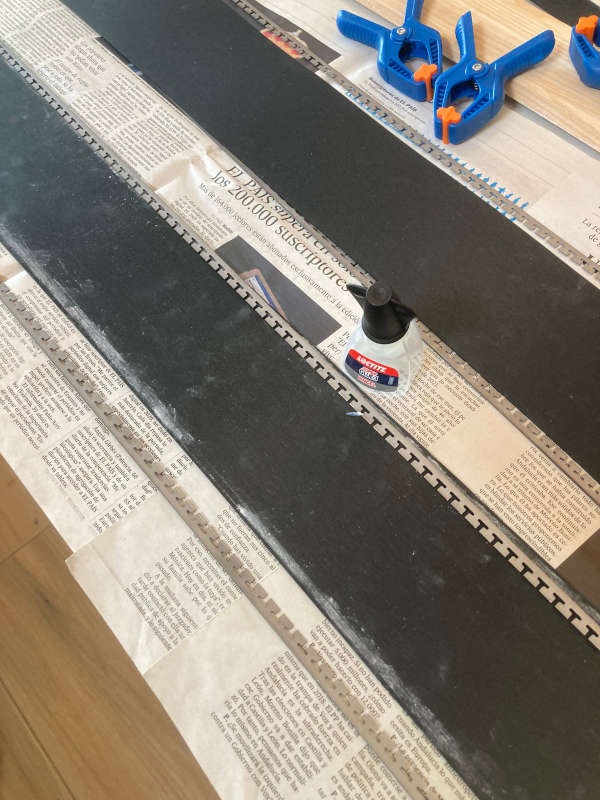
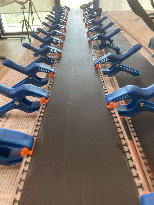
The ski sole and edges
To allow the ski to slide properly the sole is made of PTEG plastic. And to have the carving effect (to turn when you push and bend the ski) it has to got steel edges on the sole. So you have to cut a PTEG sheet with the ski shape and glue the steel edges to it:
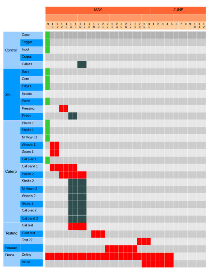
Planning
On May 10th I made a planning for the remaining tasks of the final project:
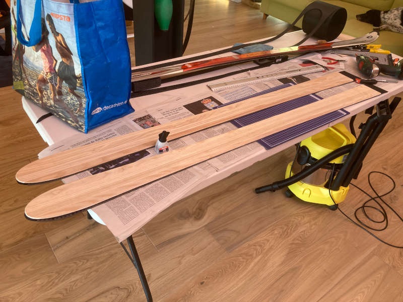
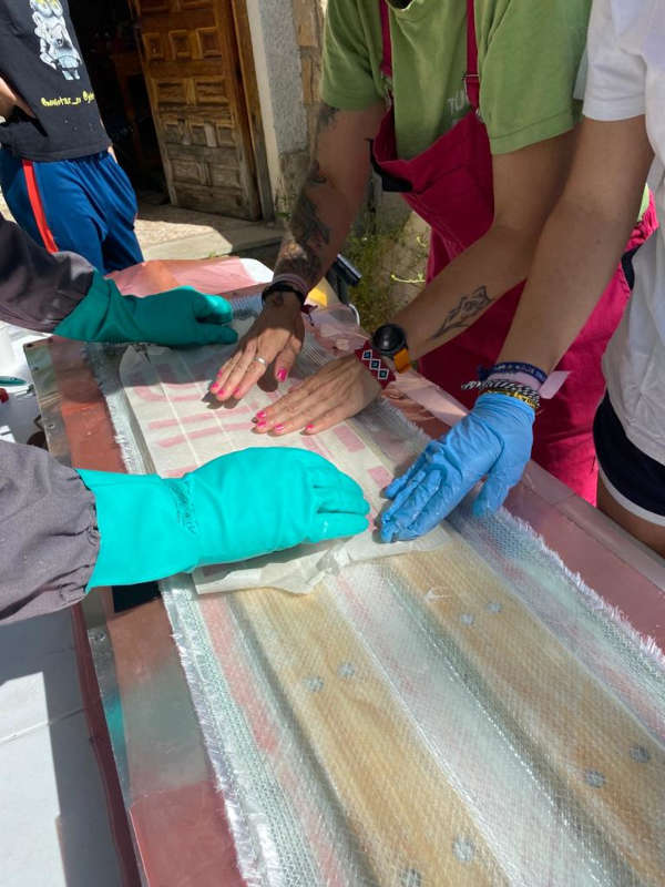
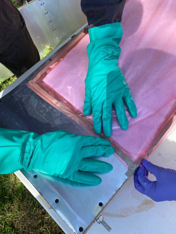
Ski composite making
On may 15th I made the composite making of the skis, as it is detailed on week 15.
the list of tasks was:
1-To put the bottom of the vacuum plastic bag on the press.
2-To put the PTEG black base on it.
3-To mix the Epoxy resin. Clock starts counting 45 minutes (work time of the epoxy)
4-To apply a first layer of epoxy resin
5-To put the first fiberglass sheet
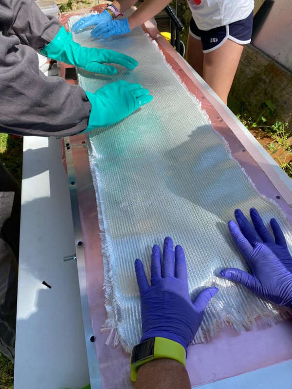
6-To apply a layer of epoxy resin on the fiberglass, until it is transparent.
7-To put the wood core of the skis, adjusting it to the base.
8-To apply another layer of epoxy.

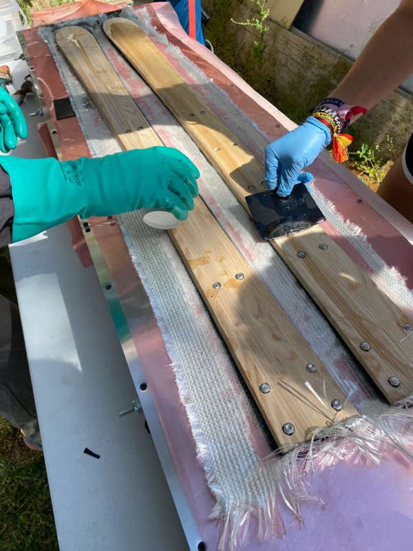
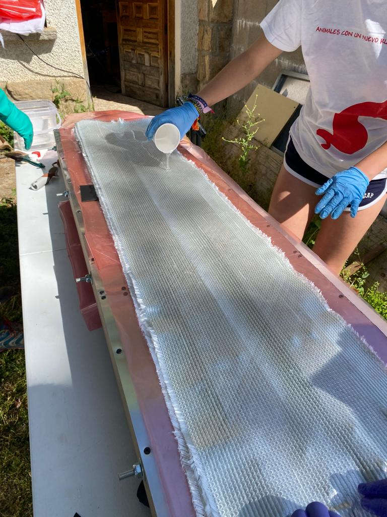
9-To put the second fiberglass sheet.
10-Epoxy again until it is transparent
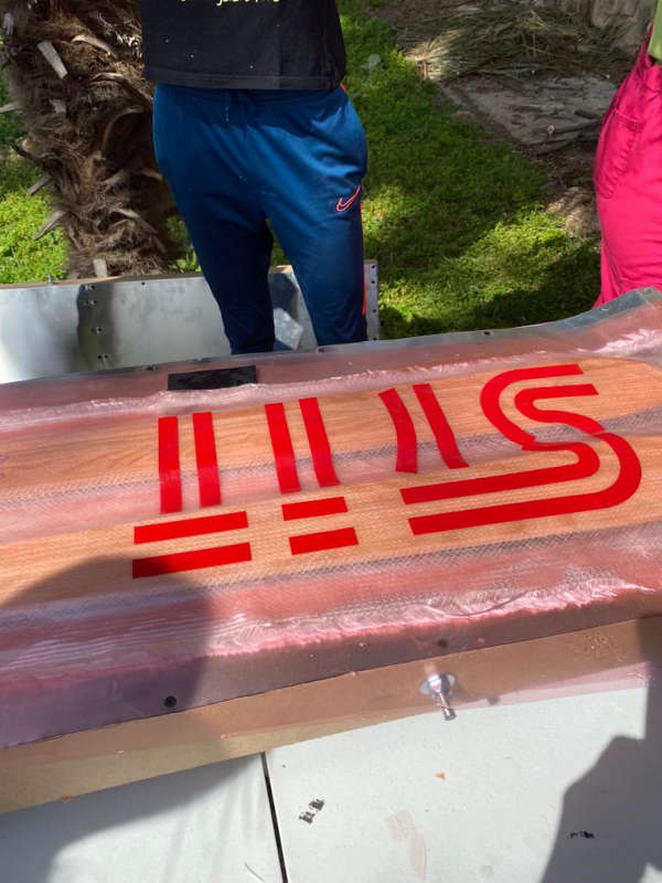
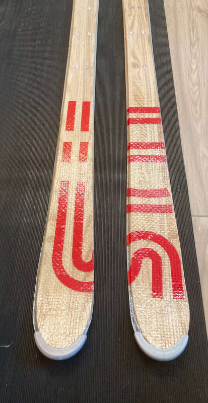
11-The vinyl logo. This was a mistake, because trying to put the vinyl logo on the epoxy was very difficult. It would have been much better to put it on the wooden core. I thought the epoxy resin wasn't going to be so transparent. Because of that I decided to put it on the top. But once I saw the final result, it's clear that it would have been better the other way.
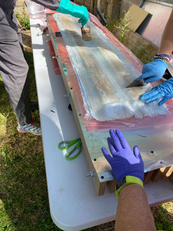
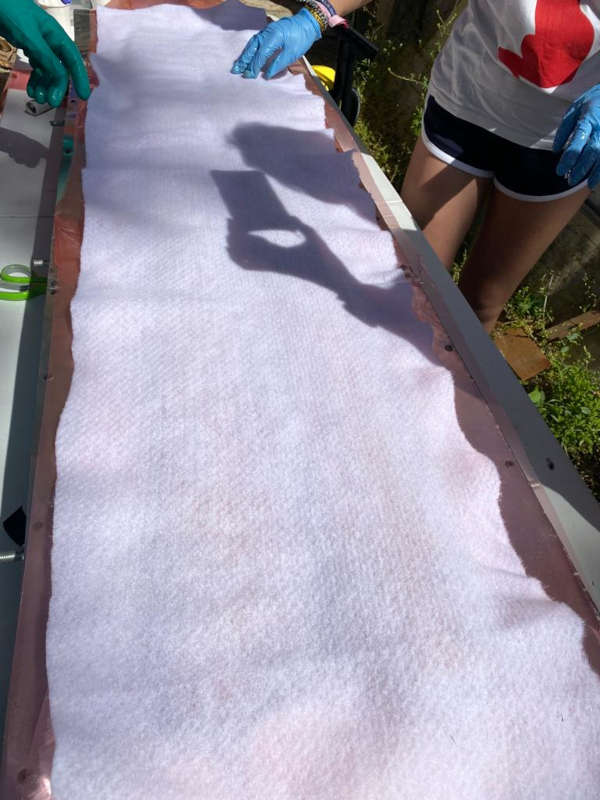
12-A polyethylene sheet. With this we avoid the epoxy resin to stick.
13-A cotton cloth to absorb the excess of resin once it is compressed.
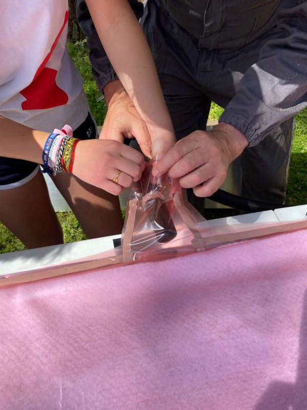
14-After that we put sealant tape on the border of the plastic bag
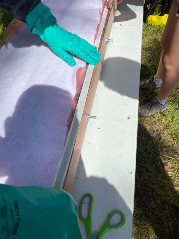
15-To put the top of the plastic bag to make the vacuum bag, adjusting the tube of the vacuum cleaner with sealant and duct tape.
16-To turn on the vacuum cleaner and check the air is going out.
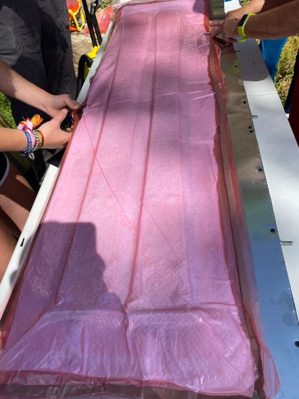
17-To put a rubber mat on the top, so the pressure is well distributed.
18-To put the top of the press and hold it with steel bar clamps.
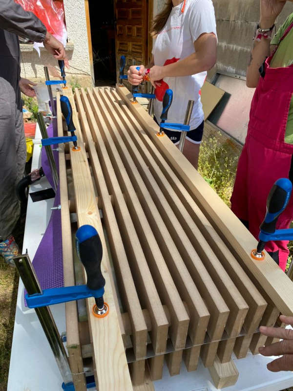
19-To wait 24h to open the press. Before opening I checked the remains of resin on the bucket to check its hardness.
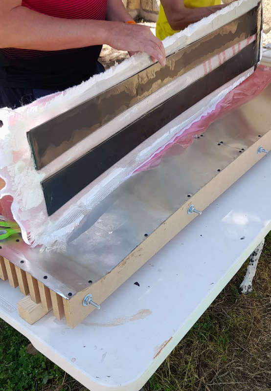
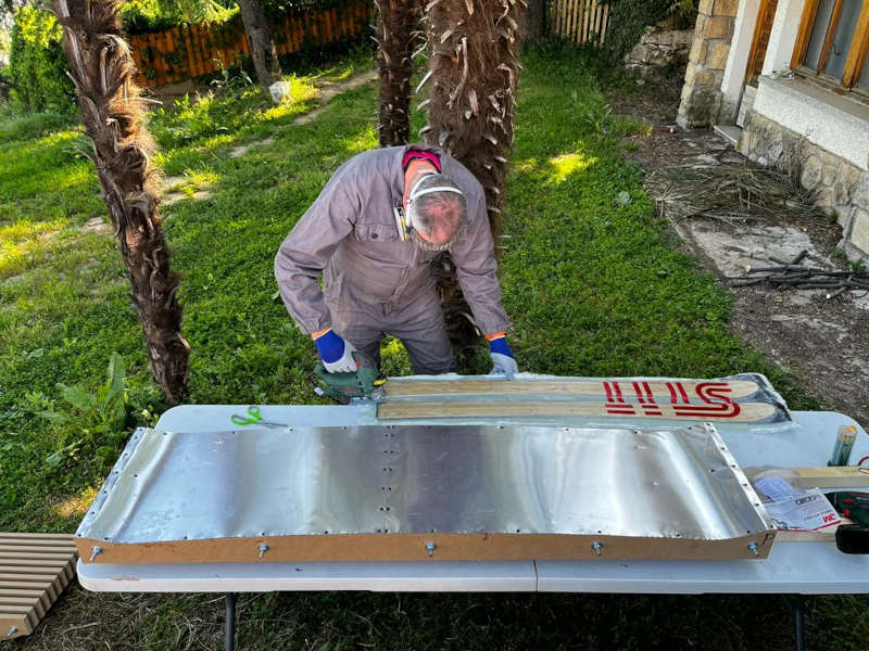
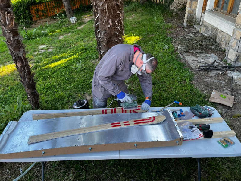
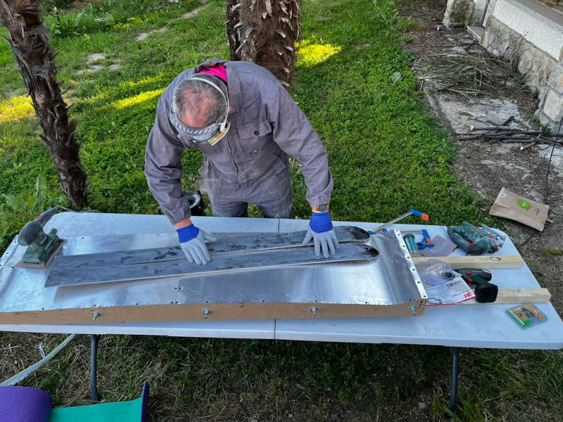
Opening the press
After opening the press I had to cut the shape of the skies with a jigsaw. The steel edges of the ski are very useful to support the blade and cut on the line, but you have to be careful to avoid cutting the edges. Finally I sanded the edges and the bottom of the skies, as they had some epoxy resin on them.


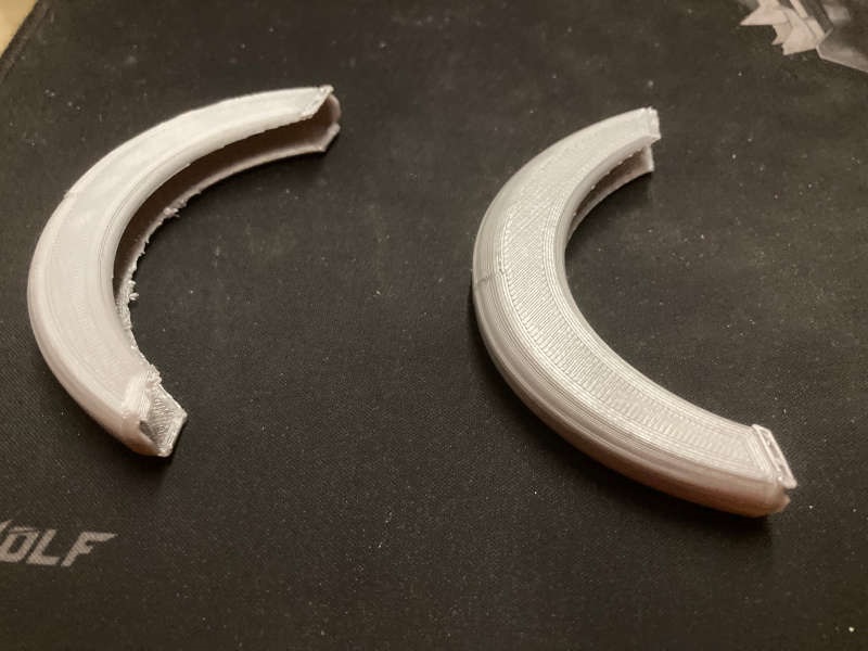
Finally I 3D printed 2 tip protectors:
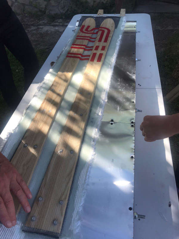
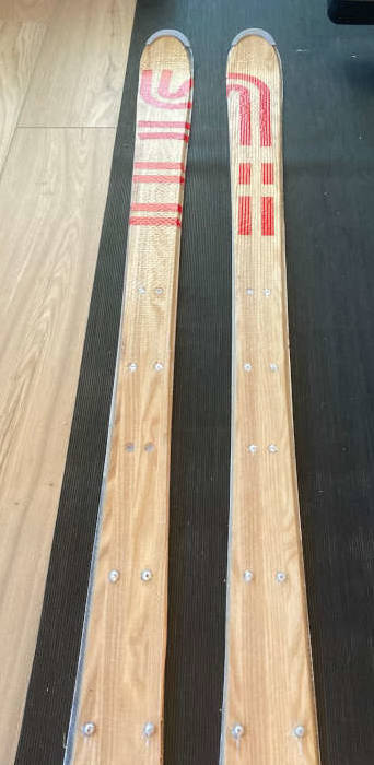
Final result
The result was quite good.The fibers were apparently very tight, and the pattern of the cotton cloth was printed on the surface. .
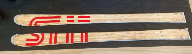
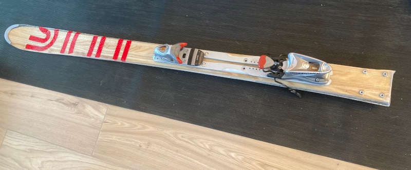
I fixed the bindings to the ski, and they fitted perfectly.
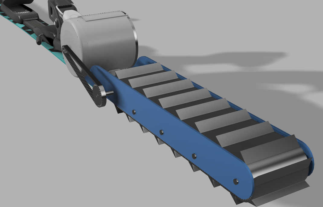
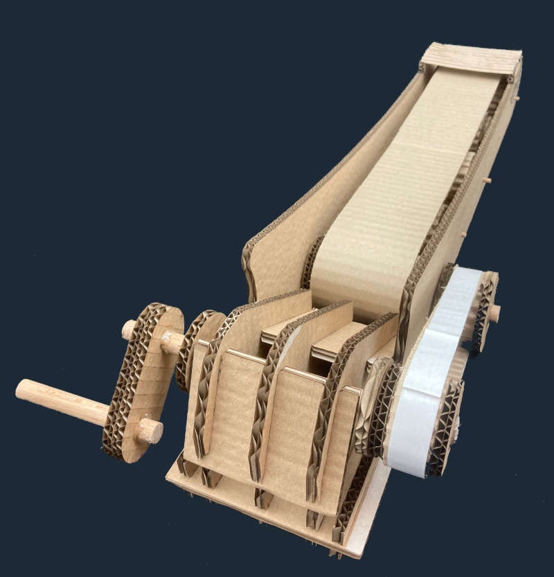
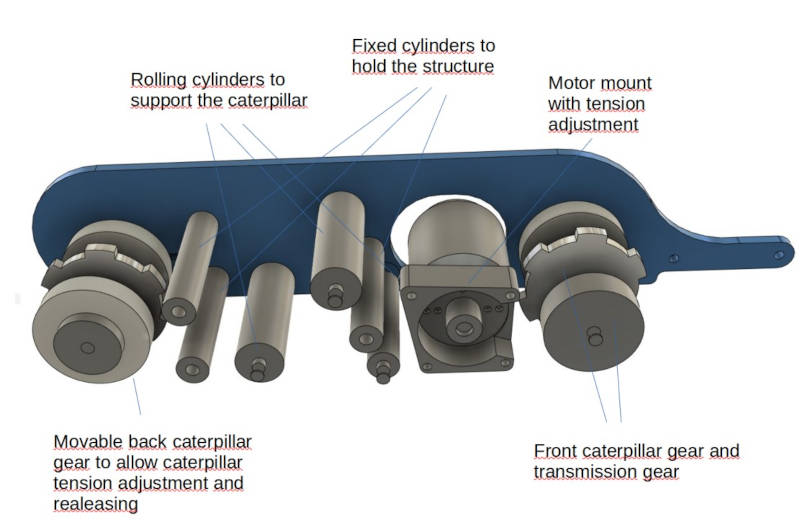
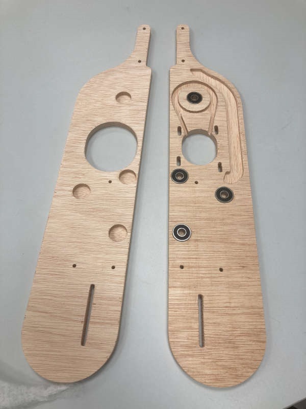
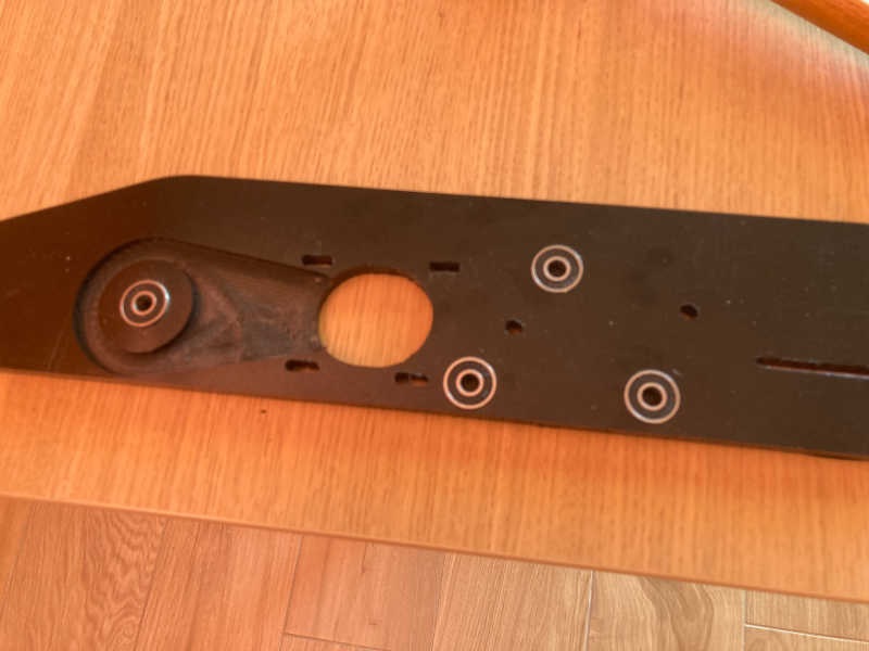
The caterpillar
This is probably the most critical part of my project, and the design of it took me a decent amount of time.
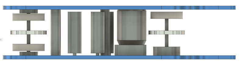
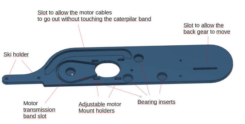
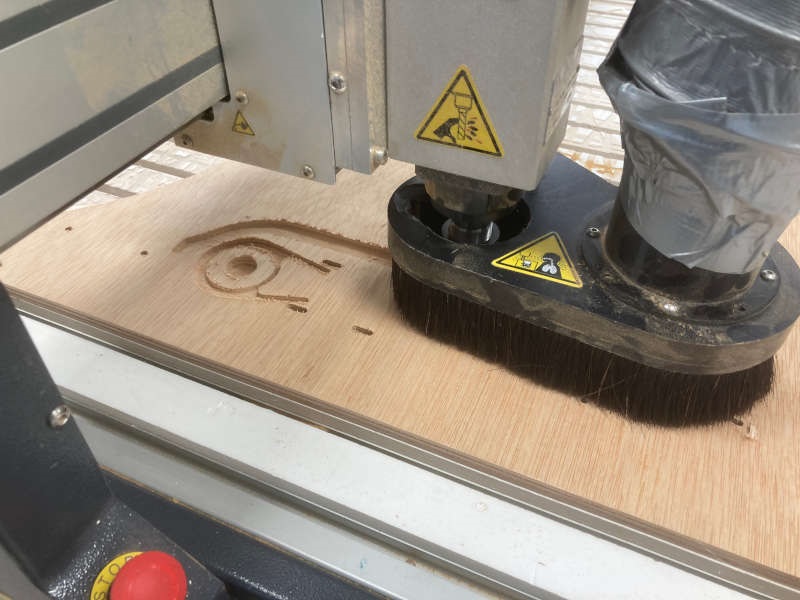
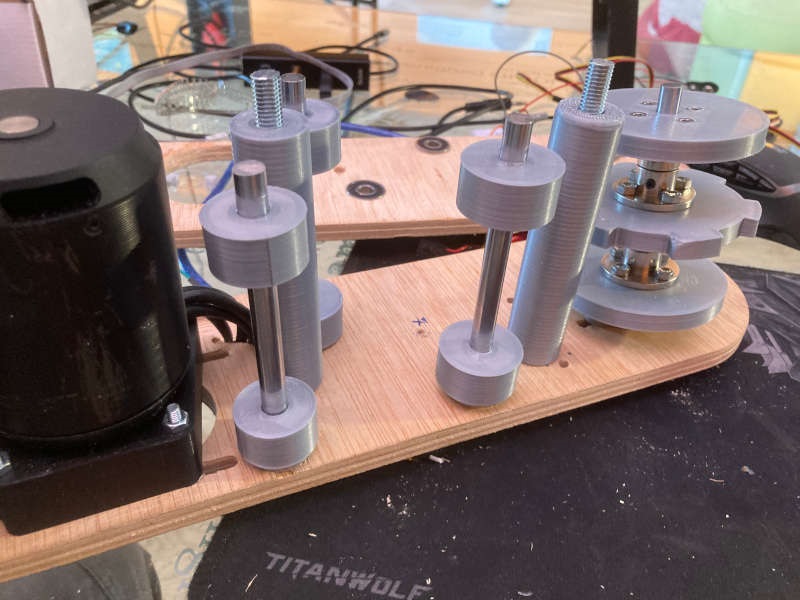
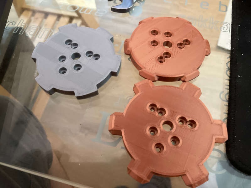
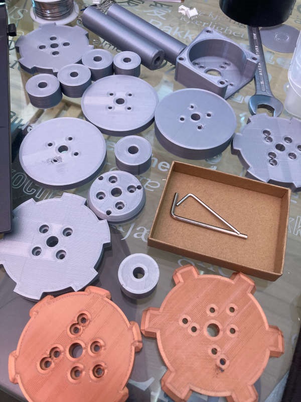
My first thought was to made the two main plates with aluminium. But at the fablab the technicians told me it was better to do it on wood first, because probably it won't be the last version, and it is much more easy to do. They were right, so I milled both plates, cut the shafts and started to make the caterpillar:
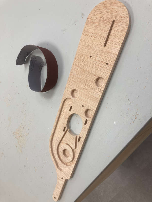
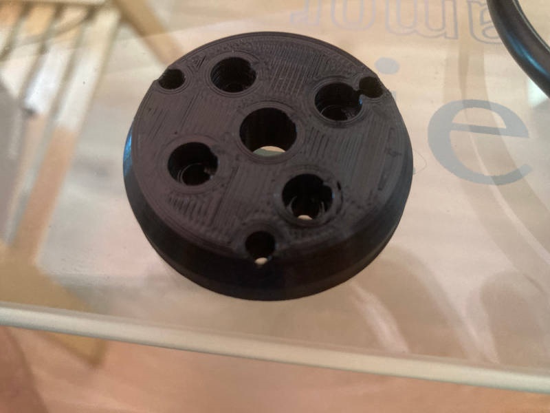
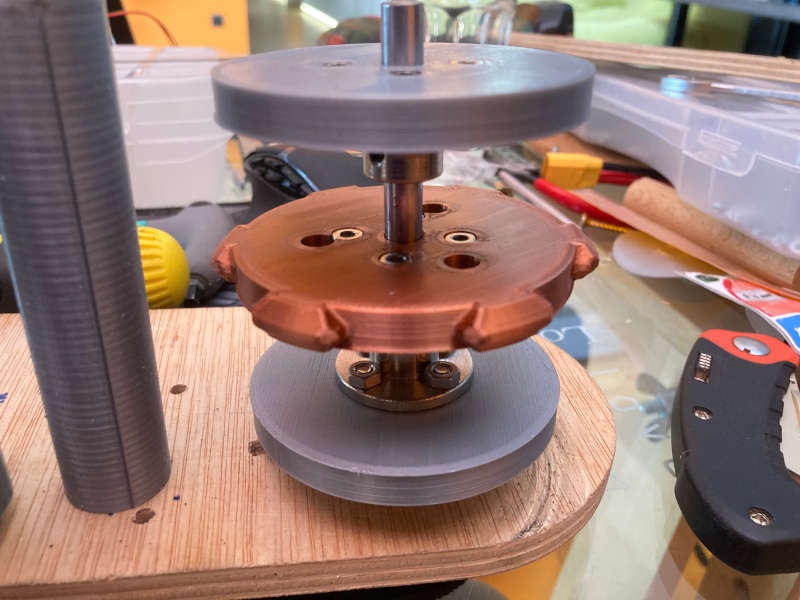
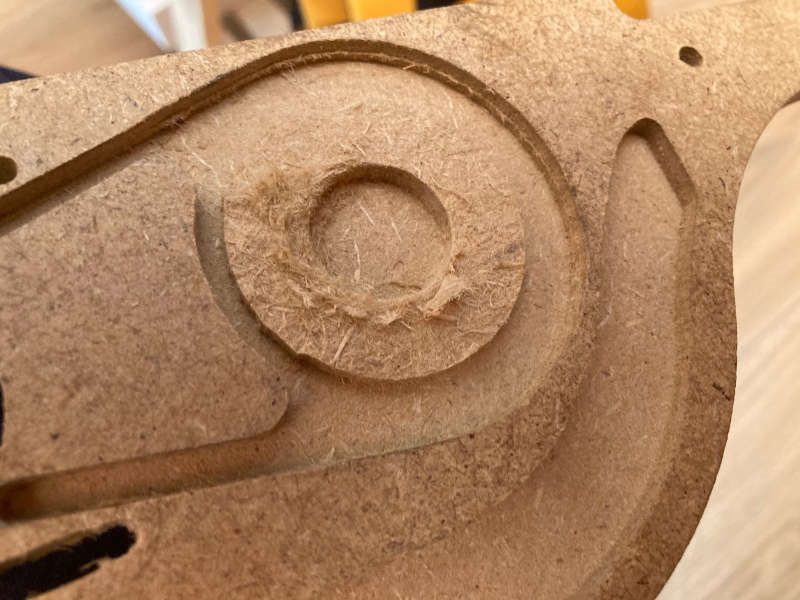
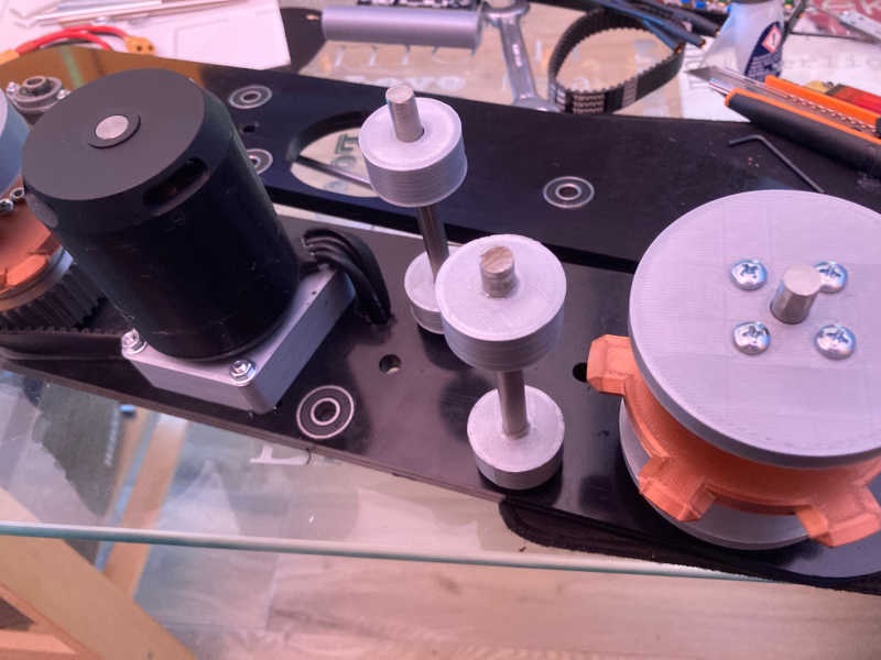
To save space on the front shaft I designed an special piece to hold the transmission gear:
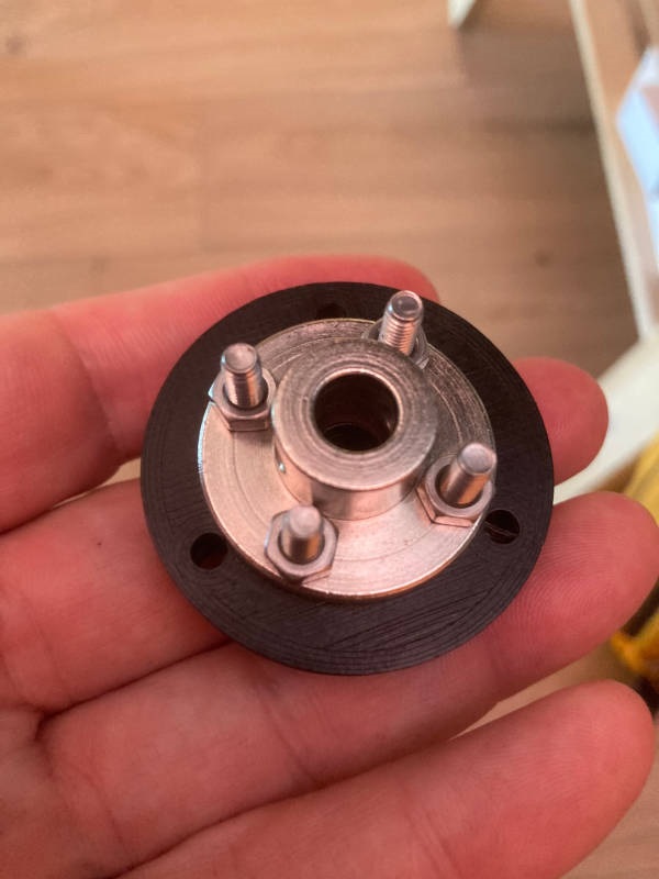
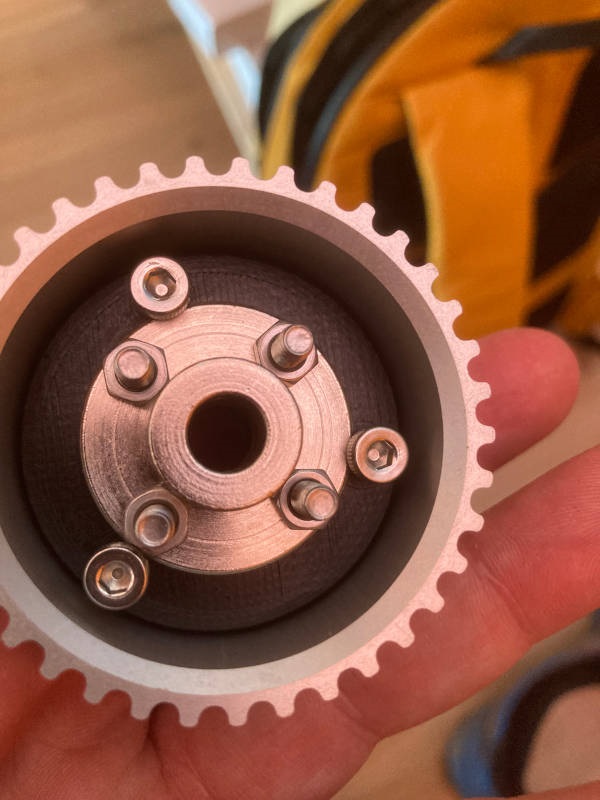
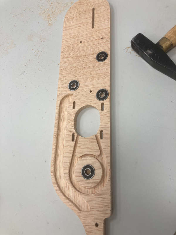
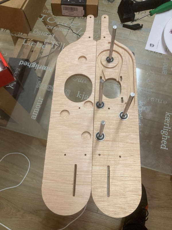
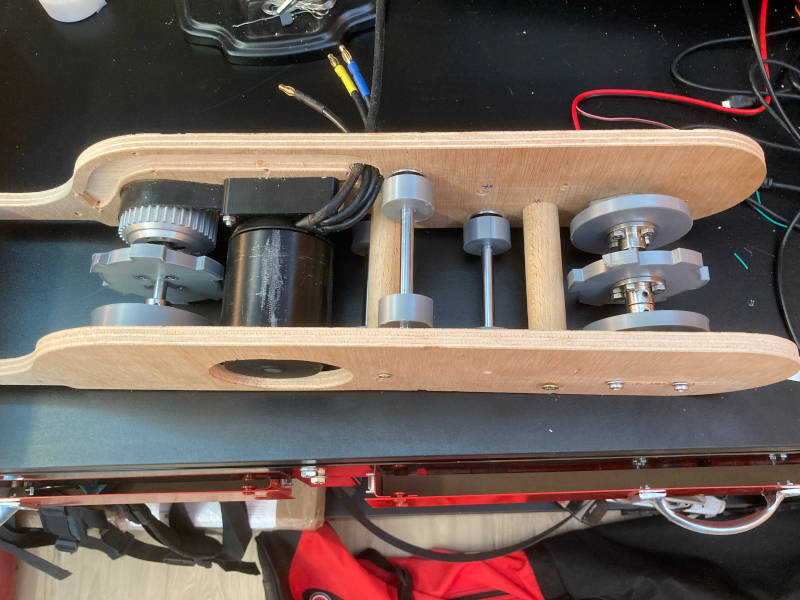
I 3D printed the wheel and the front gear to make the front shaft:
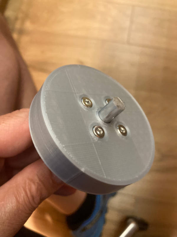
Then I 3D printed the rest of wheels and gears to mount the caterpillar.
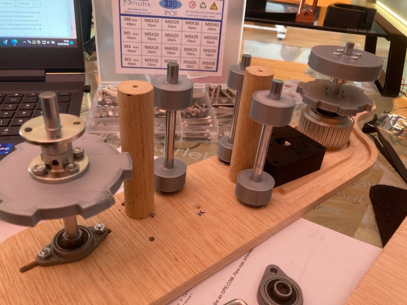
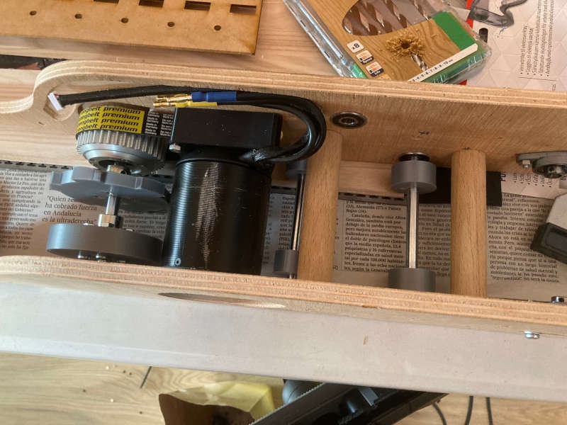
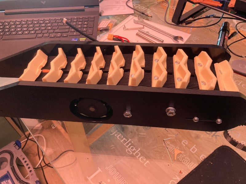
I used the bearing holders (on the picture) and the slots on the plate to allow the shaft to move. So I can adjust the track tension and also release the track when needed.
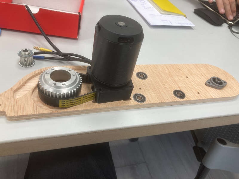
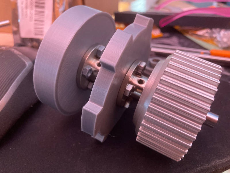
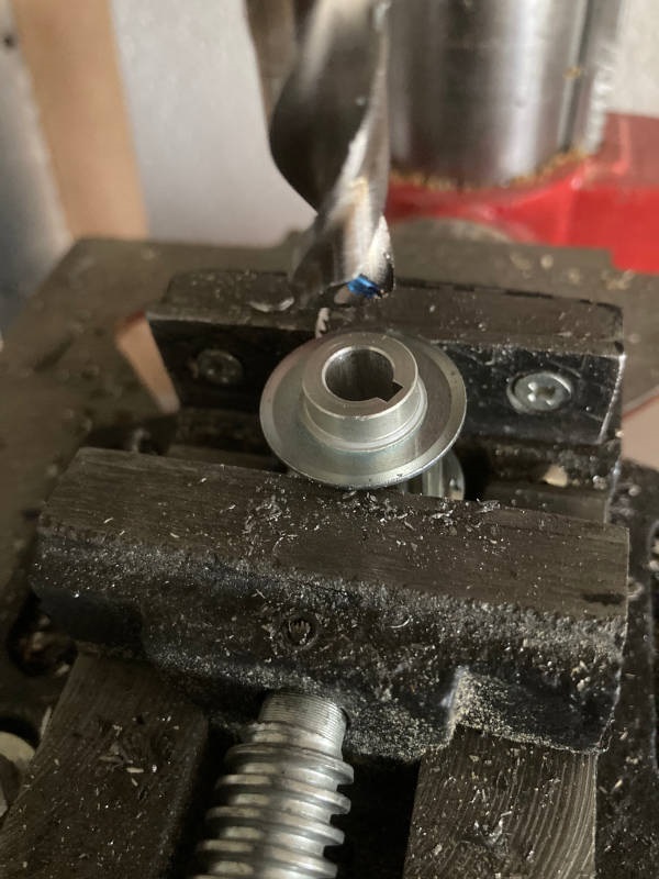
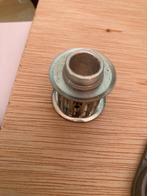
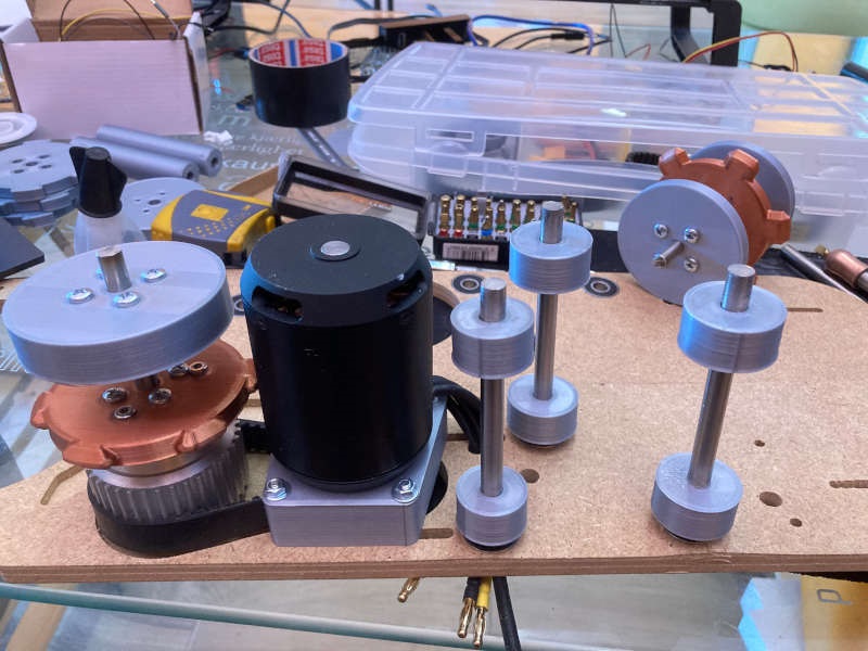
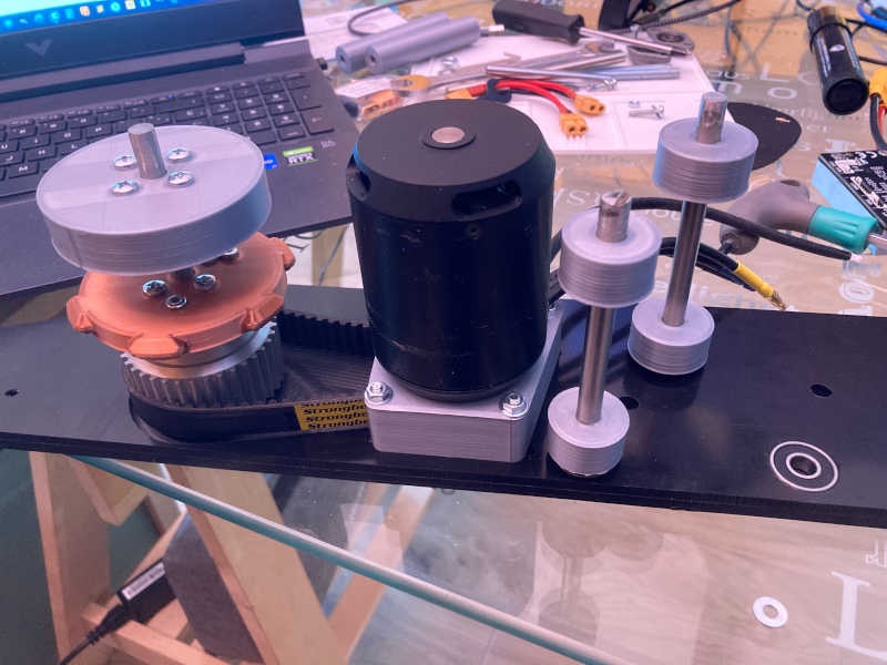
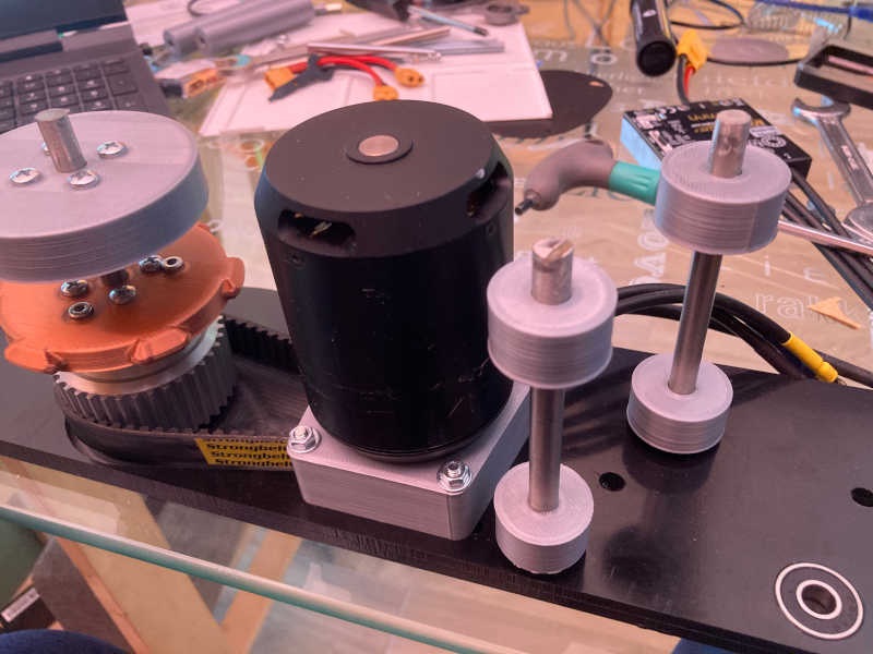
It's time to mount the motor:
The hole of the motor pulley I had was for a 8mm shaft and my motor axle had a diameter of 10mm, so I had to drill the pulley to fit.
It's time to put everything together
After that I tested the motor and main gear:
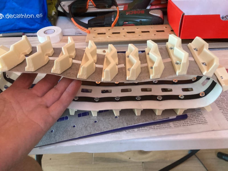
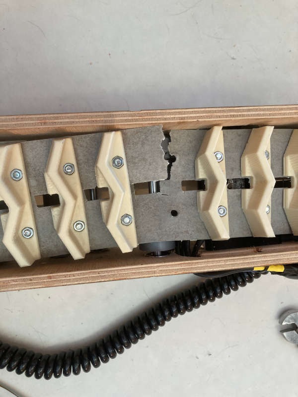
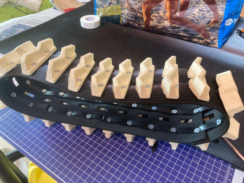
The track
I decided to make the first version of the caterpillar track with vinyl floor, as I thought it was a flexible and hard material.
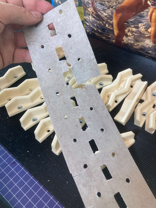
I thought about cutting it with laser, but I found it's not recommended to cut vinyl with laser, because the gases it emits could contain hydrochloric acid, very dangerous for people and even machines.
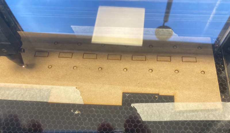
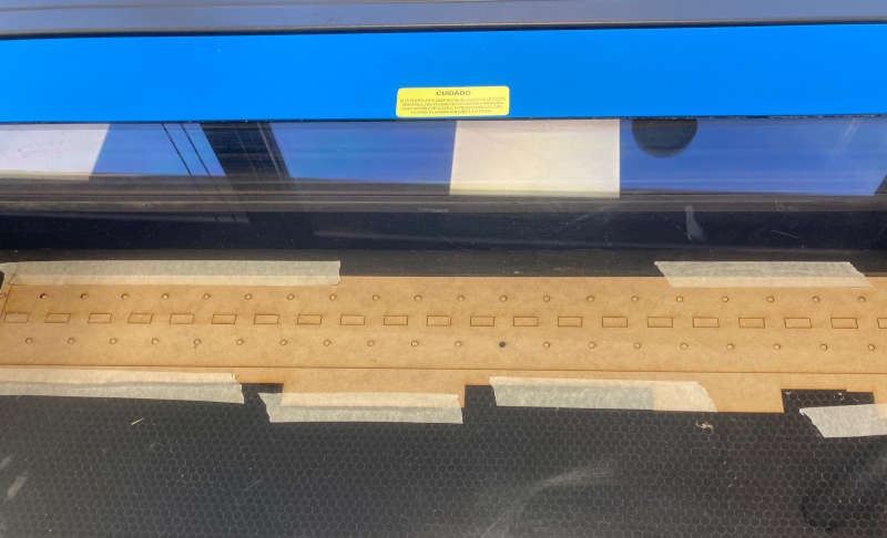
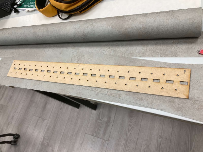
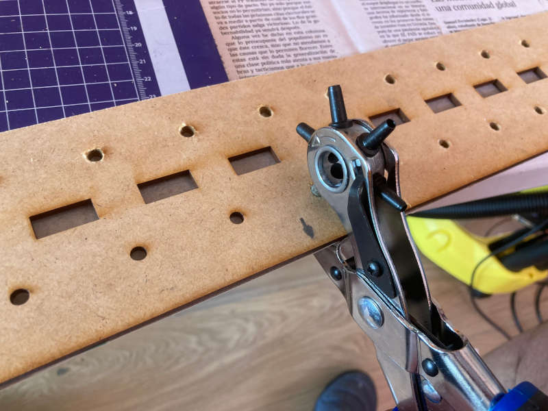
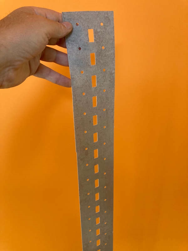
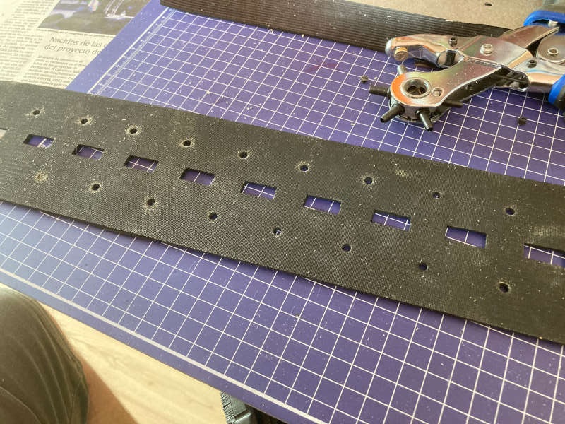
So I made a template cutting MDF with laser, using the template to cut the vinyl floor:
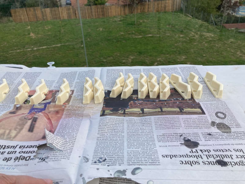
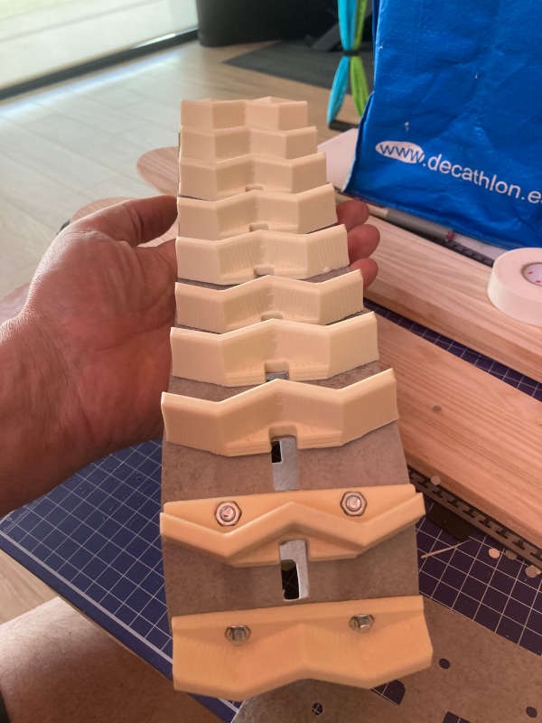
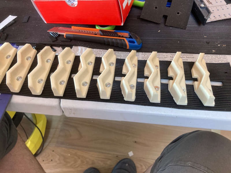
Then I used the pieces I made on the molding and casting week to make the "teeth" of the track:
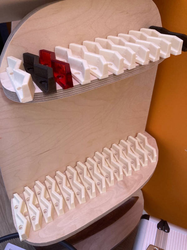
I reinforce the track with some PTEG strips that also help to close the loop and stay on track:
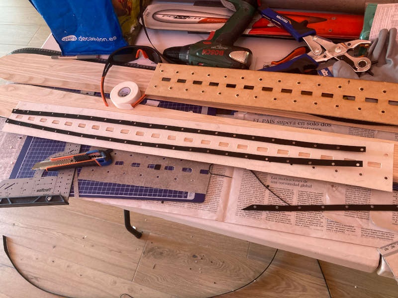
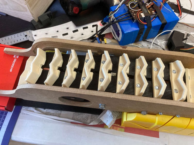
So it's time to screw the pieces and complete the track:
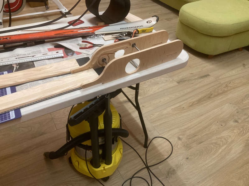
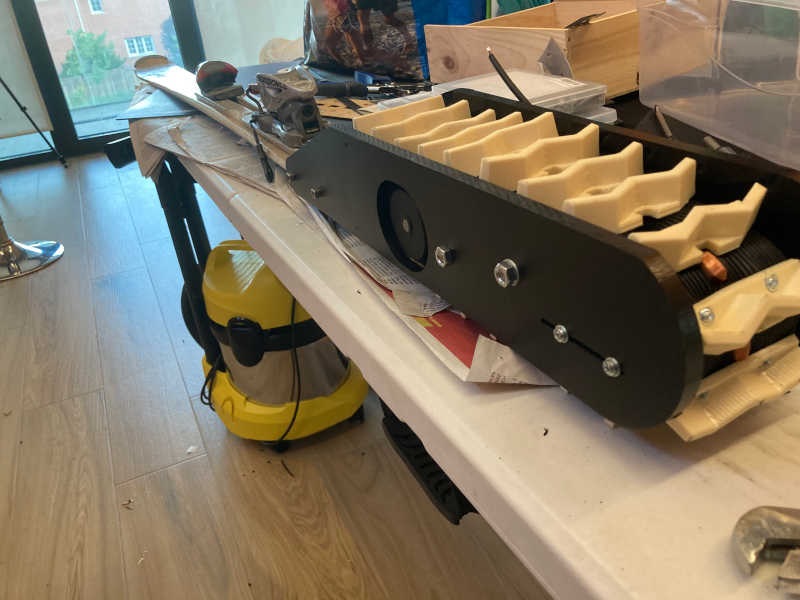
Time to mount the caterpillar
And to make a first test of it (Caterpillar v1.0)
Wow, it works! But anyway, during the different tests I encountered some things to improve:
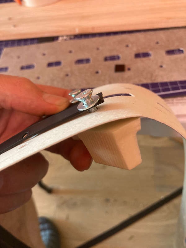
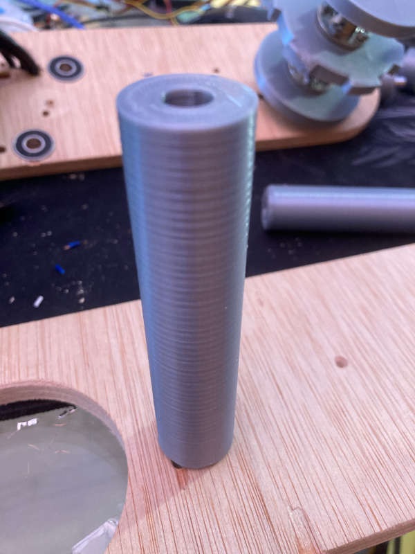
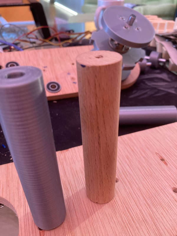
1-The wooden bars that hold the structure are screwed and they wobble a little bit. I think it's better to have some "tubes" and to pass a screw all trough the width of the caterpillar. I 3D printed the tubes with PLA, and the were much better than the wooden bars:
2-The vinyl strip quickly begins to break during the different tests. I replaced it with a strong rubber strip.
3-The gears
Sometimes the tracks goes out of the gears, so I design some gears with more conic profile, so the gear teeth fit into the track slots:

I made all the improvements on the caterpillar to have the V1.1 version of it. The test shows a much more robust caterpillar:
The heat wave
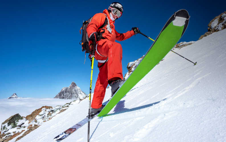
I wanted to go to test Skit on the snow once I had both skis made. But there was a heatwave in Spain and there was almost no snow at all. I was in a hurry.
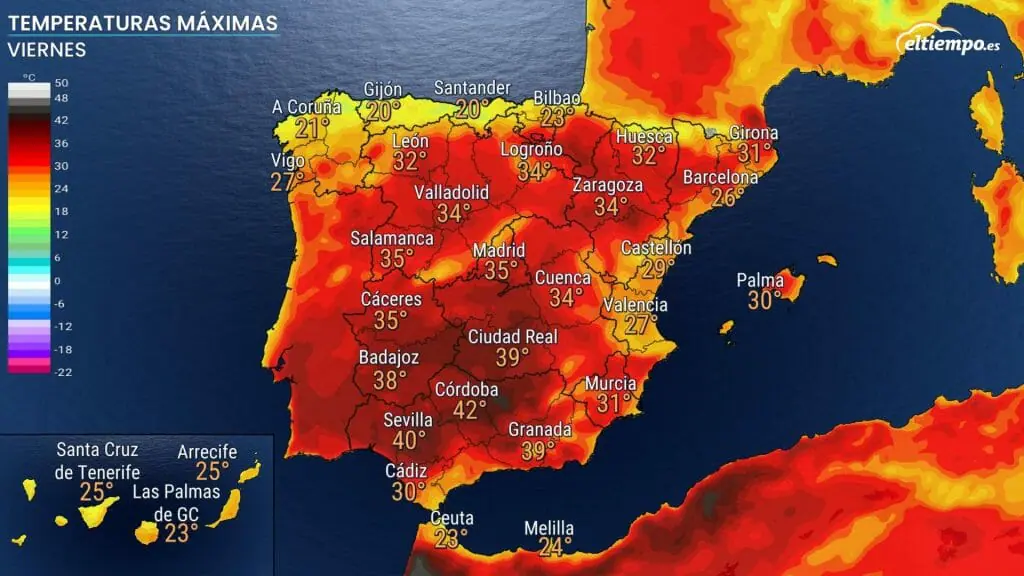
On May 20th I went to the nearer ski station (Valdesquí) to see if there was some snow.
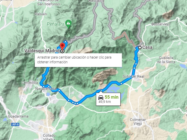
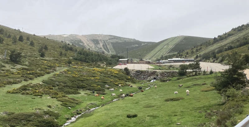
The place was green and beautiful, but there was no snow, just a spot on the top of the mountain, very hard to reach with all the equipment.
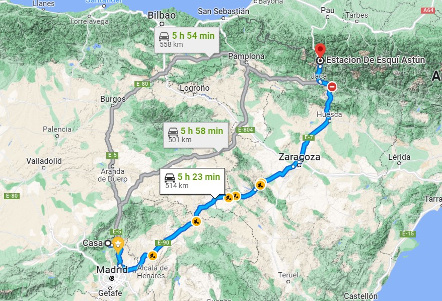
So I took a look at the webcams of ski stations in Spain. It seemed that Astún, on the Pyrenees, has some snow, so I took the skies and went there (550 km from home):
The place was also very green and beautiful, and there was just a spot of snow (5 meters more or less) in the middle of the station, so I decided that at least I could test Skit on the snow.
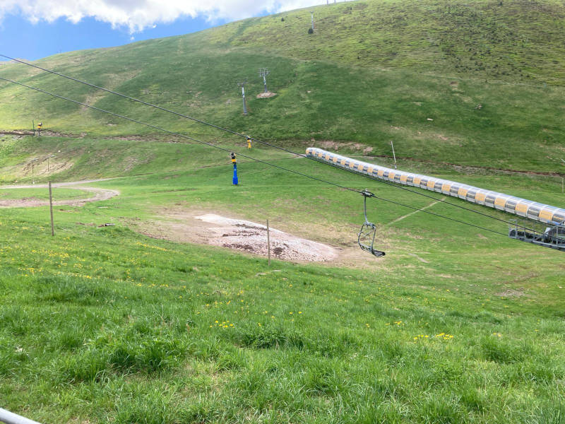
It was a very short test, because there was only that small spot of snow. But anyway it proved the system works. Nevertheless, further tests will be needed to develop a final version of it.
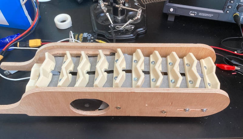
The second caterpillar: MDF wood
I thought MDF wood could be a good material to make a second caterpillar (for the other ski). Because it seems stiffer than plywood and it could be milled with the same settings and gcode files I had for the previous one.
So I milled the plates and made the second caterpillar, printing again all the wheels and gears:

I also molded a new set of "teeth" and made a second rubber track:

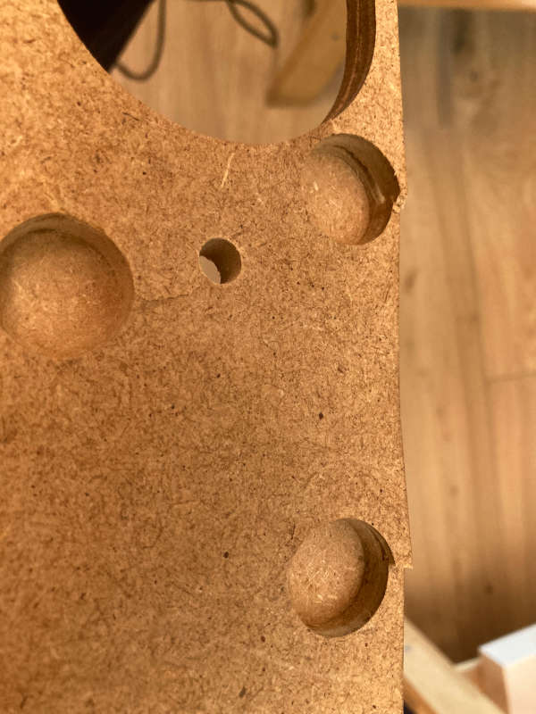
However, I quickly realized that using MDF is not a good idea. The bearing holes didn't fit properly, and it broke when some tension was applied:
At the regional review Nuria told me that it could be a good idea to use HDPE (High Density Polyethylene). It is used by some fablabs to make machines, stiff and easy to mill.
Third caterpillar. Version 2.0 with some improvements and HDPE
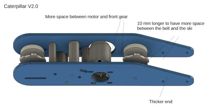
Testing the caterpillars I noticed two main problems with the design:
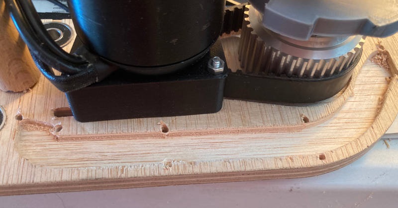
1-The space between the motor and the main gear is very small. So I decided to change the transmission belt, from 275 mm to 330 mm. To do that I have to change the space from the center of motor to the center of the main gear, from 75 mm to 100mm. That implies to change other dimensions of the caterpillar.
2-I noticed that when the system moves quickly, the centrifugal force makes that sometimes a piece of the caterpillar touches the edge of the ski. So I also made bigger that space.
3-The plates are quite narrow at the place they bind to the ski. I made it thicker so they are stronger at that point.
After designing I milled the HDPE plate on the CNC machine to get the new plates:

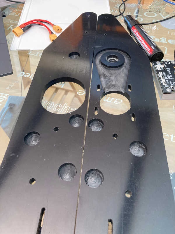
And I mounted all the parts again with the new belt of 325mm:
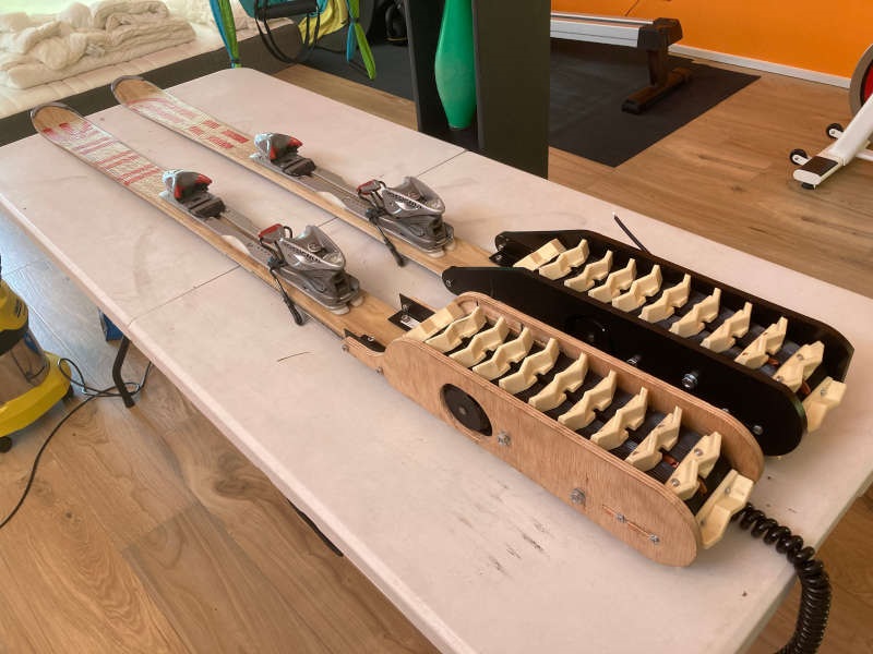
Finally I got the new caterpillar and mounted on the second ski:
It works much better and very smoothly:
I run a test with both skis, and the HDPE caterpillar runs smoother than the wooden one:
After that I decided to make another pair of HDPE plates, so I can have both plates equal.
After that I run a test with both HDPE plates:
System integration
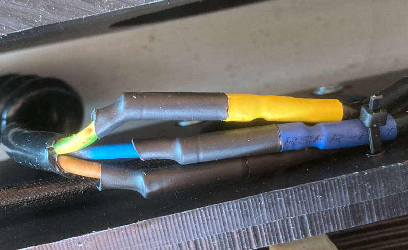
There are many cables, and some with high current passing through them, so it's important to guide and secure them properly.
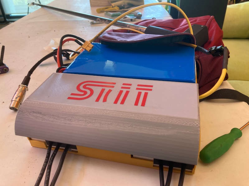
1-The case:
I designed and made an special 3D printed case to hold the battery and the electronic components (2 MCU boards, 2 motor controllers, a switch and cables and connectors).
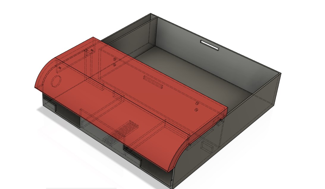
It was 19 hours of 3D printing:
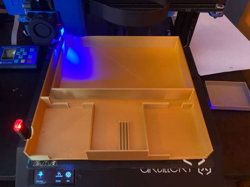
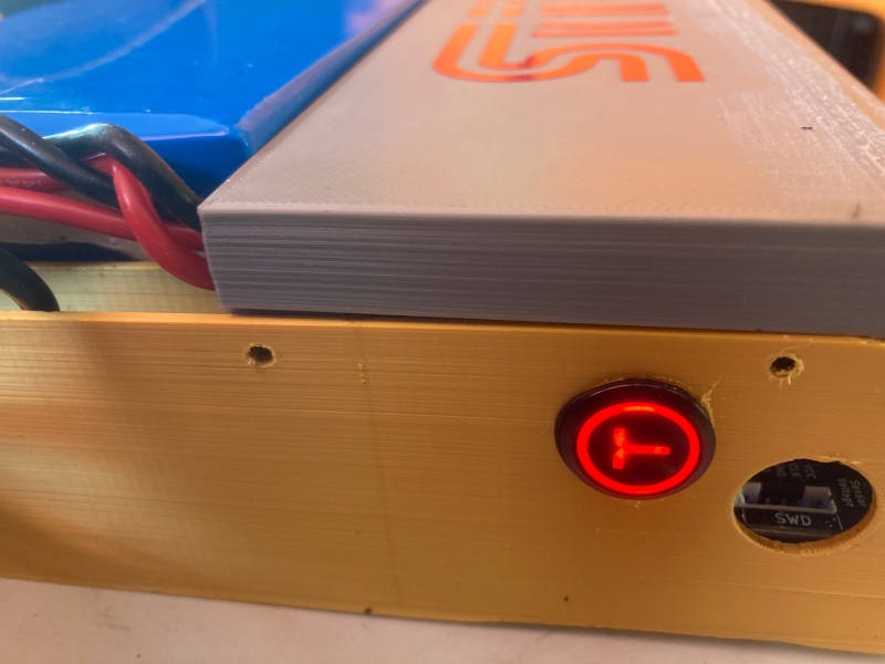
With a space for a switch on one side..
And slots to house the cables:
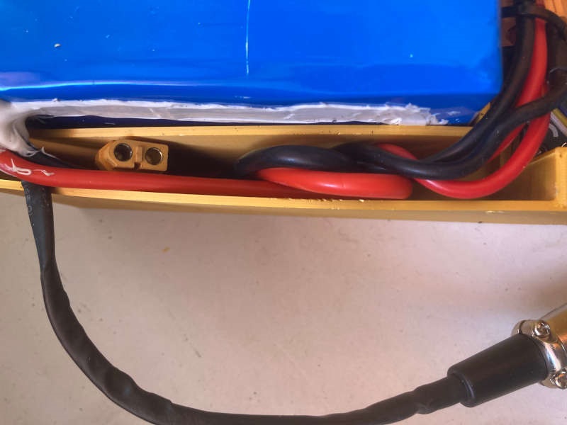
So the electronics elements are fixed and secured:
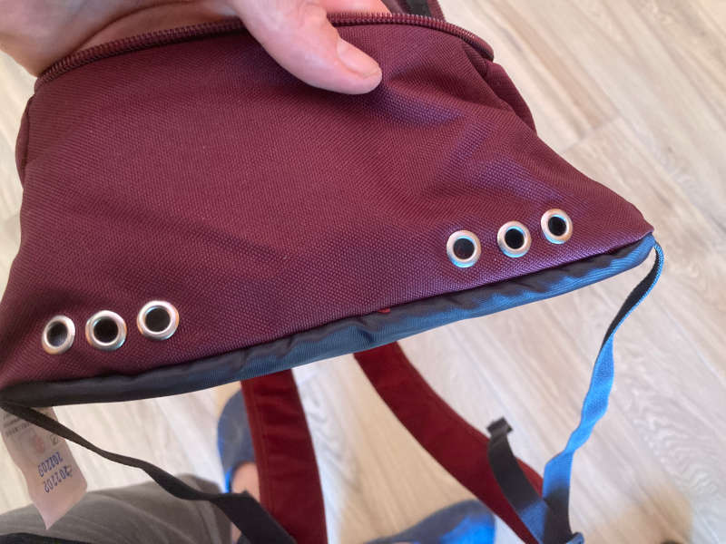
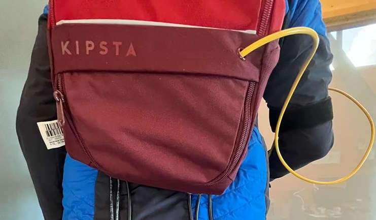
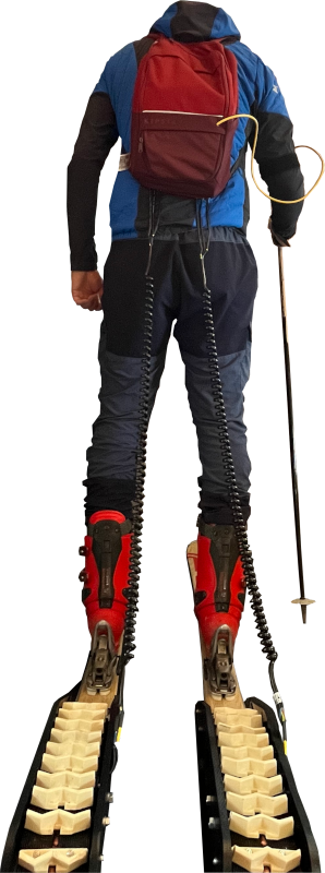
2-The backpack
I put some holes with rivets on a backpack to allow the motor and controller cables to go out:
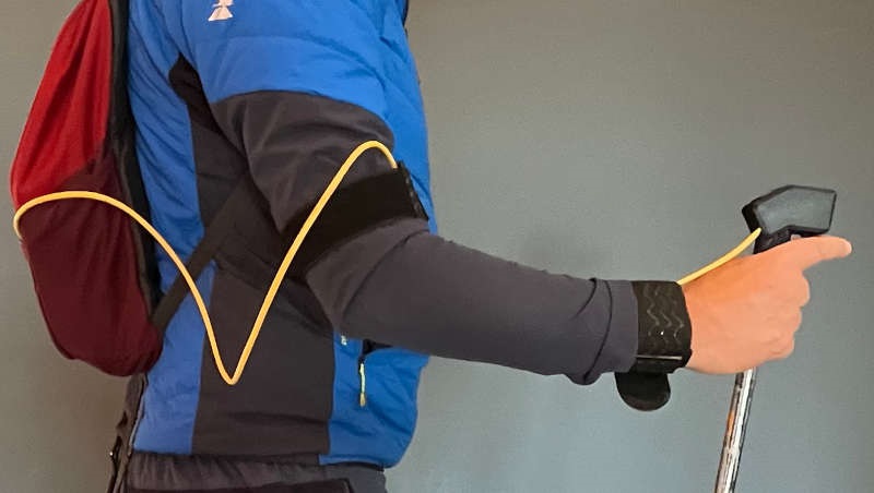
3-Velcro strips to secure the controller wire
I use a pair of Velcro strips to fix the controller wire to the arm. Thank you, Nuria, from FabLab Leon for the tip.

4-Spiral cables to avoid jerks on the power transmission
Thank you, Edu, from Fablab Barcelona, for the tip
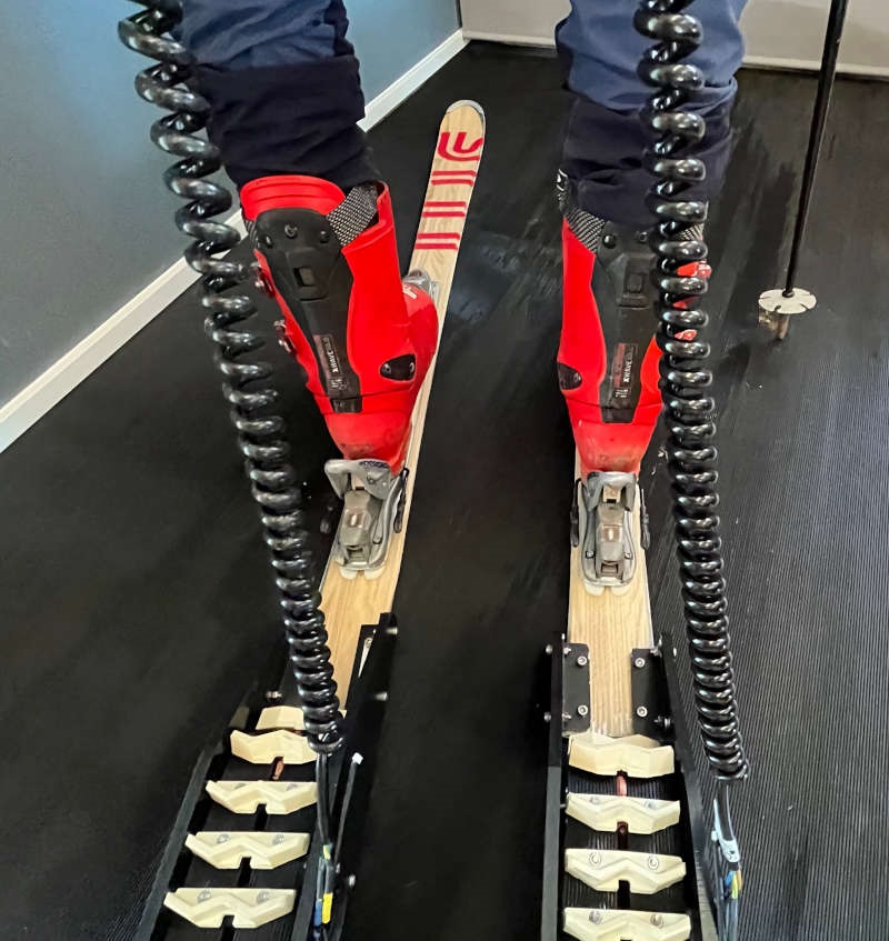
And secured the tips with thermo retractable sleeves to avoid short circuits
And a final integration of everything together:
What tasks remain?
I've explained the tasks completed, but there are still a lot of tasks to do if i want to have a usable and marketable version:
- To make new aluminum plates. HDPE is great for prototyping, sturdy and easy to machine. But a final marketable version will have to be even harder. I think aluminum is a good choice for that.
- More testing: I could only did a short test of the prototype, and results are promising. But a lot of test on the field have to be done to get more feedback and to find the weak parts of it.
- To make new track and studs: Using resin casting to make the studs was a good idea, because it worked and I could apply the knowledge I got during the molding and casting week. But probably a final version must have a "one piece" rubber track, much more sturdy. The tests I made at home proved that the joint of the track is critical, because it suffers a high tension.
- To test new battery placement: To have the battery inside a backpack is great to make the skis lighter, and to have more power. On the other hand, the cables between the backpack and the skis make it more difficult to handle and wear. I would like to make a version with the controllers on the skis, to see the difference.
- To make it wireless: It won't be very difficult to make the controller wireless via Bluetooth, and it would be much more usable.
- To think about the logistics and putting into production: To make a prototype is not so hard, but to produce something at some scale is much more harder. I have to think about the final prototype and its list of materials, the supply chain and the more efficient way of producing it.
Other improvements and ideas
It would be great if the battery is charged with solar energy. A solar jacket with photovoltaic cells all over it would be a great complement for the skis. And it could be also used with electric skateboard, bikes and other electric vehicles.
What has worked? What hasn't?
Some of it is already answered on the remaining task section, but I will resume the things that worked/didn't work:
Things that have worked
- The general concept, the integration of all pieces and the general design.
- HDPE for the final prototype.
- Ski composite making with the exception of some details.
- Electronics worked well from the start and seemed very reliable.
- The 3D printed hand controller works well and has a good feeling
- The caterpillar worked pretty well, but it required some improvements and different versions.
Things that haven't worked
- Vinyl floor for the caterpillar track
- Parallel cable for the controller. I had some interference when the motors went full-throttle. So I change the cable and used a CAT6 Ethernet cable that worked well.
- Motor and gears were too close on the first version of the caterpillar and they almost touched. So I made the second version of the caterpillar with more space.
- Attachment to the skis seemed a little bit weak and I improved them on the second version.
- Space for the track: The centrifugal force made the track studs to touch the tail of the skis, so I had to make it wider.
- The joint of the track is a weak point. I have to make it stronger or to cast a one-piece rubber track.
- Nuts have to be self-locking nuts. The vibration of the motor, gears and wheels makes the nuts loosen up. Self-locking nuts are a must.
- The base of the skis have some marks on them because the high pressure of the press. Next time I will put some rubber mat under the skis to avoid this.
What questions need to be resolved?
There are still very important questions to solve, most of them regarding the performance of the project:
- What's the real range of Skit?
- What's the maximum speed it reaches?
- What's the time autonomy of the battery?
- What's the maximum slope grade?
- And the maximum skier weight it supports?
What will happen when?
During summer I will improve the project, making a more sturdy rubber track and milling in aluminum the most critical pieces.
I also will make a version with the battery on the skis and with a wireless controller, so it's much more easy to handle.
Next winter I'll will do an intensive testing of the prototypes, getting feedback to make a beta version of Skit.
In parallel I will make a final list of materials, logistics and a sketch of a production plant.
What have you learnt?
Wow, I've learnt a lot. The main thing I learned is that I could do it. With the skills I got in Fabacademy almost anything is possible. So I got a lot of self-confidence on being able to do (almost) anything. Taking the motto from Nike, "just do it".
I've also learnt a lot about the different battery models and capacity, BLDC motors and controllers, the way they have to be connected and the security issues you have to take into account (cables current capacity, max current charge and discharge, fuses and switches, etc..).
Of course I learned the skills of Fabacademy and applied them to my project (2D/3D design, cutting, 3D printing, CNC machining, electronics design, production and programming, molding and casting, composite making...).
I also learned a lot from the people that helped me, specially on the mechanical side: Tolerances, type of bearings, shafts, points with stronger tensions, etc..
Files
2D design
3D design
Controller small window .step .f3d
Gear internal holder .step .f3d