Week 13: Networking and communications

Group assignment:
Send a message between two projects
This is the link to the group assignment. However I copied here most of the project:
For the group assignment Pedro and I decided to communicate, vía Tx-Rx, assyncronous network, one of Pedro's boards (an ATtiny1614) as the bridge, with one of Jon´s boards (Another ATtiny1614) as the node, which is also connected to an HC-06 bluetooth module, and that to the computer. So the communication will go as follows:
| Network: Tx-Rx. Brige -> Node. |
| Brigde: Communicates with node, and sends a "Hello" message via Serial. |
| Node: When node called, runs the code programmed -> Recieve "Hello" message from Serial and send it to a computer vía Bluetooth. |
| Computer: Linked to Bluetooth, receives the "Hello" message from the node. |
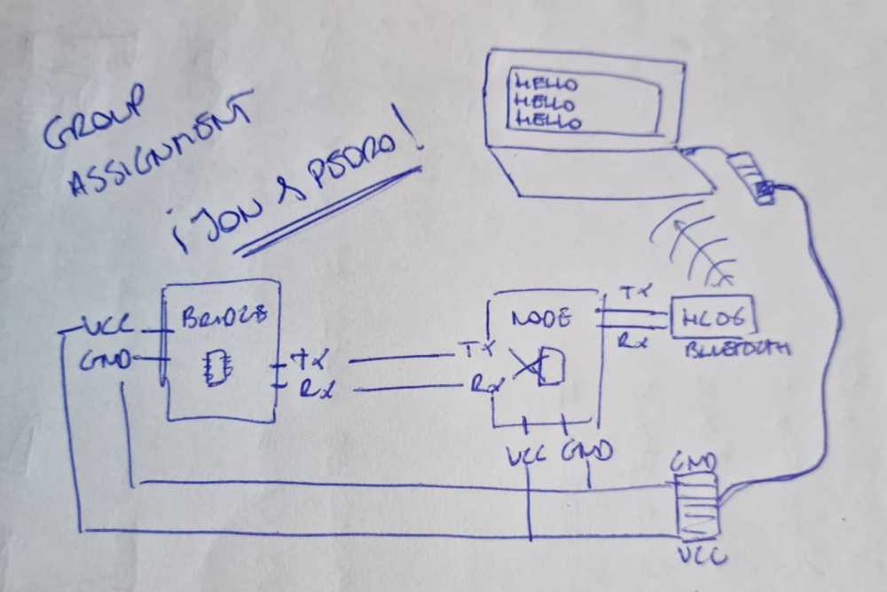
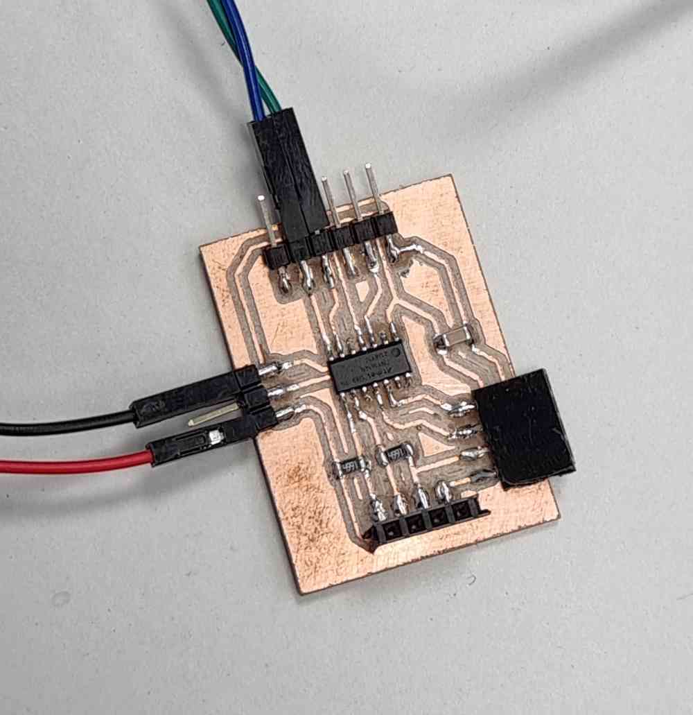
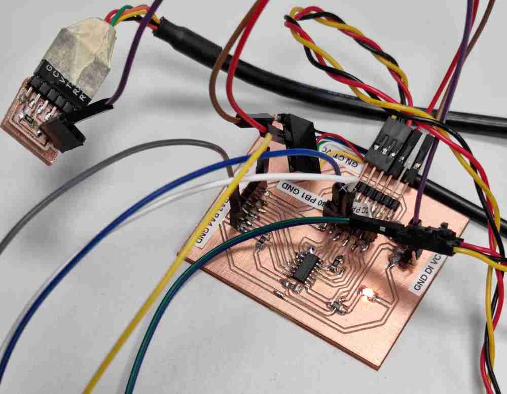
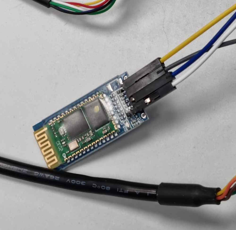
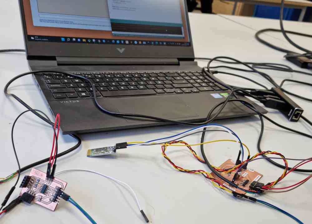
To prepare the "hardware" connections, we used a Tx-Rx connection between the bridge and the node, and the bridge got VCC and GND from it´s own UPDI serial + VCC. The Node, apart of being connected to the brige and having it´s own GND and VCC power connection, from another UPDI serial + VCC, it had also a Tx-Rx connection to an HC-06 Bluetooth module. And the Bluetooth module, was paired to a laptop, where we could see what was being sent.
To prepare the "software" coding, we coded first the bridge program using the same procedure as the individual assignment. But this time with only one address and with the aim of sending trough the serial a "Hello" message.
int adress = 1;void setup() {Serial.begin(9600); //initialize serial communications}void loop() {Serial.print(adress);Serial.print(",");Serial.println("Hello"); // print value to Serialdelay(2000);}
For the Node, we programmed it to send the "Hello" message form the serial, and if there´s no serial communication, to print "waiting". And that´s what it´s going to be sent via Bluetooth and visualized, in our case, in the laptop.
#include <SoftwareSerial.h>String readString;SoftwareSerial Pedrojon(6,7);void setup(){Pedrojon.begin(9600);Serial.begin(9600);}void loop(){Pedrojon.print("Esperando");while (Serial.available()){delay(3);char c = Serial.read();readString += c;}Pedrojon.print("Dato recibido: ");Pedrojon.println(readString);}
Here below you can see a video of how it went:
Things I learnt from the group assignment:
1-Depending on the protocols and processors you are using, the speed of the transmission is a critical parameter. We found that some processors as the ATtiny45 have problems managing high speeds, but work properly at 9600 bauds..
2-Delay times are also sensistive. You have to wait for the signal to appear and also for the signal to go down, so the delay times are important.
3-Regarding bluetooth, once the comm is established you can manage it as a common serial port. But on the PC sometimes the ports are not properly released and they appear as "busy" (specially if you are testing and switching it on and off). So, it's important to check serial ports and Bluetooth devices connected on the configuration.
Individual assignment:
Design, build, and connect wired or wireless node(s) with network or bus addresses.
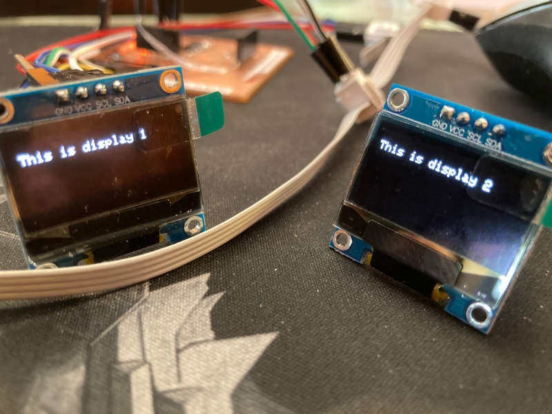
2 OLED display on the same I2C bus
What I wanted to do is to put 2 OLED displays on the same I2C bus, so the wiring is the same for both, I only use 2 pins on the MCU (SCL and SDA), and I send the information to the display I want using the address on the bus.
First thing I have to do is to change the address of one of the OLED displays. To do that I have to desolder and solder a small resistor at the back of the display:
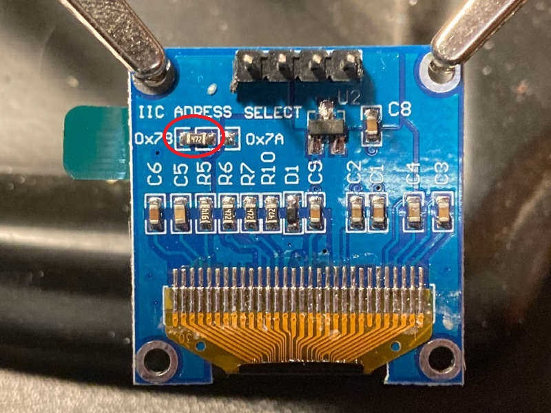
By default the address of the OLED is 0x3C (60 in decimal). I don't know why on the board it says the double, 0x78 (120 in decimal). Changing the resistor to the right the adress will be 0x3D (61 in decimal), 0x7A on the board (122 in decimal).
I desoldered the resistor just heating both sides and pulling with the tweezers. And I soldered on the right:
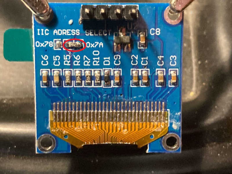
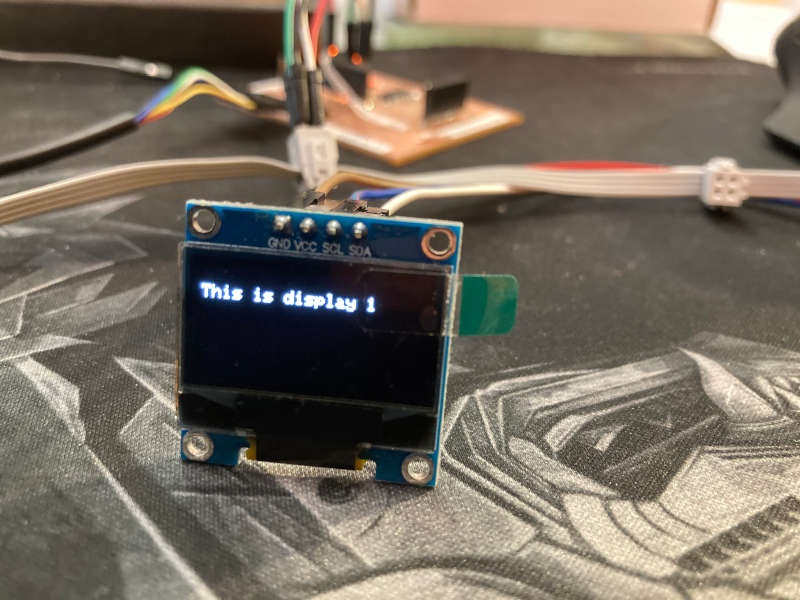
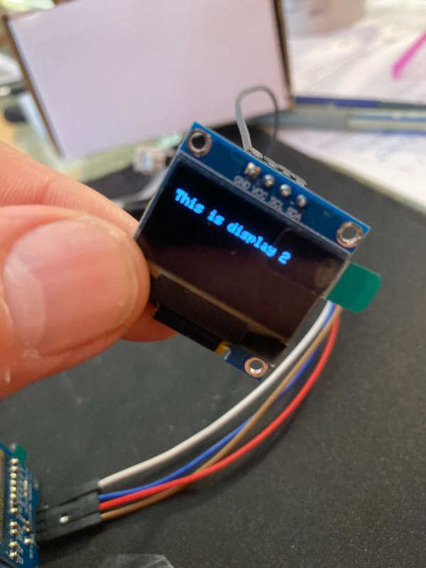
So now I have an OLED display with the 0x3C address and another one with 0x3D adress.
I used the ATtiny1614 generic board I made on week 10, and the two OLED displays.
The connections are quite simple, just building the I2C bus:
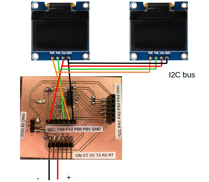
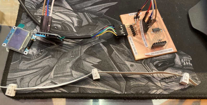
Making the I2C bus with 4 wires flat cable (SDA, SCL, VCC and GND)

So, for the code, you just need to launch 2 different instances of the display and address each of them on the correspondent I2C adress (0x3C and 0x3D):
#include <Adafruit_GFX.h>
#include <Adafruit_SSD1306.h>

#define SCREEN_WIDTH 128 // OLED display width, in pixels
#define SCREEN_HEIGHT 64 // OLED display height, in pixels

// Declaration for an SSD1306 display connected to I2C (SDA, SCL pins)
Adafruit_SSD1306 display1(SCREEN_WIDTH, SCREEN_HEIGHT, &Wire, -1);
Adafruit_SSD1306 display2(SCREEN_WIDTH, SCREEN_HEIGHT, &Wire, -1);

void setup() {

display1.begin(SSD1306_SWITCHCAPVCC, 0x3C); // Address 0x3C for display1
display2.begin(SSD1306_SWITCHCAPVCC, 0x3D); // Address 0x3D for display2

delay(2000);
  display1.clearDisplay();
  display1.setTextSize(1);
  display1.setTextColor(WHITE);
  display1.setCursor(0, 10);
  // Display static text
  display1.println("This is display 1");
  display1.display();

 delay(2000);

  display2.clearDisplay();
  display2.setTextSize(1);
  display2.setTextColor(WHITE);
  display2.setCursor(0, 10);
  // Display static text
  display2.println("This is display 2");
  display2.display();

}

void loop() {

}
The first time I had some problems on both displays, showing some "snow" on the screens. I realized I had to revise the soldering of the small resistor. I added some solder and checked that the solder flowed correctly. And the problem was solved.
Communication of 3 nodes by serial bus TX/RX
After playing with the addresses of the I2C bus, it's time to connect 3 boards to the same serial bus. So I took the ATTiny1614 board and two ATTiny45 boards. The ATTiny1614 board will be the master and the two hello boards will be the slaves. I will use the TX/RX pins of the FTDI connectors of each board.
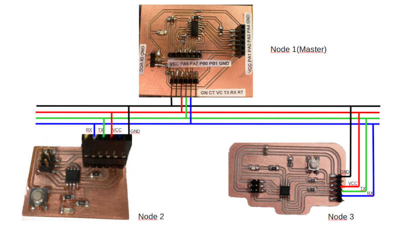
At first I didn´t use a LED on the master, so I send a value to the bus and the slaves will blink the led only if the value represents the number of the node.
This is the code for the master:
//code made by Jon Merino, based on the code of Neil Gershenfeld and Adrian Torres//Fab Academy 2022//Fab Lab UE Madrid//ATtiny1614 master//#include SoftwareSerial.h//SoftwareSerial mySerial(2,3); //RX, TXint v=0;int nodeid=1; //Node Identificationint i=0;void setup() {Serial.begin(9600); //initialize serial communications// pinMode(4, OUTPUT); // led}void loop() {for (i=1;i<=3;i++){ // initialization; condition; incrementSerial.println(i); // print value to Serialdelay(1000);}/*while (Serial.available () == 0 ) {} //while serial is 0v = Serial.parseInt();if(v == nodeid) //If the value of v equals the identification of the node{digitalWrite(4,HIGH);delay(200);digitalWrite(4,LOW);delay(200);}else{digitalWrite(4,LOW);}*/}
Code for node 2:
//code made by Jon Merino, based on the code of Neil Gershenfeld and Adrian Torres//Fab Academy 2022//Fab Lab UE Madrid//ATtiny45 node 1#include <SoftwareSerial.h>SoftwareSerial mySerial(1,2); //RX, TX en MISO sckint v=0;int nodeid=2;//Node Identificationvoid setup() {mySerial.begin(9600); //initialize serial communicationspinMode(4, OUTPUT); // led}void loop() {while (mySerial.available () == 0 ) {} //while serial is 0v = mySerial.parseInt();mySerial.println(v);if(v == nodeid) //If the value of v equals the identification of the node{digitalWrite(4,HIGH);delay(200);digitalWrite(4,LOW);delay(200);}else{digitalWrite(4,LOW);}}
Code for node 3:
//code made by Jon Merino, based on the code of Neil Gershenfeld and Adrian Torres//Fab Academy 2022//Fab Lab UE Madrid//ATtiny45 node 2#include <SoftwareSerial.h>SoftwareSerial mySerial(1,2); //RX, TX en MISO, SCKint v=0;int nodeid=3;//Node Identificationvoid setup() {mySerial.begin(9600); //initialize serial communicationspinMode(4, OUTPUT); // led}void loop() {while (mySerial.available () == 0 ) {} //while serial is 0v = mySerial.parseInt();mySerial.println(v);if(v == nodeid) //If the value of v equals the identification of the node{digitalWrite(4,HIGH);delay(200);digitalWrite(4,LOW);delay(200);}else{digitalWrite(4,LOW);}}
The slaves answer to the bus repeating the node number, so the master can listen to it. I added a LED to the master to blink when the node number is 1. I just uncommented the code section of the LED on the master:
//code made by Jon Merino, based on the code of Neil Gershenfeld and Adrian Torres//Fab Academy 2022//Fab Lab UE Madrid//ATtiny1614 master//#include SoftwareSerial.h//SoftwareSerial mySerial(2,3); //RX, TXint v=0;int nodeid=1; //Node Identificationint i=0;void setup() {Serial.begin(9600); //initialize serial communications// pinMode(4, OUTPUT); // led}void loop() {for (i=1;i<=3;i++){ // initialization; condition; incrementSerial.println(i); // print value to Serialdelay(1000);}while (Serial.available () == 0 ) {} //while serial is 0v = Serial.parseInt();if(v == nodeid) //If the value of v equals the identification of the node{digitalWrite(4,HIGH);delay(200);digitalWrite(4,LOW);delay(200);}else{digitalWrite(4,LOW);}}
And finally we can see the three nodes answering to the node number:
Testing Bluetooth
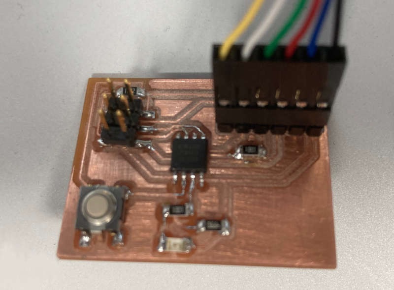
I also wanted to test the communications via Bluetooth, so I connected an HC-06 module to the ATtiny45 board. It was a DSD Tech HC-06 module:
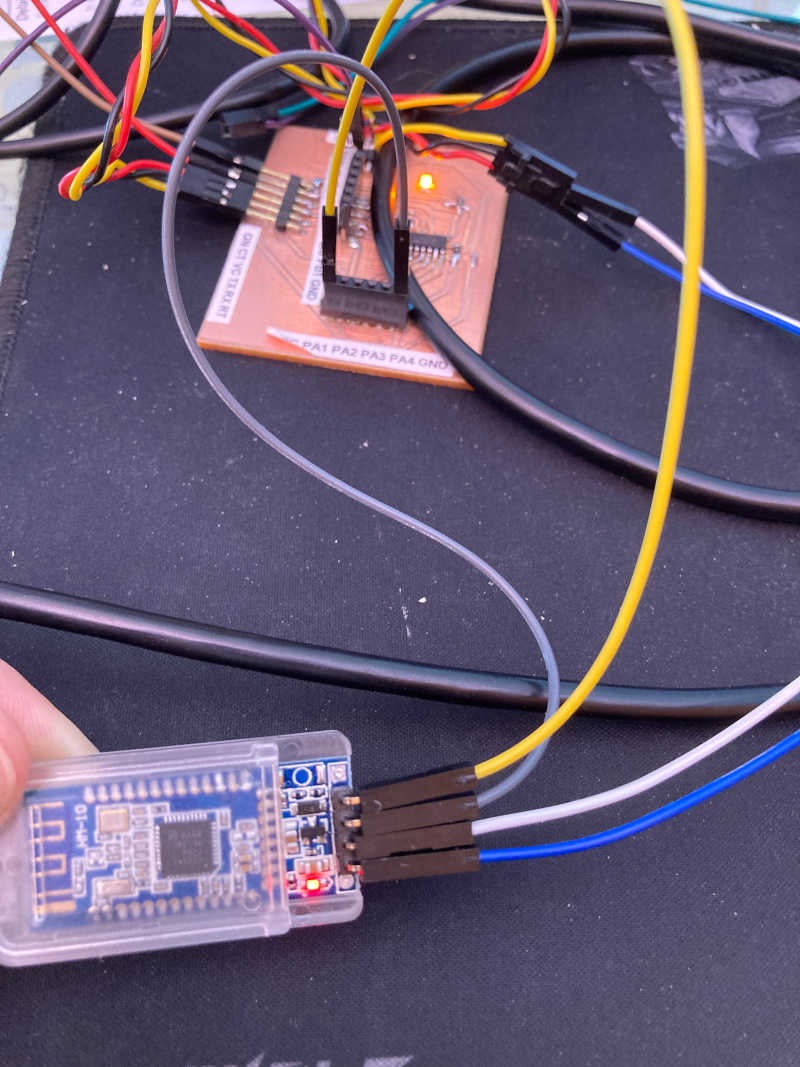
I could pair the module with the PC and an Android Phone, but I couldn't use any Bluetooth service of it. After trying with any device I got at home, I went to the Fablab and used another HC-06 Bluetooth module. This time I could pair and use it, so I connected it to the ATTiny 1614 board:
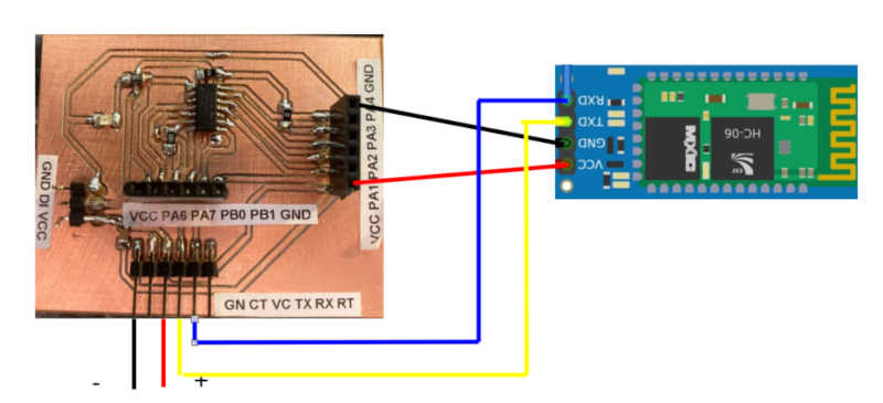
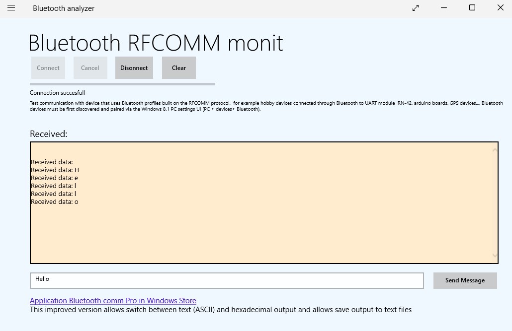
I uploaded a very basic program that answers with the same characters you send to the module:
void setup(){Serial.begin(9600);}void loop(){if (Serial.available()){char dato=Serial.read();Serial.print("Dato recibido: ");Serial.println(dato);}}
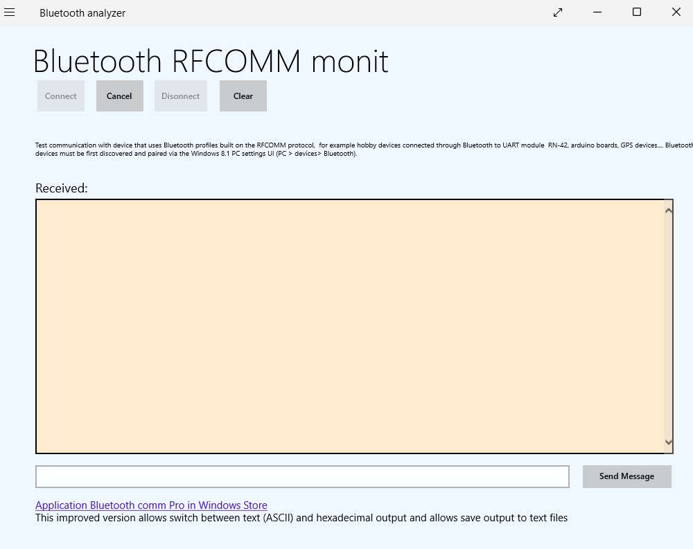
I installed a program to use the Bluetooth interface on the PC, Bluetooth analyzer.
I also had to add the bluetooth device to the PC and pair it:
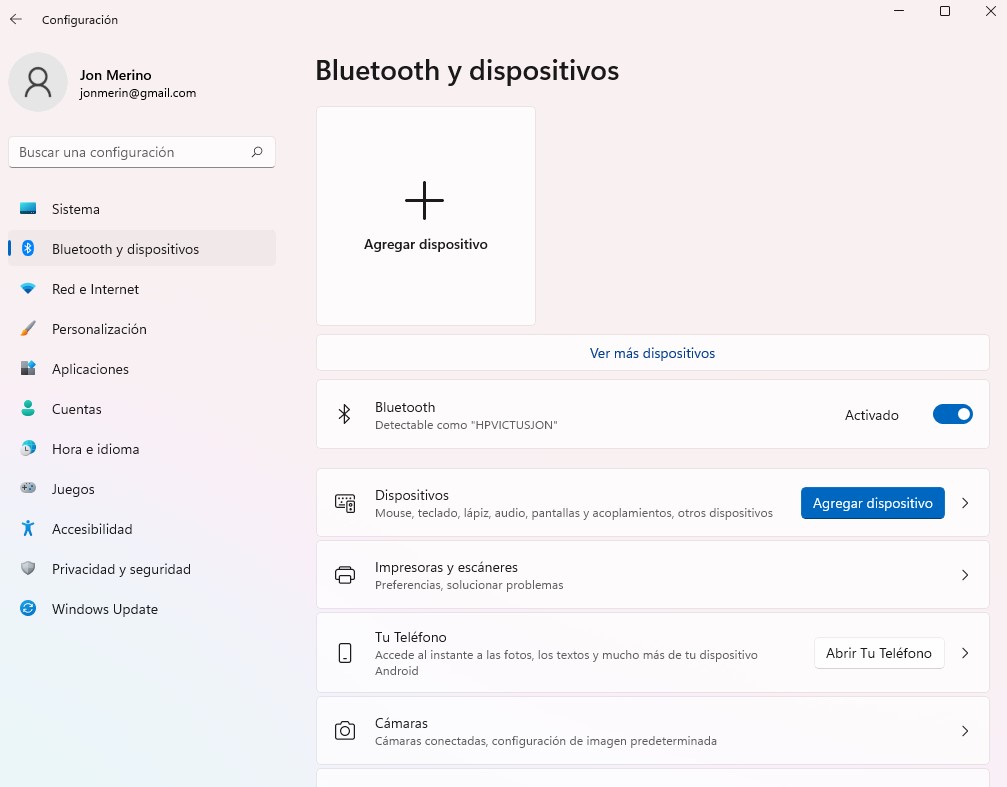
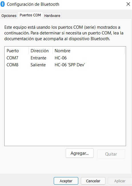
It's also important to check that the COM ports are linked to the bluetooth device.
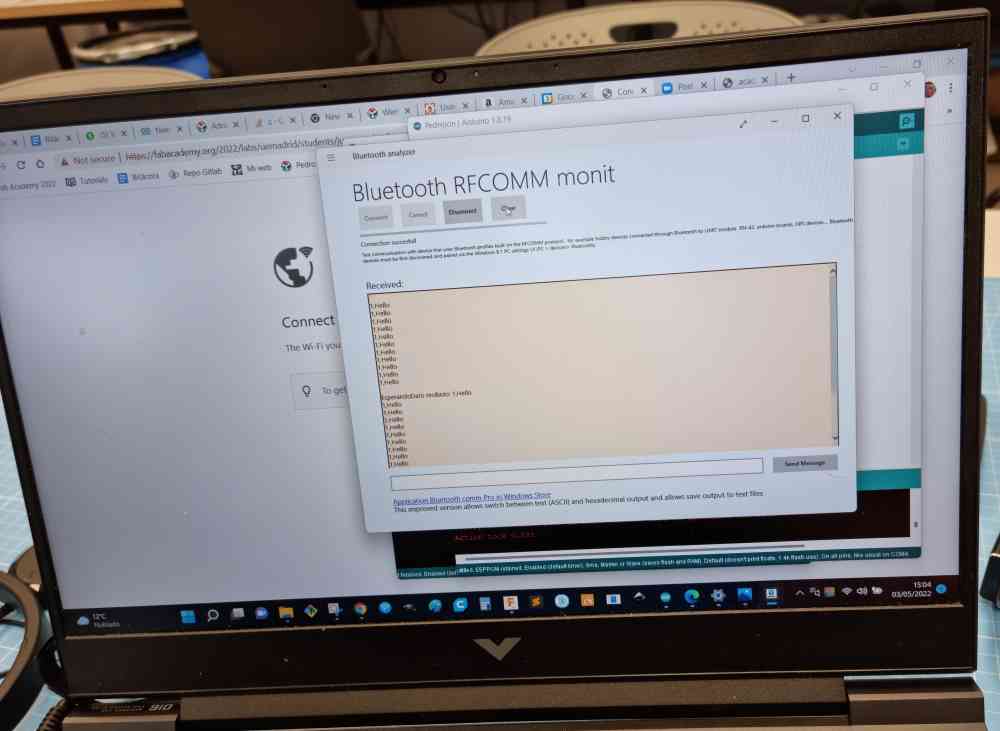
After that you can connect to the device from the Bluetooth Analyzer:
And when you send a message it is sent back by the board via bluetooth:
Learnings from the proccess
1-I learnt how to make an asynchronous I2C communication between different boards, and to manage Bluetooth communications.
2-I learnt how to set a different I2C address on an OLED display, so you can use two of them on the same serial bus.
3-I spent a lot of time trying to communicate with a Bluetooth board that was broken. Same happened to me weeks ago with a broken OLED display. So, if possible, try to have more than one piece of the components and check them.
4-The learning I wrote on the group assignment about the importance of the speed, delay times and busy ports.