WEEK 13: NETWORK AND COMMUNICATIONS
For this week we´re going to start first with the individual assignment, as in the last weeks, so once we´ve got our communications running my "fabmate" Jon Merino and I, will connect and send a message between our projects for the group assignment.
- For the INDIVIDUAL ASSIGNMENT , my planning will be:
- Understand and overview the different types of communications: Wired: Asyncronous and Syncronous and Wireless.
- Design and connect a wired connection.
- Design and connect wireless.
- For the GROUP ASSIGNMENT
- Connect between two projects and send a message.
INDIVIDUAL ASSIGNMENT
This week´s feels like going again to a long steep learning curve. As there´s a lot of communication concepts to understand, and a lot of arduino IDE code to comprehend before starting to design and connect our project. So, as in the first weeks I take my time in reading and reviewing useful webpages and other promotions repo´s, such as Adrián´s Network and communcations, Serial Peripheral Interface (SPI) and Jofin I2C protocol explanation as a starter.
WIRED: Asyncronous
UART: TX-RX
In an asyncronous network communication, there´s no global clock, and communication is made trough Tx - Rx. For this wired connection, we will have a bridge board and nodes, and you´ll need to assign ID´s to each node. Each node has an identity (ID), they´re serialized. So, when it´s called by the host(brige board) it transmits.
- BRIDGE: Connected via FTDI or UPDI. Nodes are connected to it. And it´s used to see or to send values.
- NODES: Connected by BUS or pins. Contains a module. You have to program it so when called (brigde board), it does "something".
To transmit, all the nodes will be connected to the bridge board by bus, with the following connections (Tx, Rx, VCC and Ground). Regarding Tx and Rx, the microprocessor will connect with the bus as usual Tx-Rx, but the nodes will connect Tx-Tx and Rx-Rx.
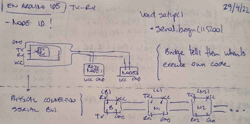 diagram
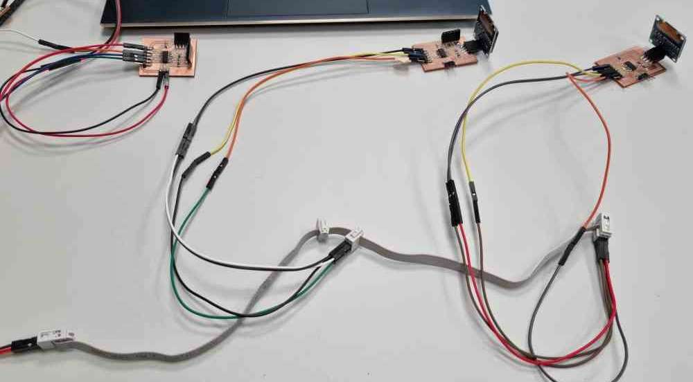 bride + nodes
In ortder to achieve it, I used three ATtiny 1614 boards previously made in Output and Input assigments, also used two Oled display modules for each of the nodes, a 4 pin bus connector, and dupont cables.
The schematic used, as you can see in the image above, was a brigde module powered by a serial UPDI + VCC, and connecting Tx, Rx, VCC and Ground trhough the 4pin bus connector. It´s good to remind that in the bridge, Tx is connected to Rx, and viceversa, to ensure a proper communication between the peripherals and the main board (bridge), but all nodes will connect Tx to Tx, and Rx to Rx as they´re serialized.
 Bridge connections.
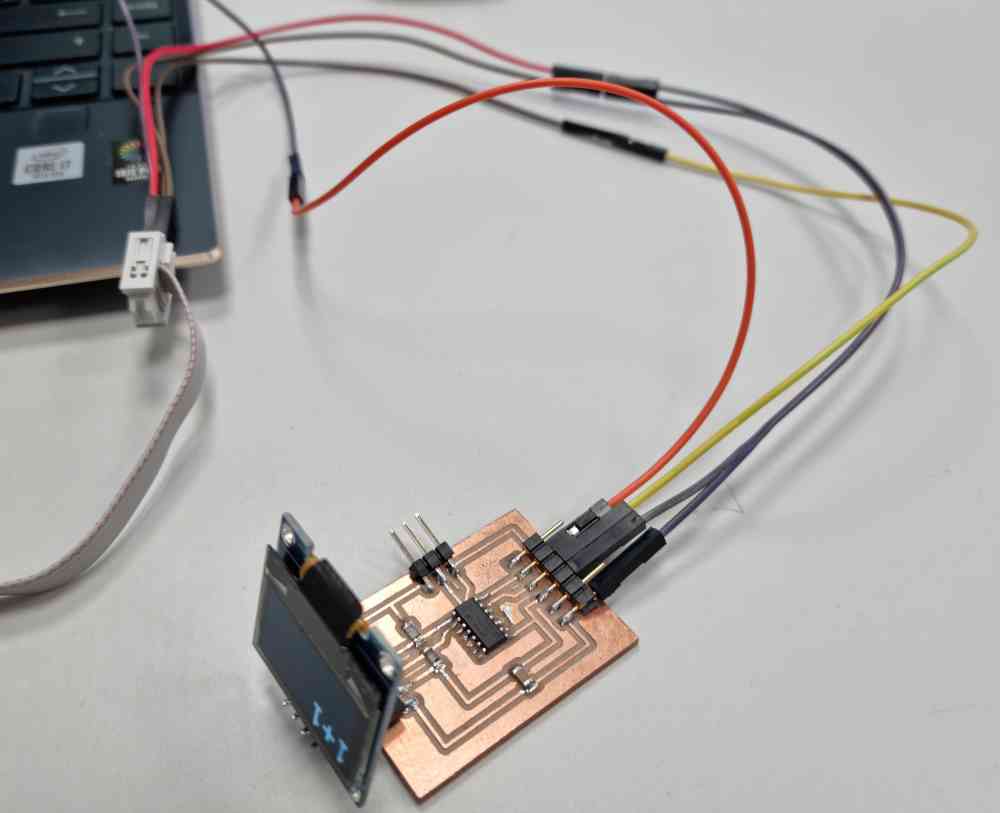 Node connections
Once the hardware connections were made, I used arduino IDE to program the BRIDGE first and the nodes after. To program the bridge I firts reviewed some documentation, such as Adrián`s output assignment. I used Adrián´s code structure but as you can appreciate I made substancial changes, adapting the code to my needs.
Here you can check the steps made in the bridge`s Arduino IDE code, and it´s structure:
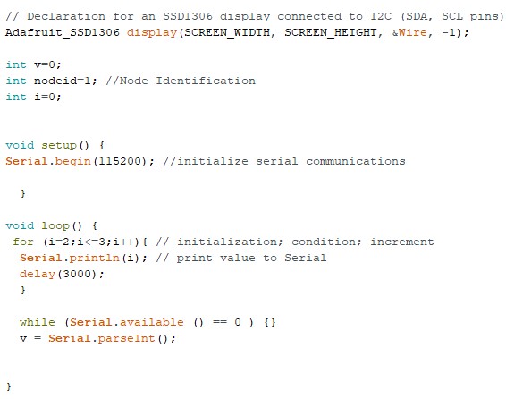
| First declare node identification. |
| In void setup: Initialized serial communications (Serial.begin(115000)). |
| Void loop: Change from node to node, with a 3 seconds delay. |
Bridge code
Download .ino file: Arduino IDE code for the bridge.
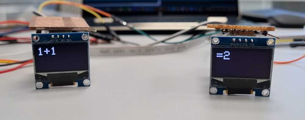
To program the Nodes, The aim was when each board is called it has to "print" in the Oled display: 1+1, and when not, display: = 2. So, eventually, both node codes are similar with just a unique change, they have different node identifications:
- Node 1: nodeid=2
- Node 2: nodeid=3
Here you can check the steps made, in the Arduino IDE code, for the nodes:
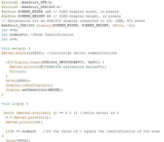
| Include the libraries needed: Adafruit GFX and SSD1306. |
| Define Oled display screen. |
| Declare node identification: In this case one node will be (nodeid=2) and the other (nodeid=3). |
| In void setup: Initialize serial communications and Oled display. |
| In void loop: code what is the node going to "do" when called. In our program, when called it will print "1+1", and else it will print "=2". |
Node code
Download .ino file: Arduino IDE code for the nodes.
Once everything was ready, I uploaded the bridge and the nodes code following the same proccedure as in Output devices. Were I used the megaTinyCore board manager, selected the ATtiny1614 proccesor and a Serial-UPDI fast programmer.
Here you can check how it went:
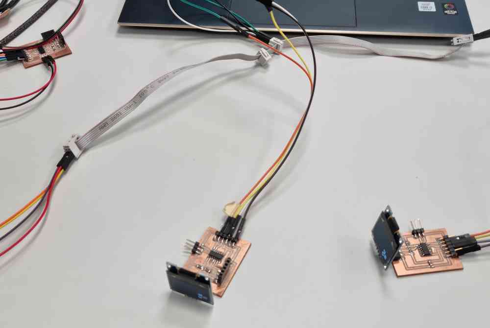 Network.
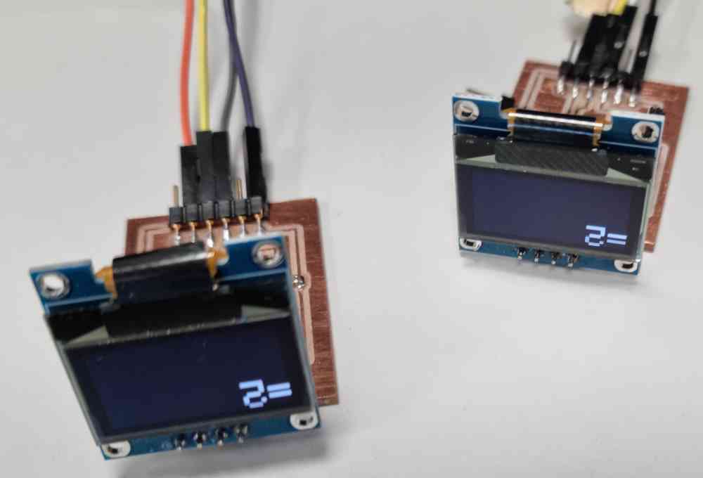
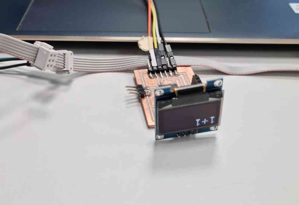 Node "called".
WIRED: Syncronous
I2C
As usual, I deep into the I2C concept in order to understand it, as it might be the communication I could use for my final project. I read thoroughly this complete documentation for newbies from instructables and extract the first concept ideas:
| I2C: Two-wire syncronous serial bus -> SDA(serial data) and SCL(serial clock). |
| You need: Master and slave modules, arduino IDE code with Wire library.. |
| Syncronous: Data is syncronized via clock signal, generated by the master. |
| Serial: Data is transfered serially. One single bit is transfered at a time over a single wire. |
| Bus: A system that allows many devices to communicate to each other over a single set of wires. It allows new devices to be added simply, and each device has a unique adress. |
| Master: Initiates connections, and slave must wait for a master to address it before it sends or recieves anything. The master provides the clock signal and the transfer (send or recieve) will continue until the master sends a stop condition. |
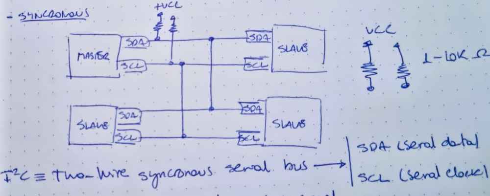 I2C Communication schematic.
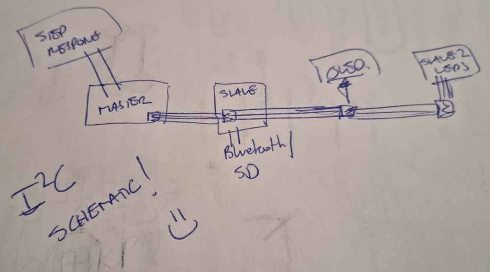
Once I have the basic concepts reviewed, it´s time to design a possible schematic amd investigate how to code it!
I wan´t to test how part of my final project would connect, so I roughly design a Master board connected to a step response (Tx-Rx), that will give an input, and this master board will communicate (send info to slaves) with two slave boards (one for SD data saving, and another for led activation) and directly to an OLED display module all via SDA, SCL.
But, during this week, we learned in the regional review that we don´t have to make a mandatory I2C wired connection, so I´ll jump straight to the wireless connection, as it´s going to be the connection i´m going to use, as it permits me connect to a mobile or a computer with the same settings.
WIRELESS:
After testing wired connections and network, I continued with wireless testing. For my next spiral, I use a HC-06 Bluetooth module, I initially was going to use a HC-05 version but it doesn´t work!
First of all, I reviewed past repositories, such as Ioanna, Tanja and Adrián´s Adrianinos HC-05. To be able to understand some concepts needed, such as connections needed, master/slave connections, Baudrate, adress, pin, ect.
The first test I´m going to do is to read data in my mobile phone, via bluetooth connection. So, in order to achieve it I´m going to use the same board used before, with an ATtiny1614 microcontroller, but this time, i´m going to connect it to the HC-06 Bluetooth module in order to "read" the "strenght" value thats going to come from an analog pin input.
To achieve it, FIRST I programmed the board with arduino IDE code, as before, with an own prepared code with the serial UPDI (same proccedure as in the wired connections). Once I succesfully programed it, I didn´t have issues, I connected my HC-06 to the board, using the same pins as the FTDI connector, so I wouldn´t have problems regarding Tx and Rx pin reading. And FINALLY, to power it up, I used the serial UPDI Ground and VCC. So, here´s how it went:
Download .ino file: Arduino IDE Bluetooth code.
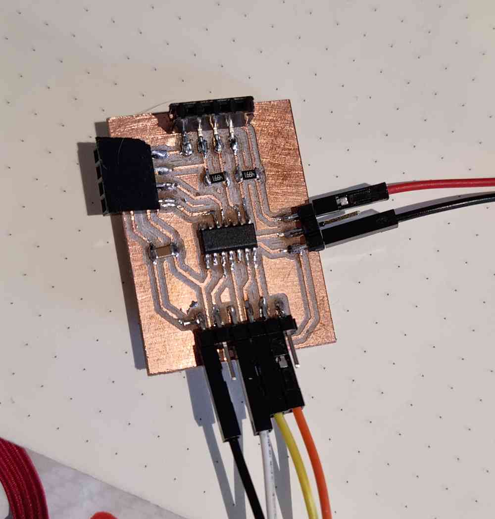 ATTiny1614 connected to VCC, GND and HC-06.
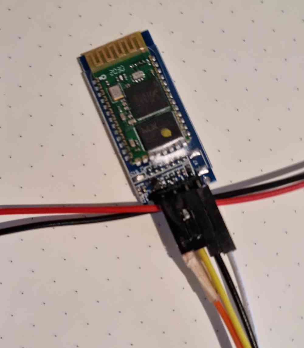 HC-06.
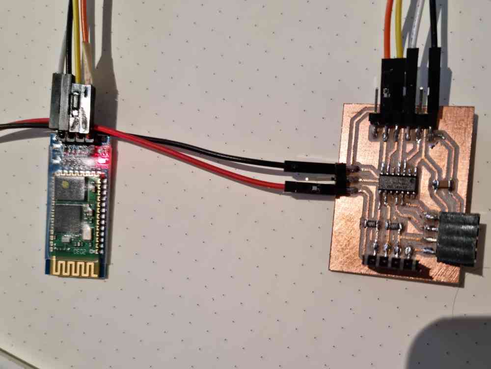 Both modules.
Once I had it connected and running, I installed the Arduino Bluetooth Controller App from the playstore for Android, connected my mobile phone to my bluetooth module, opened the Terminal mode, and succesfully visualized the incoming data from my board!
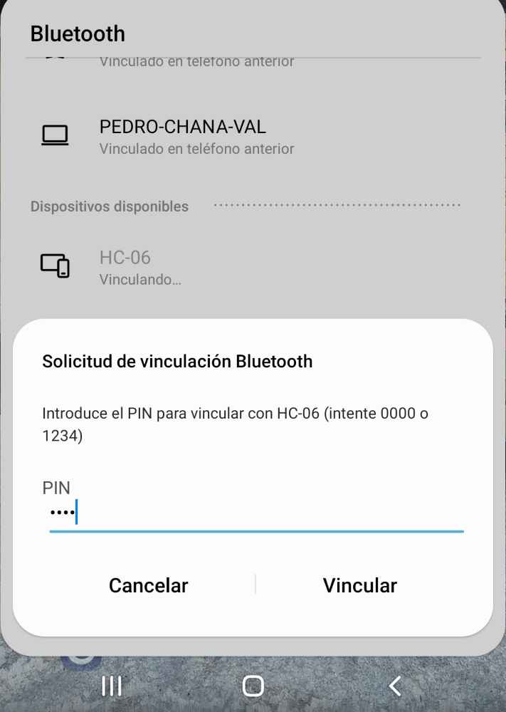 Coonecting HC-06 to phone.
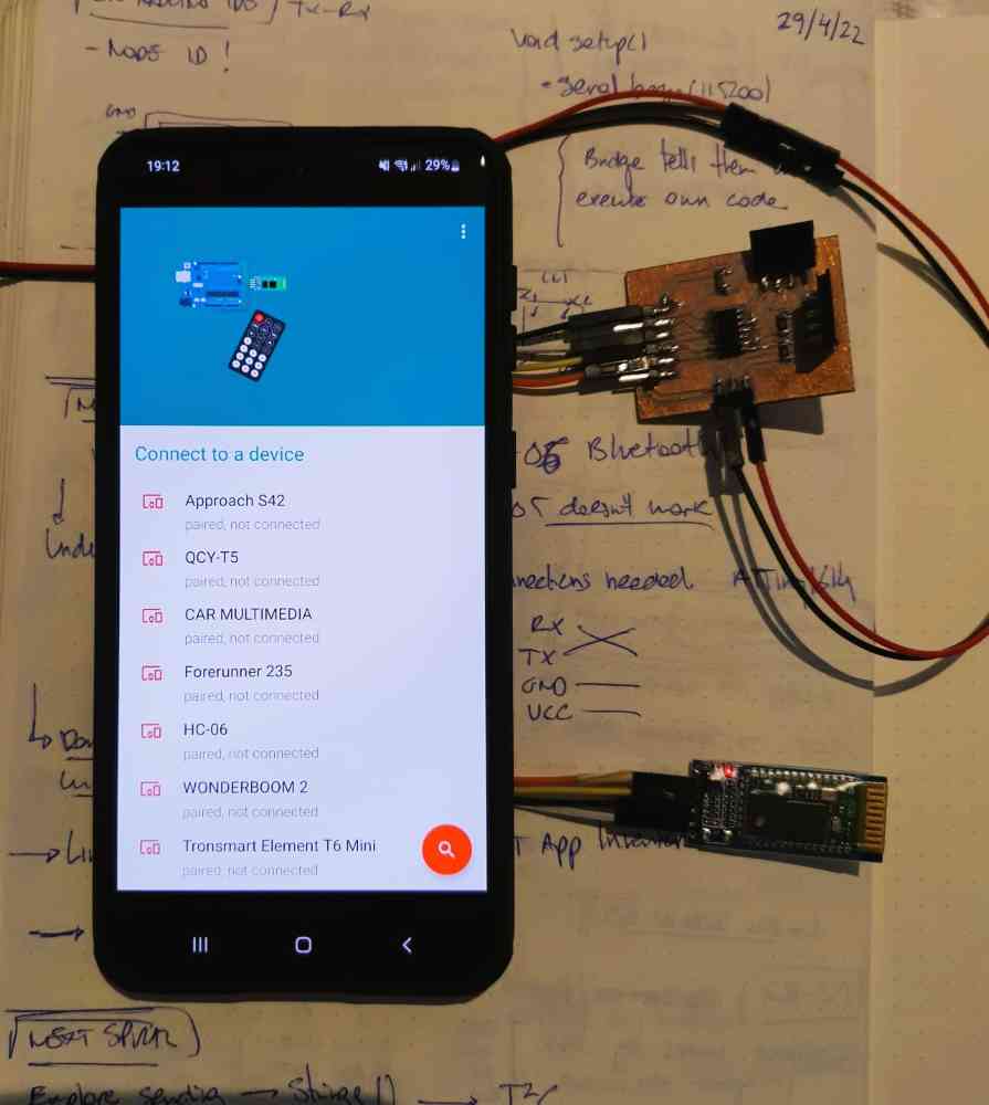
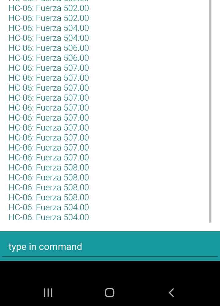 Reading data.
Here below you can see a video of how it works, but without the force sensor:
As for how it´s going, this week is a tricky one, it´s seems that we´ve had "little" to do.. but it´s probably one of the assignments were I invested more time in understanding all the possible ways to communicate, ISP, Tx-Rx, I2C, WIRELESS (Master and slave), etc. The good part is that i´ve managed to complete my goals, even do I would have spent way much time testing, and what it took me more time at the end wasn´t to understand or hardware connect the network.., but to undestand and learn all the different arduino code settings that´s behind it! But, as i´ve said, happy with the learning curve and wishing to have more time to keep on testing.
GROUP ASSIGNMENT
For the group assignment Jon and I decided to communicate, vía Tx-Rx, assyncronous network, one of my boards (an ATtiny1614) as the bridge, with one of Jon´s boards (Another ATtiny1614) as the node, which is also connected to an HC-06 bluetooth module. So the communication will go as follows:
| Network: Tx-Rx. Brige -> Node. |
| Brigde: Communicates with node, and sends a "Hello" message vía Serial. |
| Node: When node called, runs the code programmed -> Recieve "Hello" message from Serial and send it to a computer vía Bluetooth. |
| Computer: Linked to Bluetooth, receives the "Hello" message from the node. |
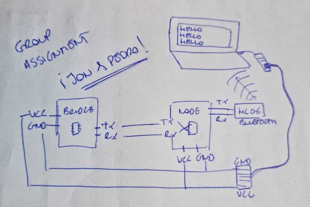 Network schematic.
To prepare the "hardware" connections, we used a Tx-Rx connection between the bridge and the node, and the bridge got VCC and GND from it´s own UPDI serial + VCC. The Node, apart of being connected to the brige and having it´s own GND and VCC power connection, from another UPDI serial + VCC, it had also a Tx-Rx connection to an HC-06 Bluetooth module. And the Bluetooth module, was paired to a laptop, where we could see what was being sent.
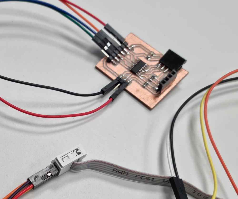
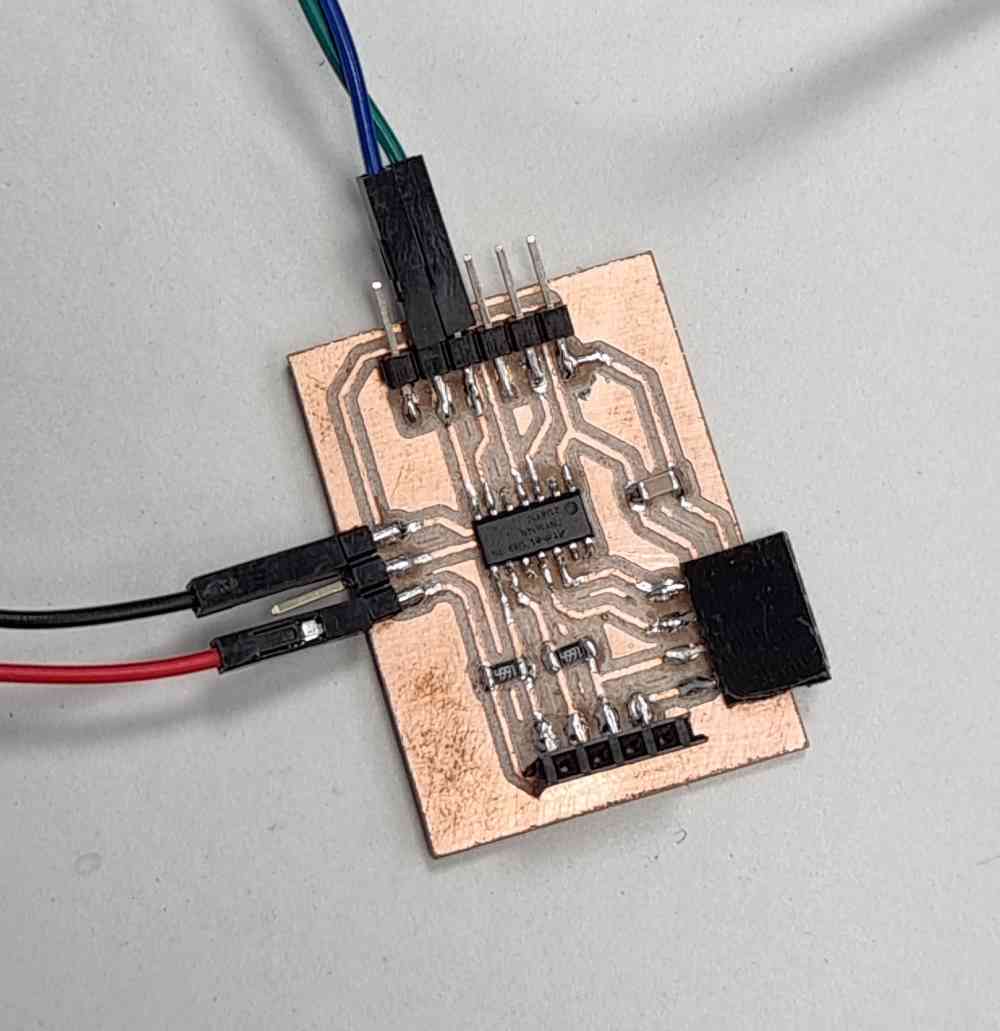 Pedro´s bridge board.
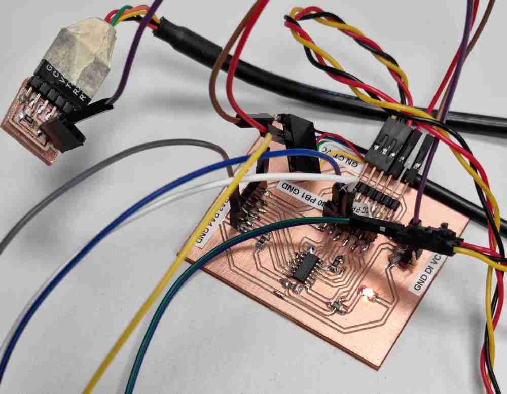 Jon´s node board + serial UPDI +VCC.
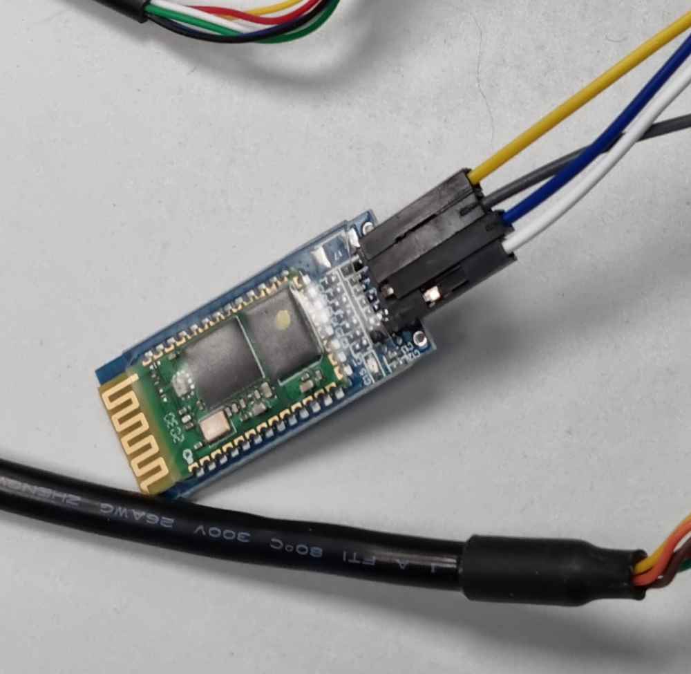 HC-06 Bluetooth module.
To prepare the "software" coding, we coded first, with arduino IDE, the brige program using the same proccedure as the individual assignment. But this time with only one address and with the aim of sending trough the serial a "Hello" message.
Download .ino file: Bridge Tx-Rx Hello code.
For the Node, we programed it to send the "Hello" message form the serial, and if there´s no serial communication, to print "waiting". And that´s what it´s going to be sent via bluetooth and visualized, in our case, in the laptop.
Download .ino file: Node Tx-Rx Hello code.
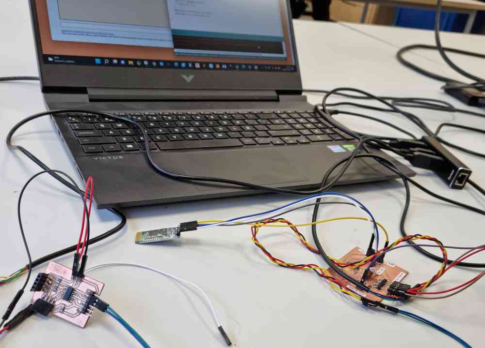 Connections.
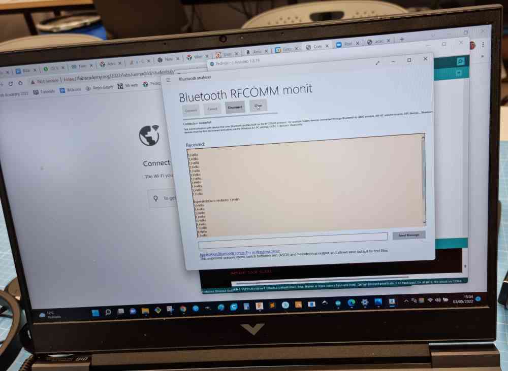 laptop data reading.
Here below you can see a video of how it went:
