4. Computer Controlled Cutting
For this week’s assignment we were tasked with designing in CAD software to create a design with slots that could be laser cut. We also had a group assignment which required us to look at the Laser cutter in our Fab Lab and go through its capabilities. Another task was to create a design that could be cut in a vinyl cutter.
Group Assignment
For this week’s assignment we looked at the epilog fusion laser cutter, its various features and operations for the successful completion of projects. The group assignment can be found using the link below:
Laser Cut Design
For this task I decided to use Fusion 360 to create my design.
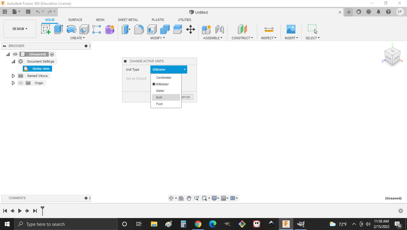
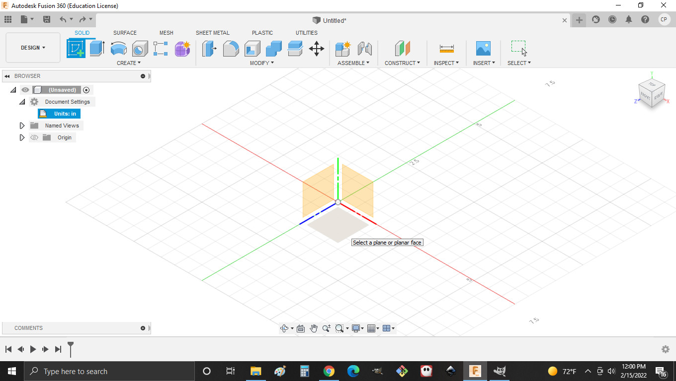
1.The first thing I did was change my units
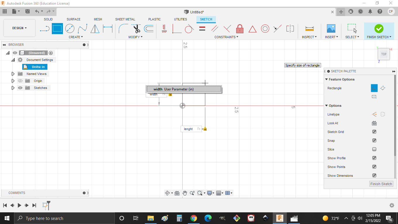
2.Then I created my parameters.
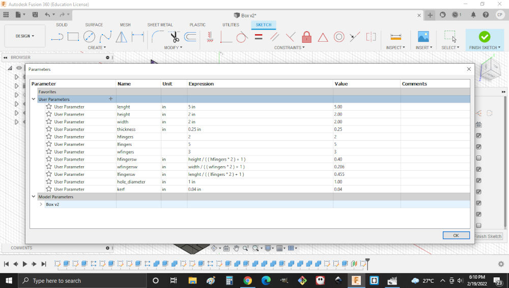
Note. Some parameters may just be values without units
3.Then I created a sketch of a rectangle on the top plane with the parameters I created.
4.Then I extruded the rectangle to the thickness parameter I created.
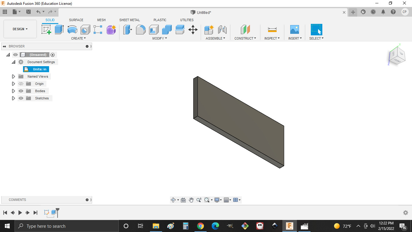 Note. Thickness represents material thickness
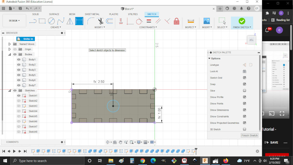
5.Then I created a sketch of a rectangle on the bottom top face and added dimensions.

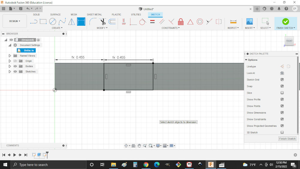 Note. The dimentions from parameters.
6.Then I extruded the rectangle to a depth of the thickness parameter.
7.Then a rectangular array was performed using the feature that was created from the previous extrude.
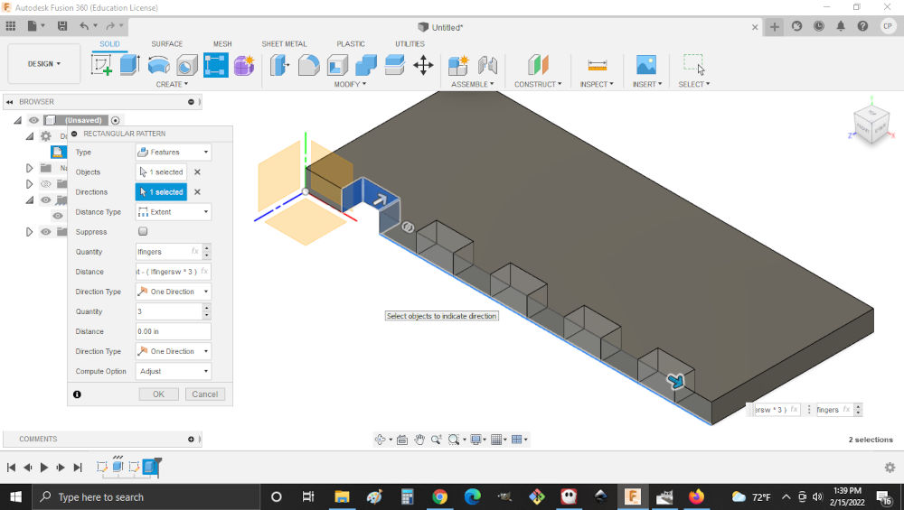
Note.Ensue that you choose the right direction and select the object to array.
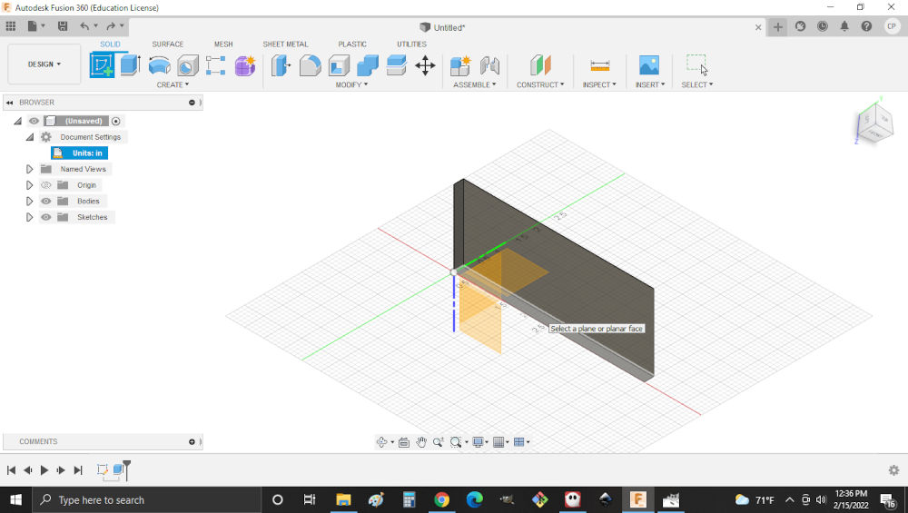
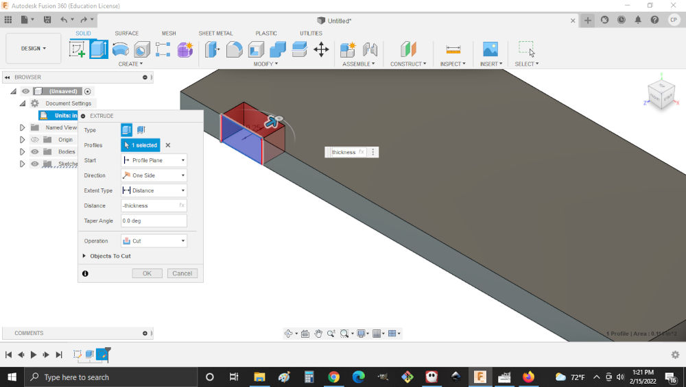
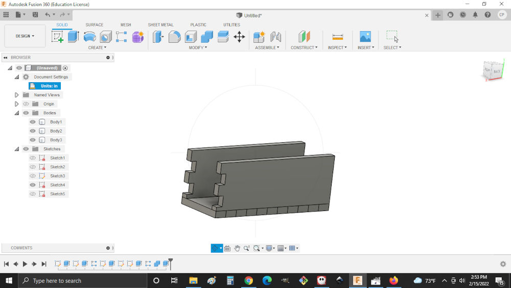
8.Then to create one of the side walls I created a sketch on face with the cut outs and set the length and height to my parameters. I then extruded the new sketch into a new body in the direction of the cut out.
Note. Ensure that the correct points are selected to match the first and created body.
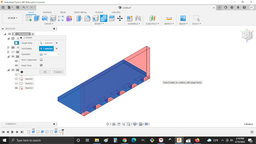
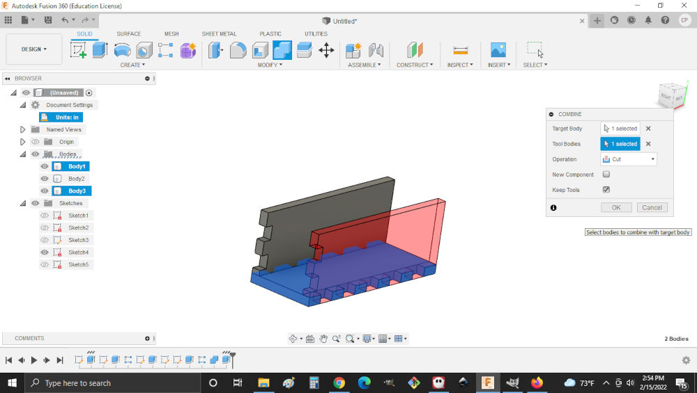
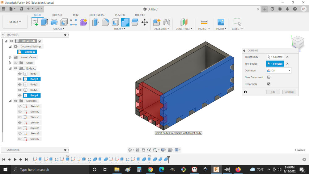
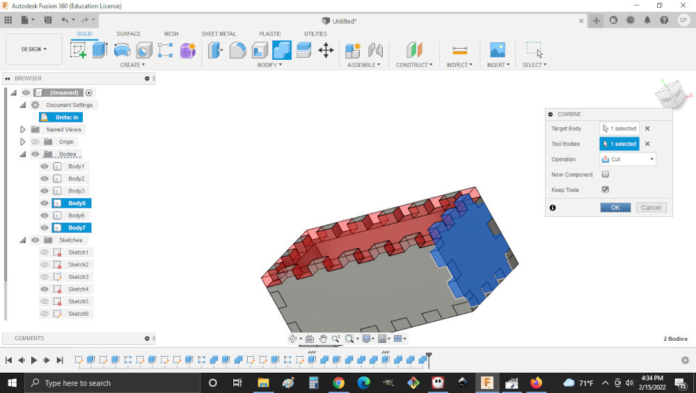
9.Then to remove any interferance between both body’s, I combined them and set the operation to cut while also keeping the tool body.
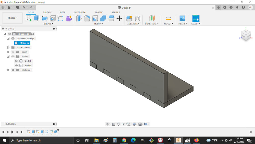
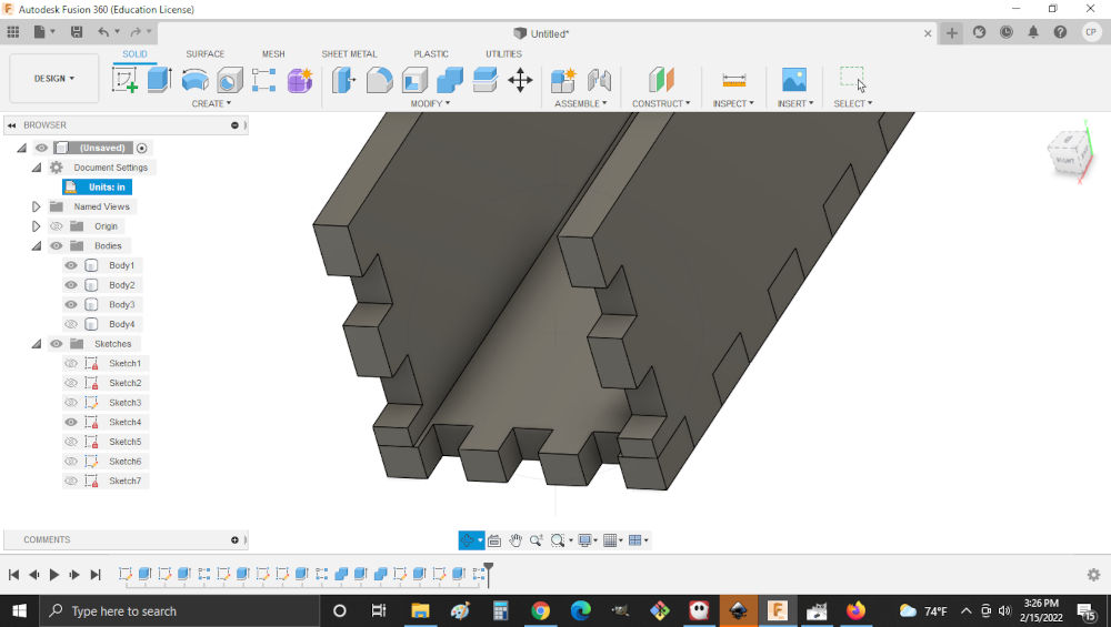
10.Then I repeated steps 5 to 7 on the vertical of the side wall.
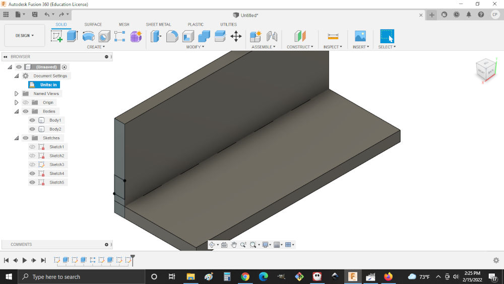
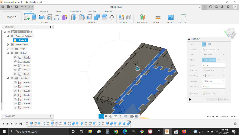
11.Now that one sidewall was completed, I performed another extrusion ensuring that the inner face was selected and start was from object.Then I ensured that the distance was set to minus thickness and a new body chosen.
12.Then to add the cut out for the base I combined the base with the side wall as the tool and set the operation to cut while also keeping the tool body.
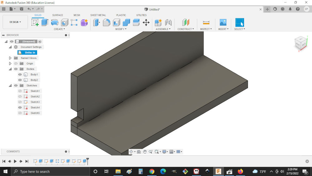
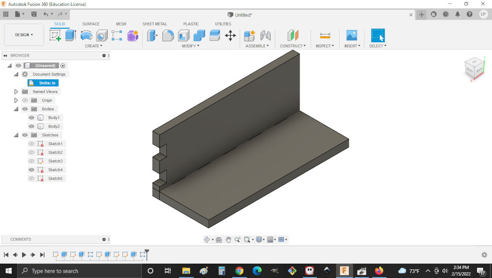
13.Then to create one of the cut outs for the base back I created a sketch on face with the cut outs and set the length and height to my parameters. I then extruded the new sketch into a new body in the direction of the cut out and a rectangular array.
14.Then I created the back wall by drawing a new sketch on the backwall extruding it. Ensuring that direction was correctly seleted and distance set to the thickness parameter The first thing I did was changed my units
15.Then to remove any unwanted material between all body’s, I combined them and set the operation to cut while also keeping the tool body.

16.Now that one backwall was completed, I performed another extrusion ensuring that the inner face was selected and start was from object.Then I ensured that the distance was set to minus thickness and a new body chosen.
17.Then to remove any unwanted material between all body’s , I combined them and set the operation to cut while also keeping the tool body.
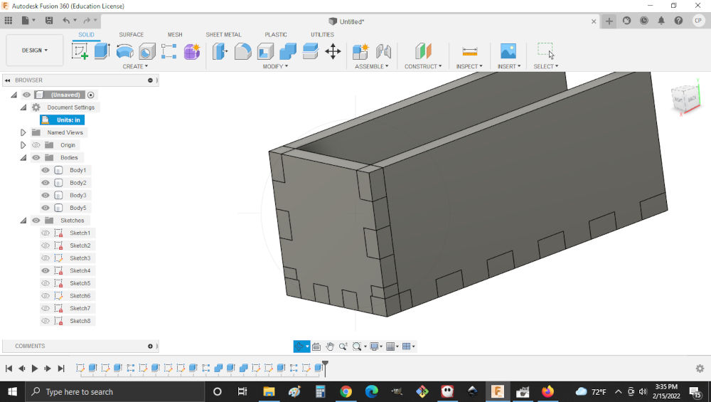
18.Now that all of the walls are created I created the top by extruding the base ensuring that the inner face was selected and start was from object.Then I ensured that the distance was set to minus thickness and a new body chosen.
19.Then to remove any unwanted material between all body’s , I combined them and set the operation to cut while also keeping the tool body.
20.Then , I create a hole at the center of the top of the box by sketch on its face and using parameters to locate the center. After which I extruded the circle to create the hole.

21.Then to ensure the parts accounted for the kerf. I used a plug in found in 360 along with information acquired from the group project to prepare the parts for laser cutting.
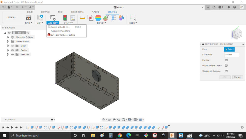
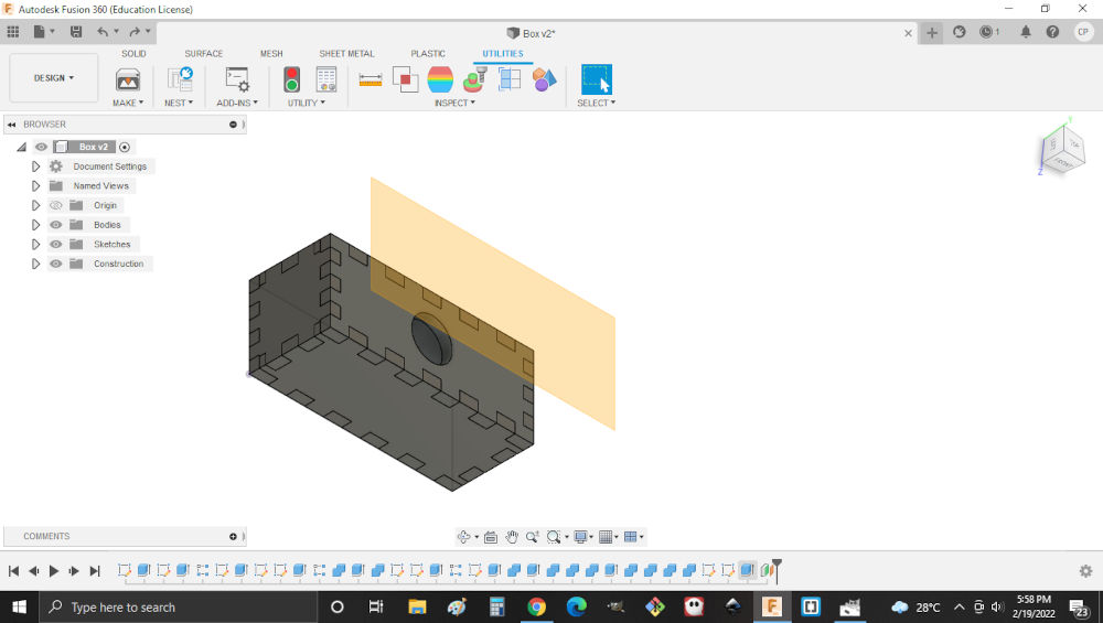
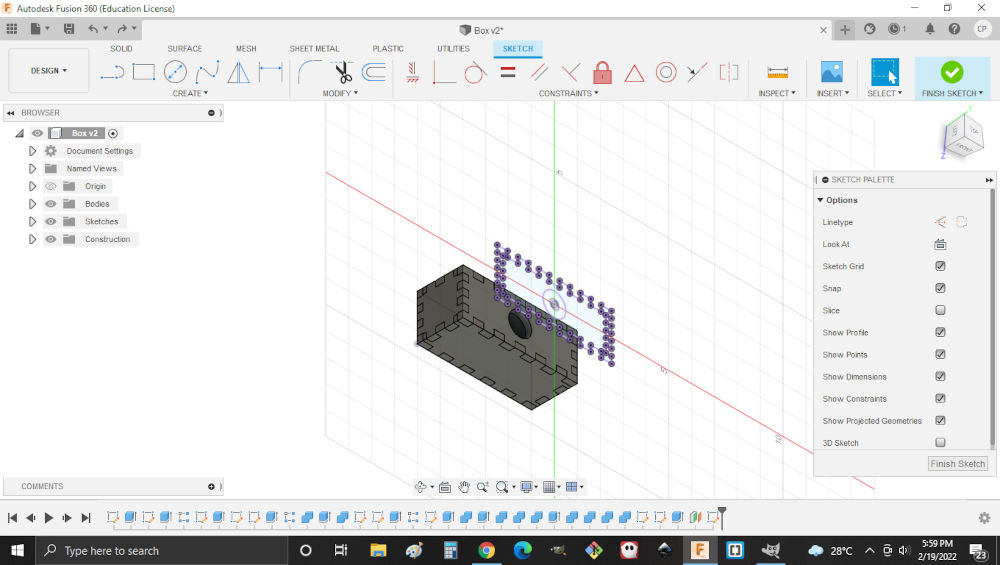
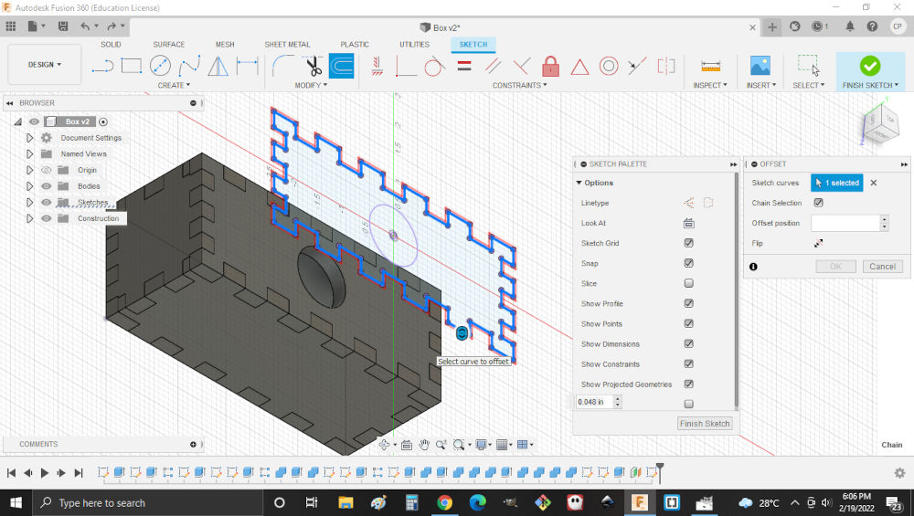
Note. The add in name was dxf for laser.Also note that this can be achieved by creating construction plane. projecting the face of the object and offseting it by the kerf externally to the object.
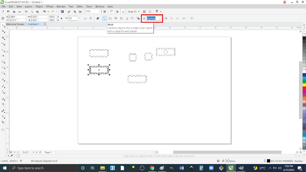
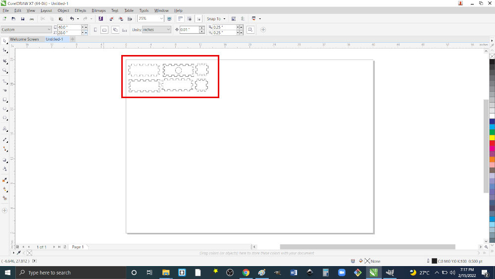
22.After the parts were saved,they were then imported into Corel Draw (software used by the machine) to be prepared for laser cutting. The odjects had to be welded to ensure the laser saw the lines being continuous. The line also had to be hairline to ensure that they would be cut. Lastly the objects had to be placed in a way that reduced wastage.

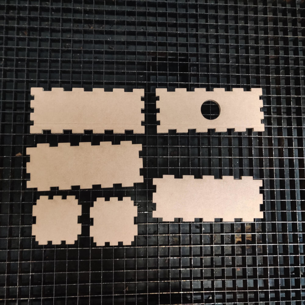
23.After this was done the objects were sent to be printed. At this point the setting were used from the group project for the particular material in this case carboard.
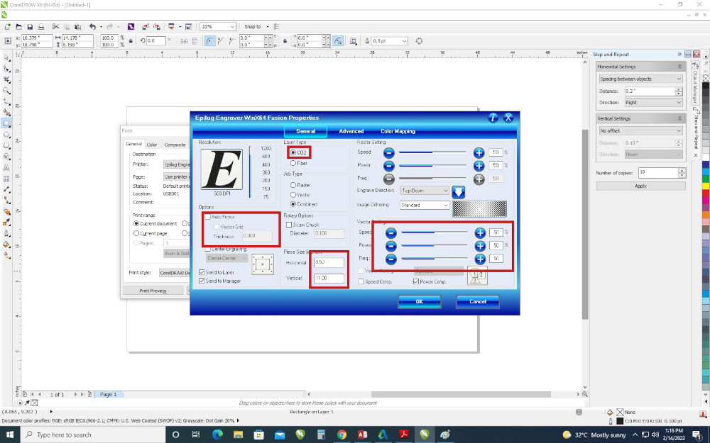
Note.Ensure the correct height of the materialis set to prevent crashes.The vector setting were only used as not engraving was performed.
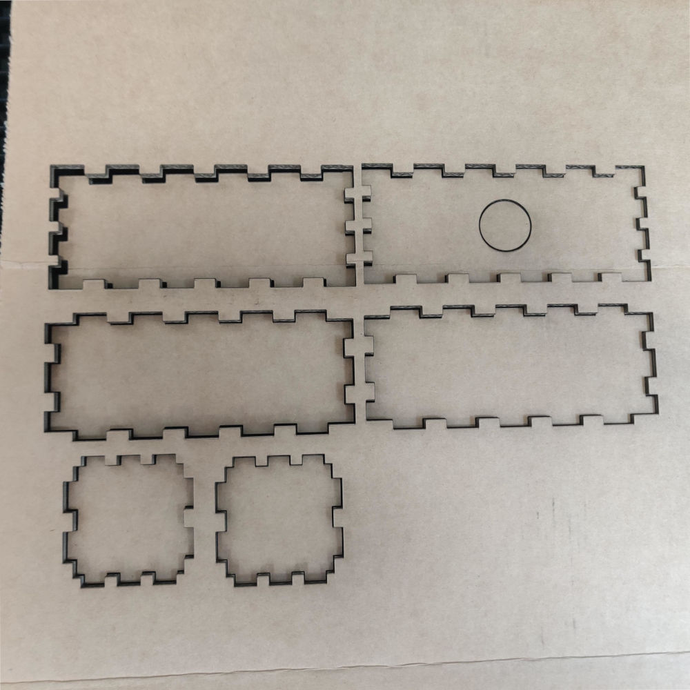
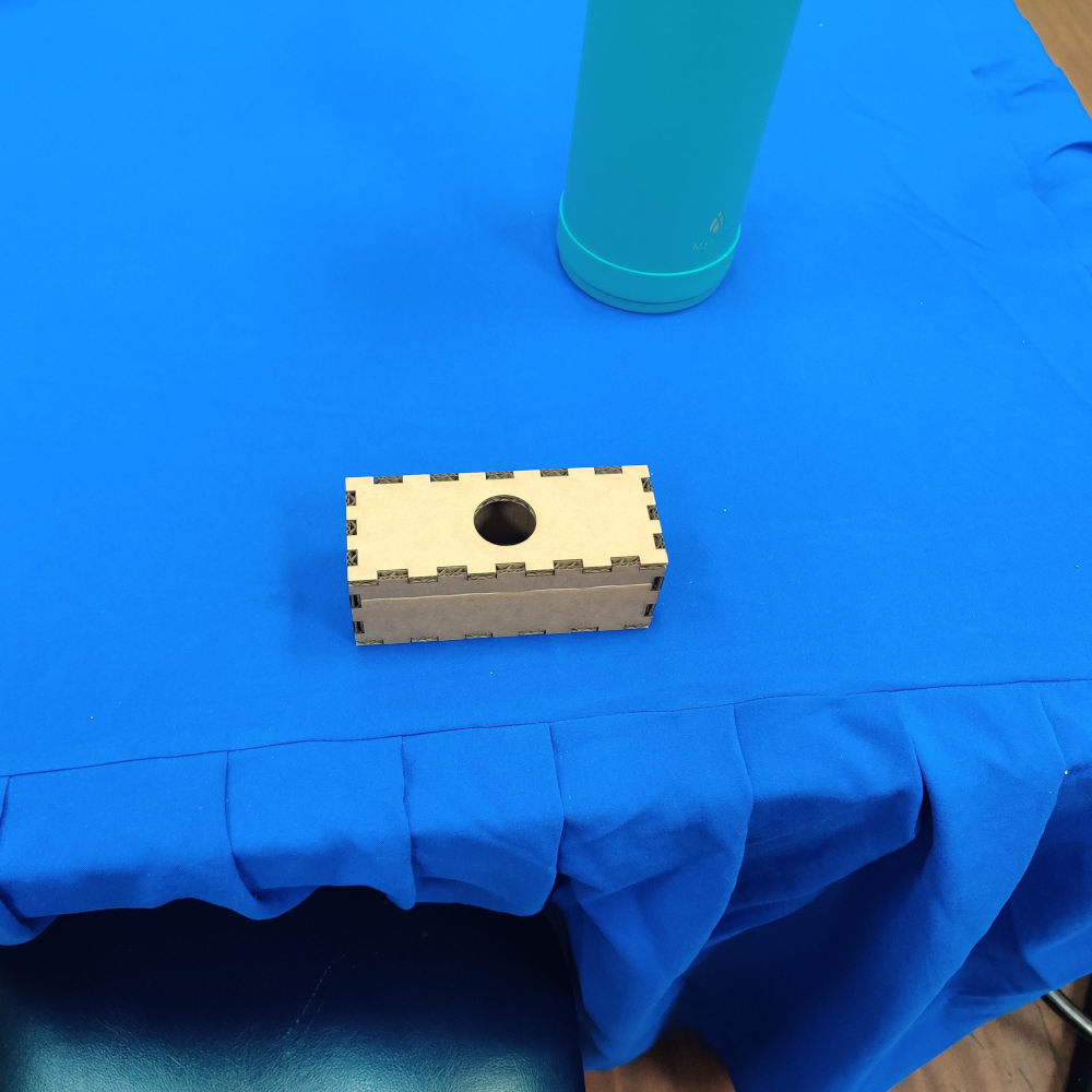
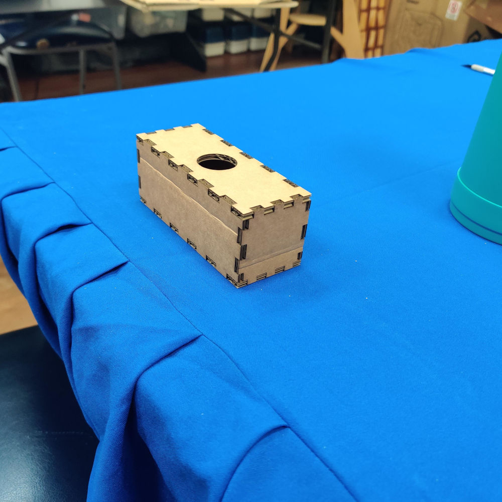
24.After the parts were cut they were assmebled and a photo taken.
Vinyl Cutter
1.The first thing I did was search for an image online, download it and import it to cut studio.
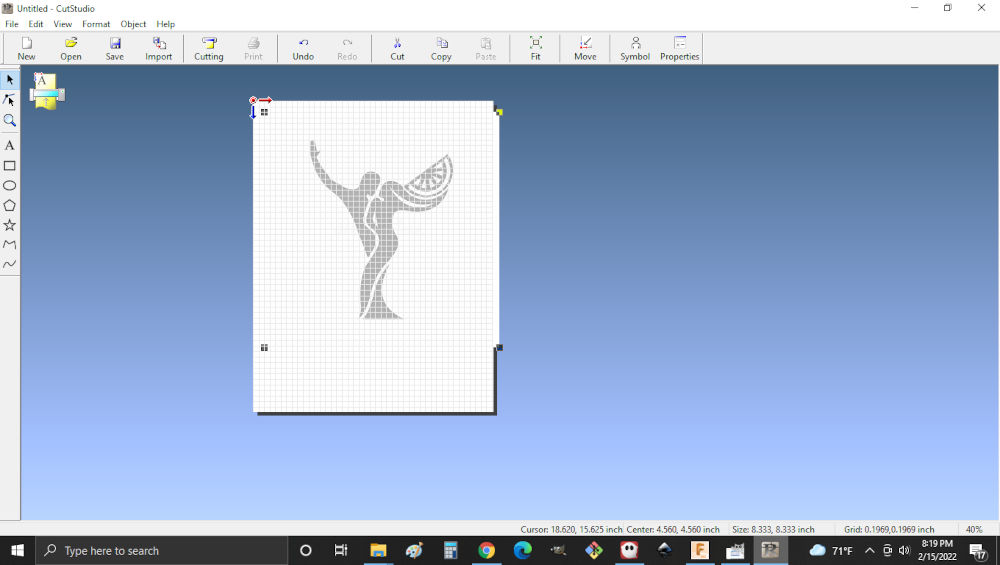 Note.Some formats have issues with cut studio. You can also
2.Then I right clicked on the image to bring up image outline. I adjusted the light and dark settings for the best view of the image and selected ok. first thing I did was changed my units
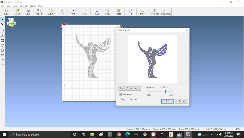
Note. Selecting image outline shows the path of the blade.
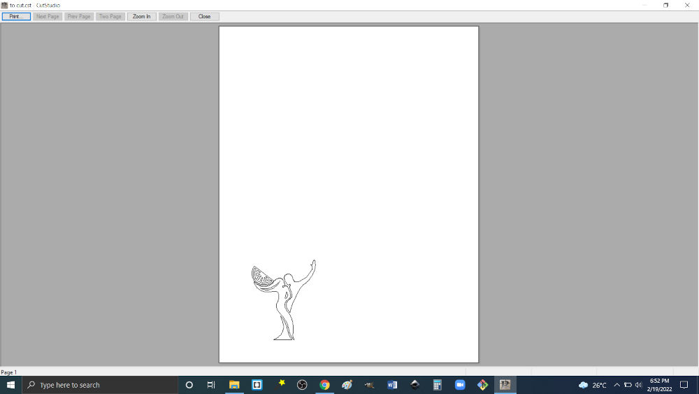
3.At this point you will have two images,one with the original image and the second with edited image to be cut.
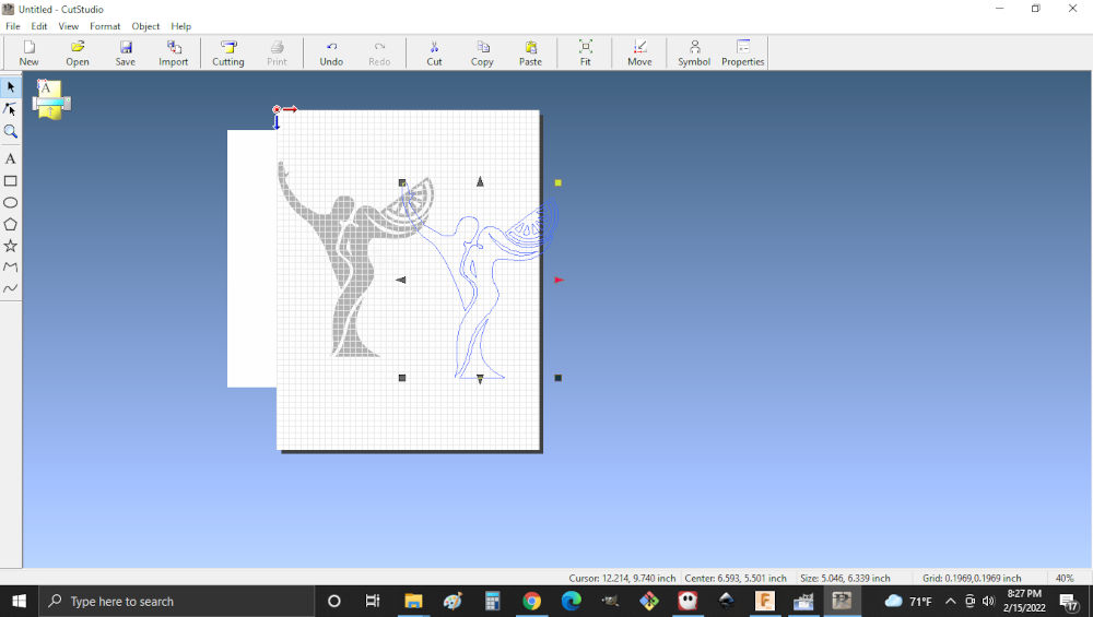
Note. The original image can be removed at this point
4.Then using the handles I resized the image .At the bottom of the screen gives and indication of the image size.
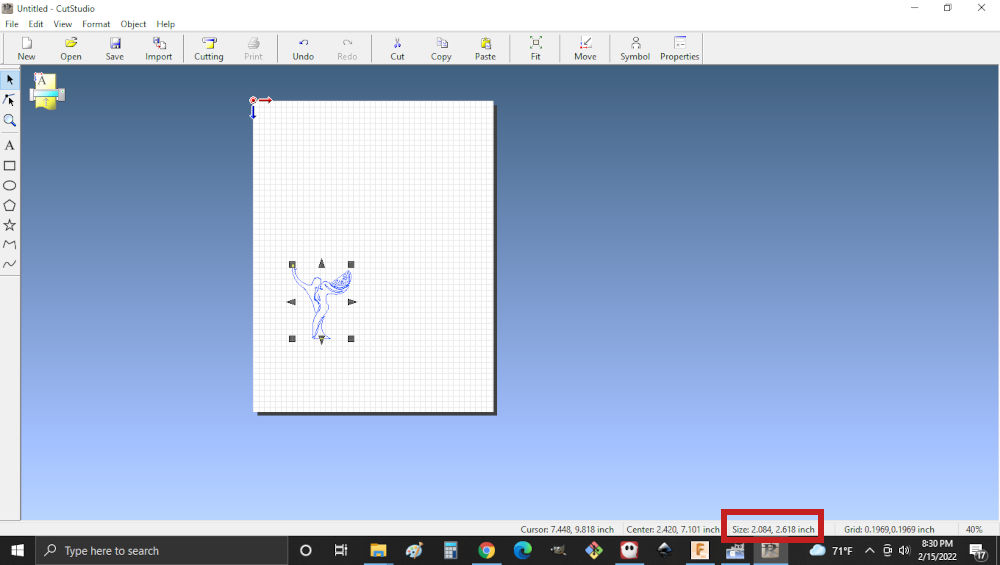
Note.If you require the image to maintain the original shape when resizing hold shift when adjusting the handles.
5.Then I went to cutting setup to ensure I had the correct settings. I selected change media size to set the vinyl size
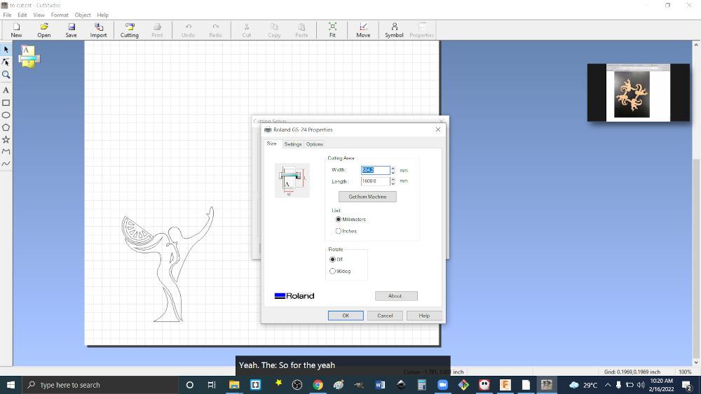
Note. Ensure that the appropriate units are used.
6.Then I mirrored the image by having the object selected and clicking object then mirror.
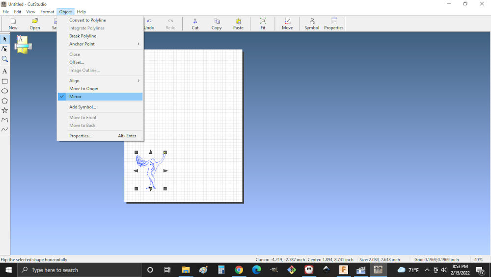
Note.This will ensure that the image is cut in an efficent way.
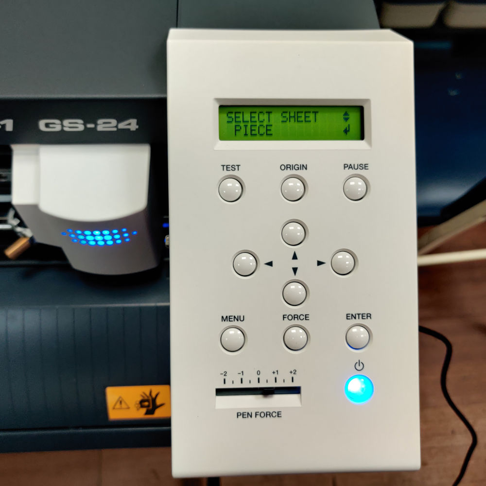
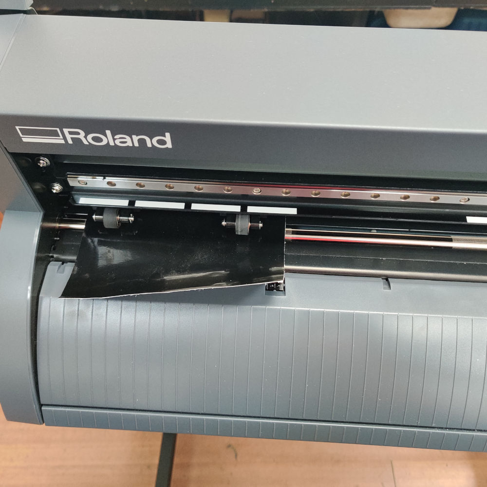
7.The machine was then turned on and material placed in the feeder.
Note. Leave an inch of material on either side of the rollers and use the vertical lines to align the vinyl.
8.Then I selected piece on the machine and select enter so the roland can select the exact measurement.
9.Based on the location of the drawing and the piece mesurement ,I changed the material size to get from machine.I also adjusted the force and speed settings to ensure the image was cut successfully.
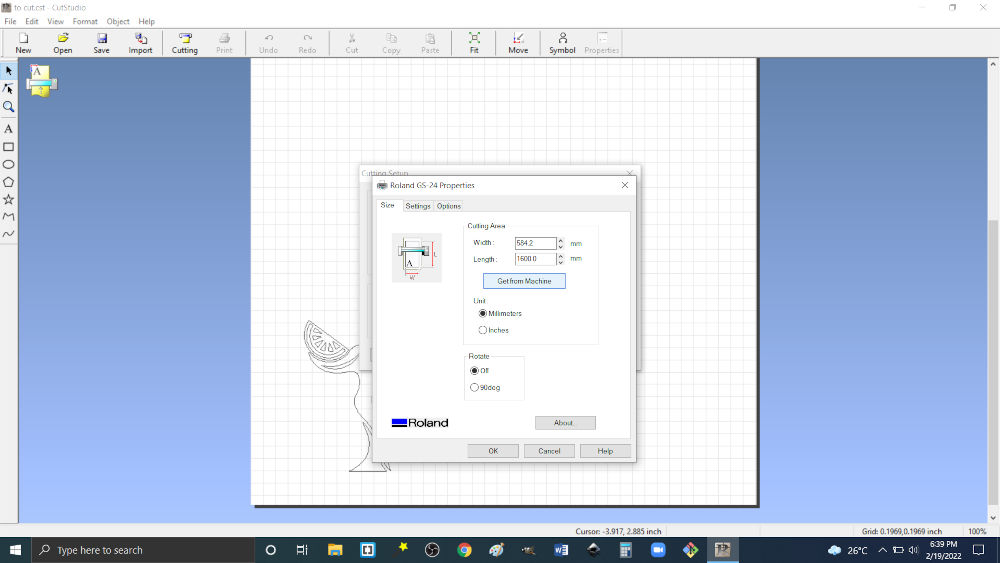
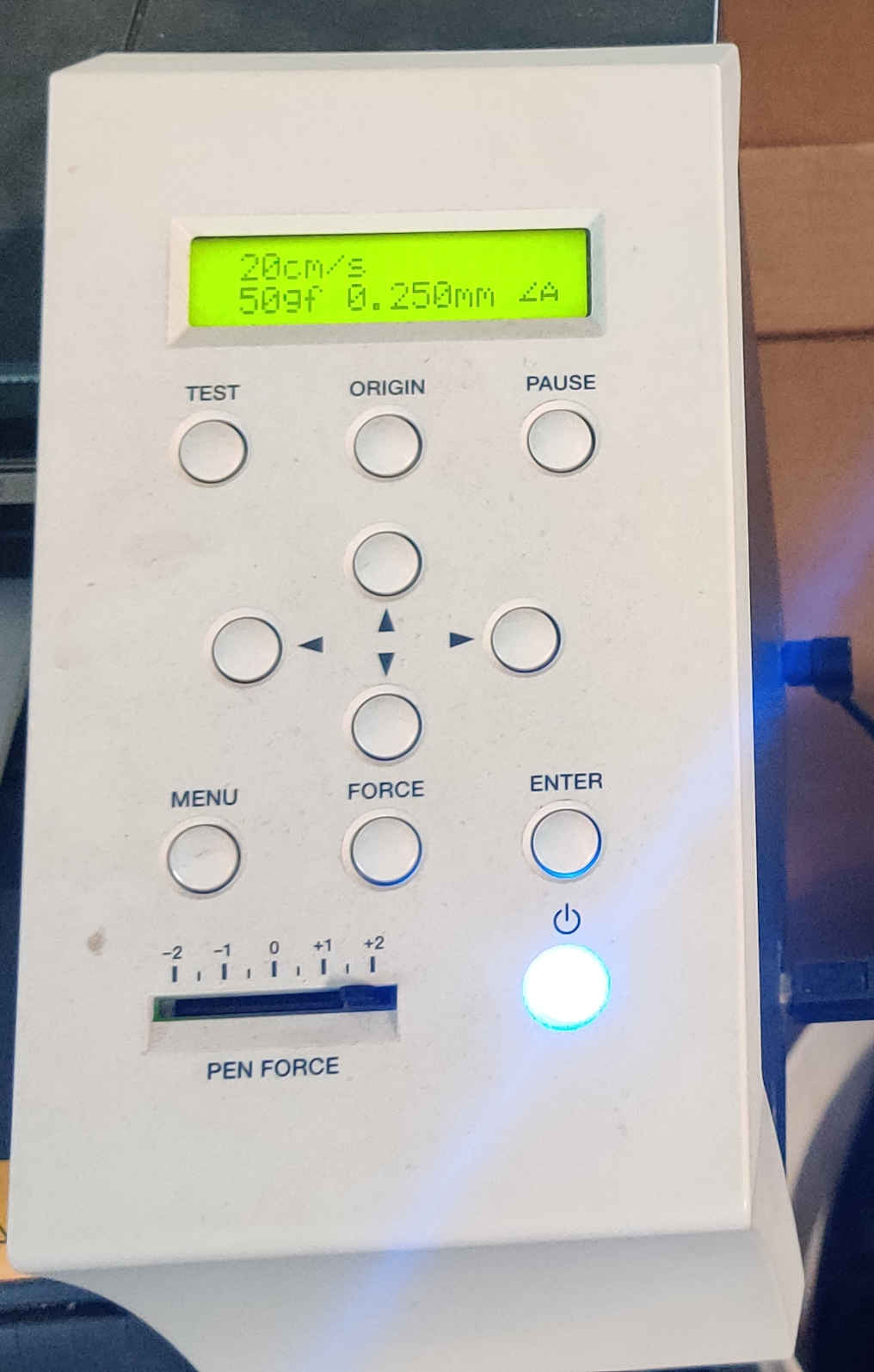
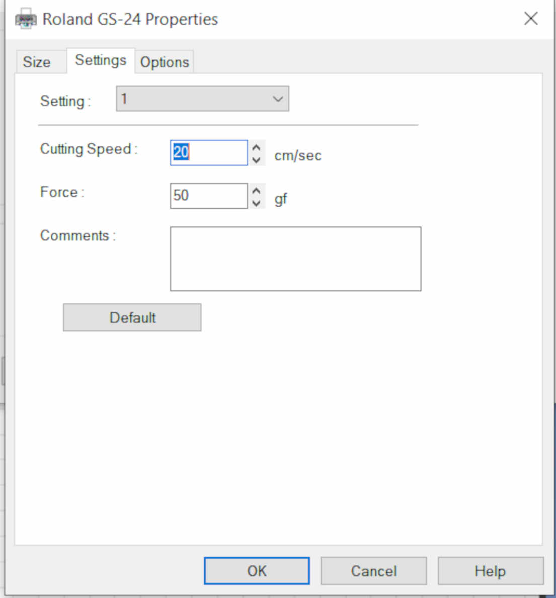
NB. Force mesaured in grams and speed measured in seconds.Also the force and speed can be set from cut settings in cut studio
10.Then I went to cutting and ensured the image was in the cutting area and cut the image.
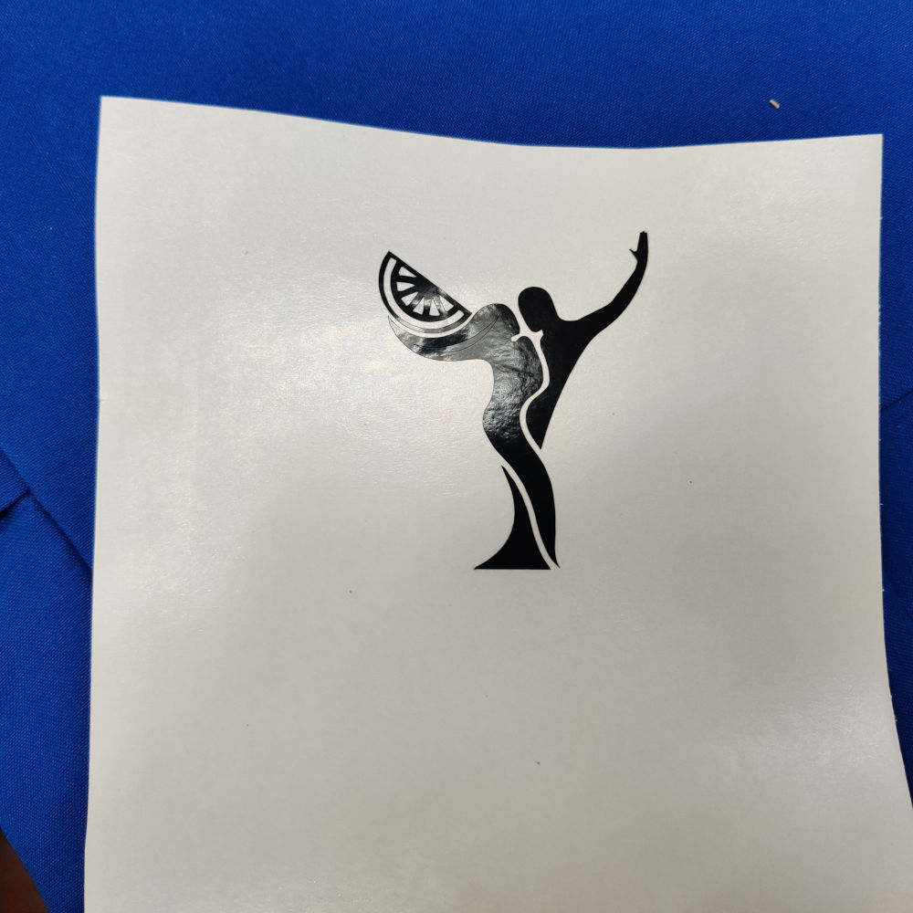
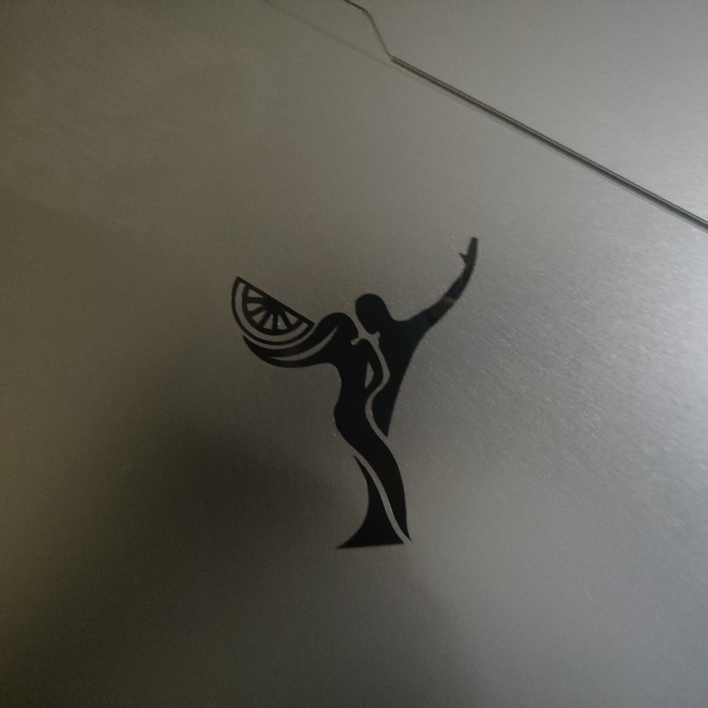
11.After the image was cut, I removed the unwanted material . Then placed it on transfer material and stuck it to a surface.