14. Networking and communications
Embedded networking and communication focuses on the hardware components, communication/data exchange protocols, and network topology and design required to link and connect embedded systems to facilitate data exchange.
Learning outcomes
- Demonstrate workflows used in network design
- Implement and interpret networking protocols and/or communication protocols
Like the previous weeks , student are expected to complete two (2) categories of weekly assignment.
• Group assignment:
- Send a message between two projects
• Individual assignment:
- Design, build, and connect wired or wireless node(s) with network or bus addresses
Group Assignment
For our Group assignment we will need to send a message between any combination of boards. We will need to write code that sends or receives the message in question.
The Group Assignment page is as follows Link
Group Members:
-
Nervene Bhagwandass
-
Christopher Proute
-
Terrence Carew
-
James Khan
-
Marvin Holloway
-
Ravi Baldeo
Individual Assignment
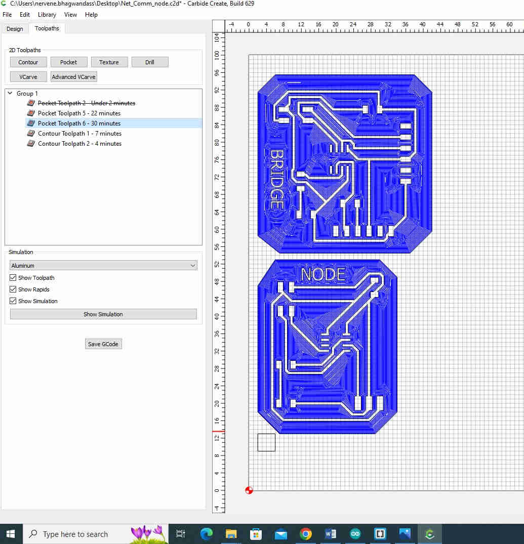
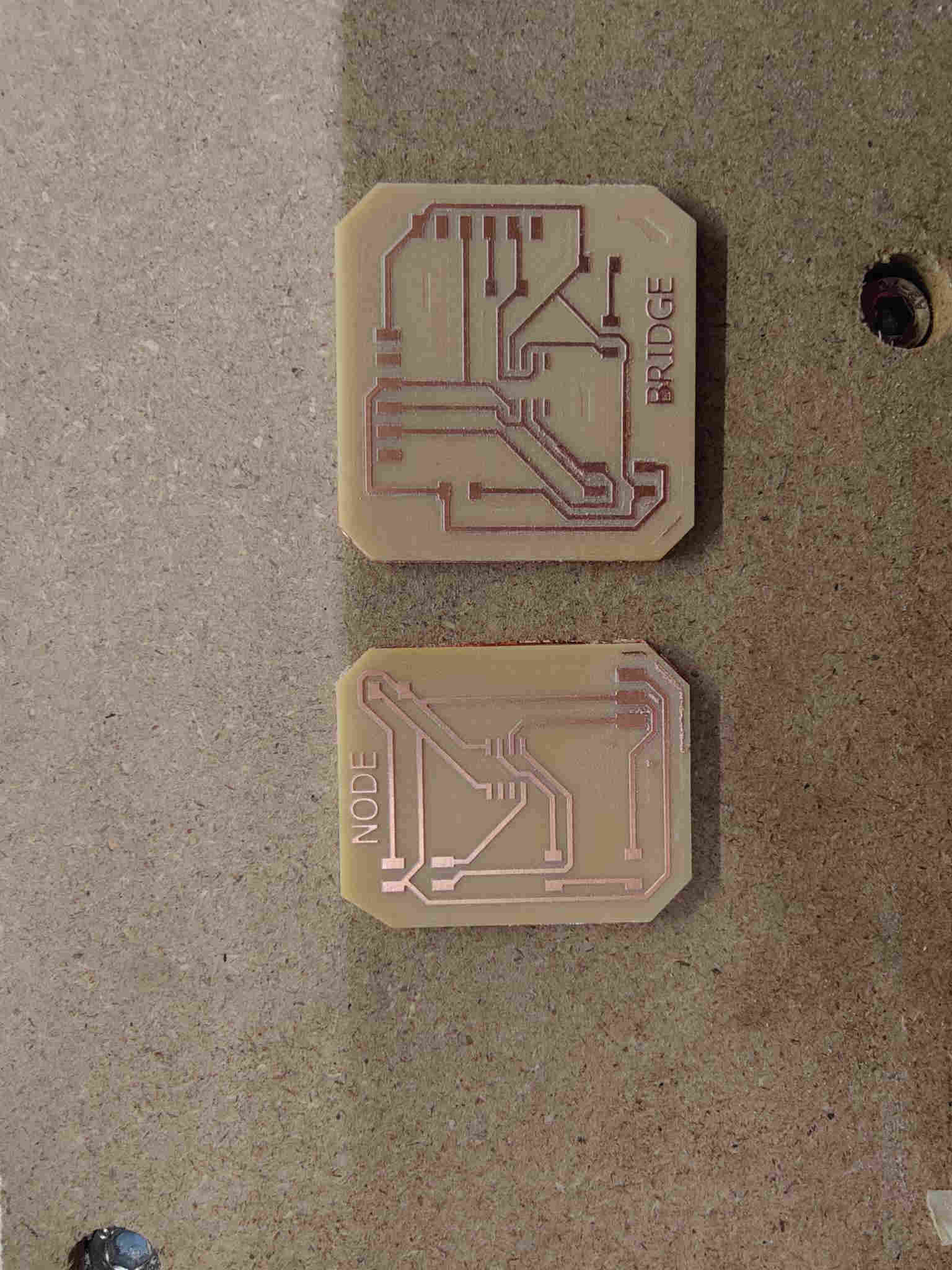
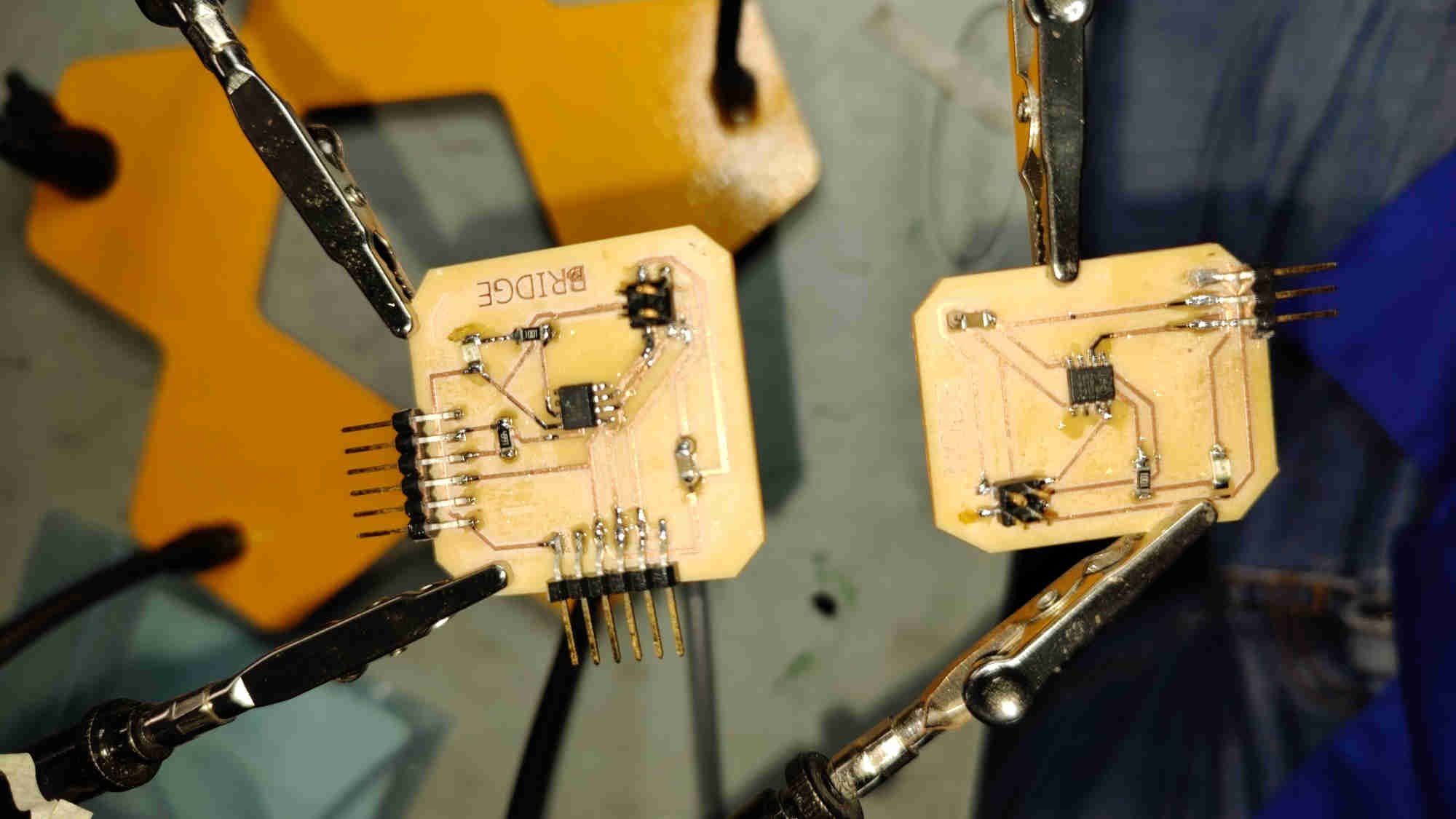
For my individual Assignment for Embedded Networking and Communications, I reviewed Adrian Torres Attiny 412. I designed two boards with of modifications.
-
Bridge
-
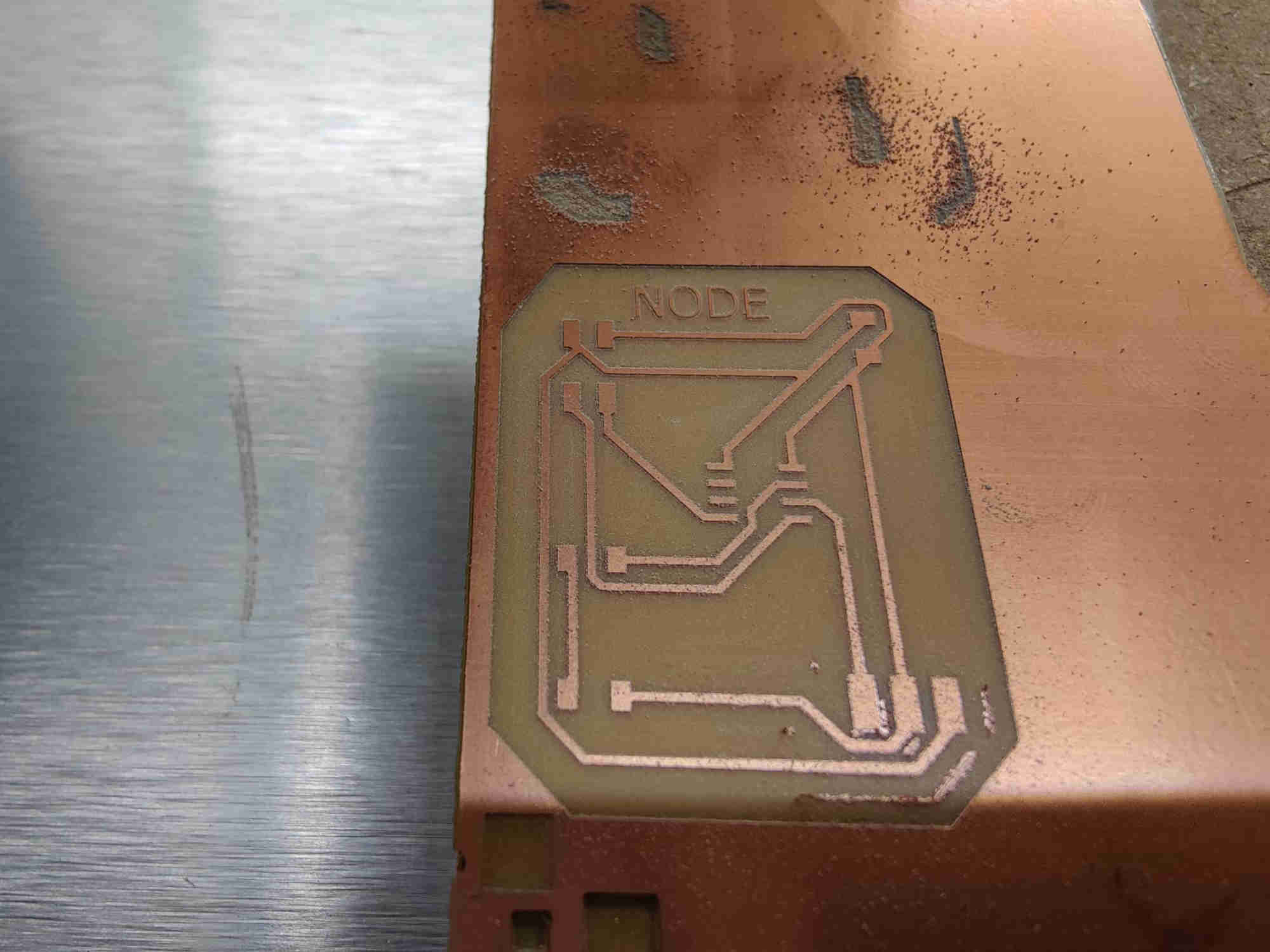
Node
Bridge
Electronics components what is necessary:
For work with ATTINY 412 is needed:
-
Attiny 412 chip
-
One unpolarized capacitor, 1uF
-
2x FTDI connector
-
Build in the UPDI connector 4.99 K resistor
For Power LED is needed:
-
LED
-
One Resistor, 1K
For communication Media - Vertical Pinheader pitch 2.54 mm, D=1.4 mm ( 2x2)

Chip
-
PIN1 >VCC
-
PIN2>FTDI TXD
-
PIN3> FTDI RXD
-
PIN6>4.99kΩ resistor> UPDI TXD
-
PIN7>1 kΩ resistor>LED>GND
-
PIN8> GND
CONN 2x2 Pinheader
-
PIN1>VCC
-
PIN2>ATTiny 412 PIN 2
-
PIN3>GND
-
PIN4> ATTiny 412 PIN 4
FTDI
-
PIN1>GND
-
PIN3>VCC
UPDI
-
PIN1>GND
-
PIN3>VCC
-
PIN5> ATTiny 412 PIN 6( between resistor and chip PIN 6)
Capacitor
-
GND
-
VCC

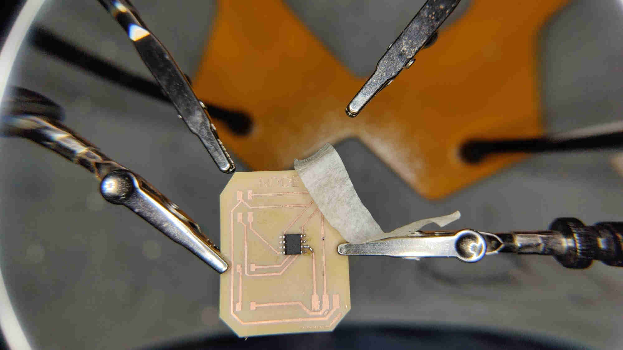
Node
For work with ATTINY 412 is needed:
-
Attiny 412 chip
-
One unpolarized capacitor, 1uF
-
UPDI connector
For Power LED is needed:
-
LED
-
One Resistor, 1K

b>Chip
-
PIN1 >VCC
-
PIN4> CONN 2x2 Pinheader PIN 2
-
PIN5> CONN 2x2 Pinheader PIN 4
-
PIN6>UPDI PIN1
-
PIN7>1 kΩ resistor>LED>GND
-
PIN8> GND
CONN 2x2 Pinheader
-
PIN1>VCC
-
PIN3>GND
UPDI
-
PIN2>GND
-
PIN3>VCC
Capacitor
-
GND
-
VCC

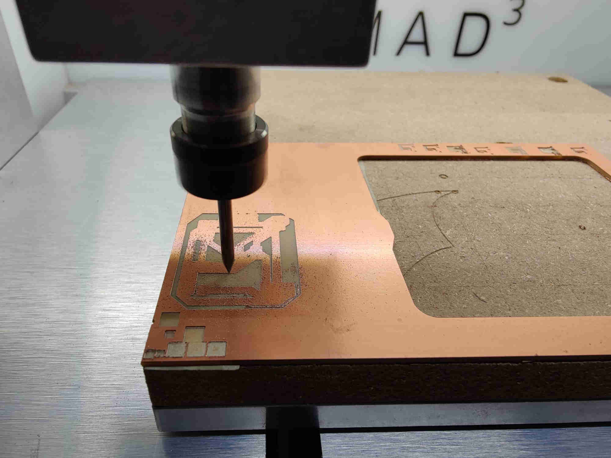
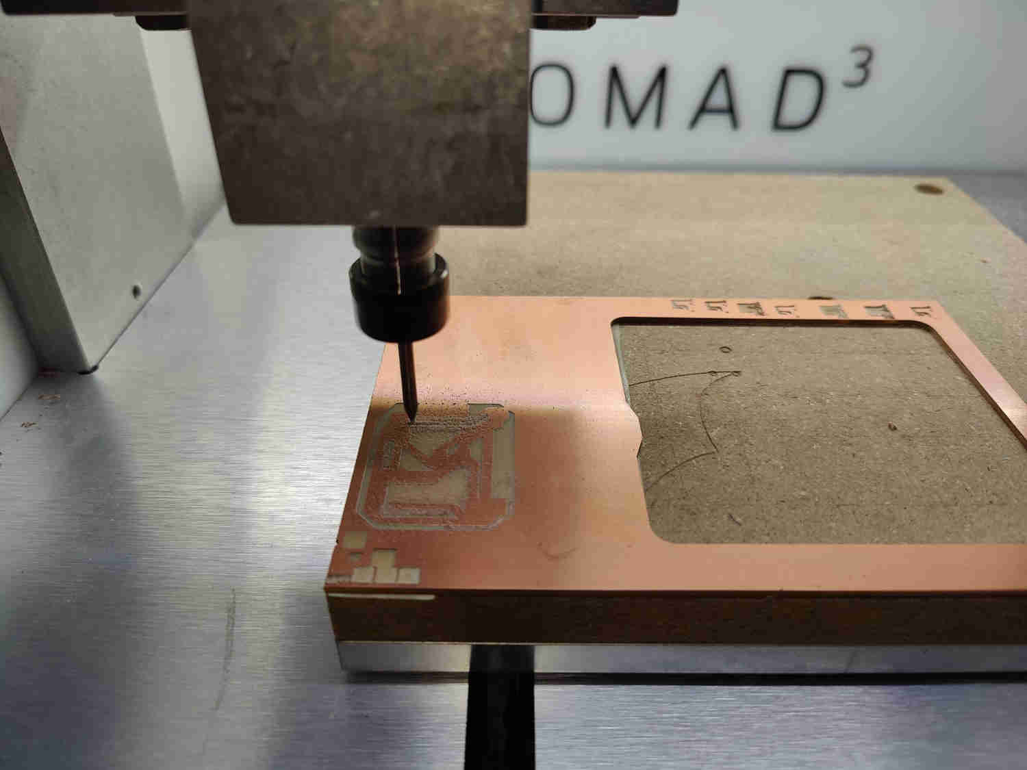
Build process

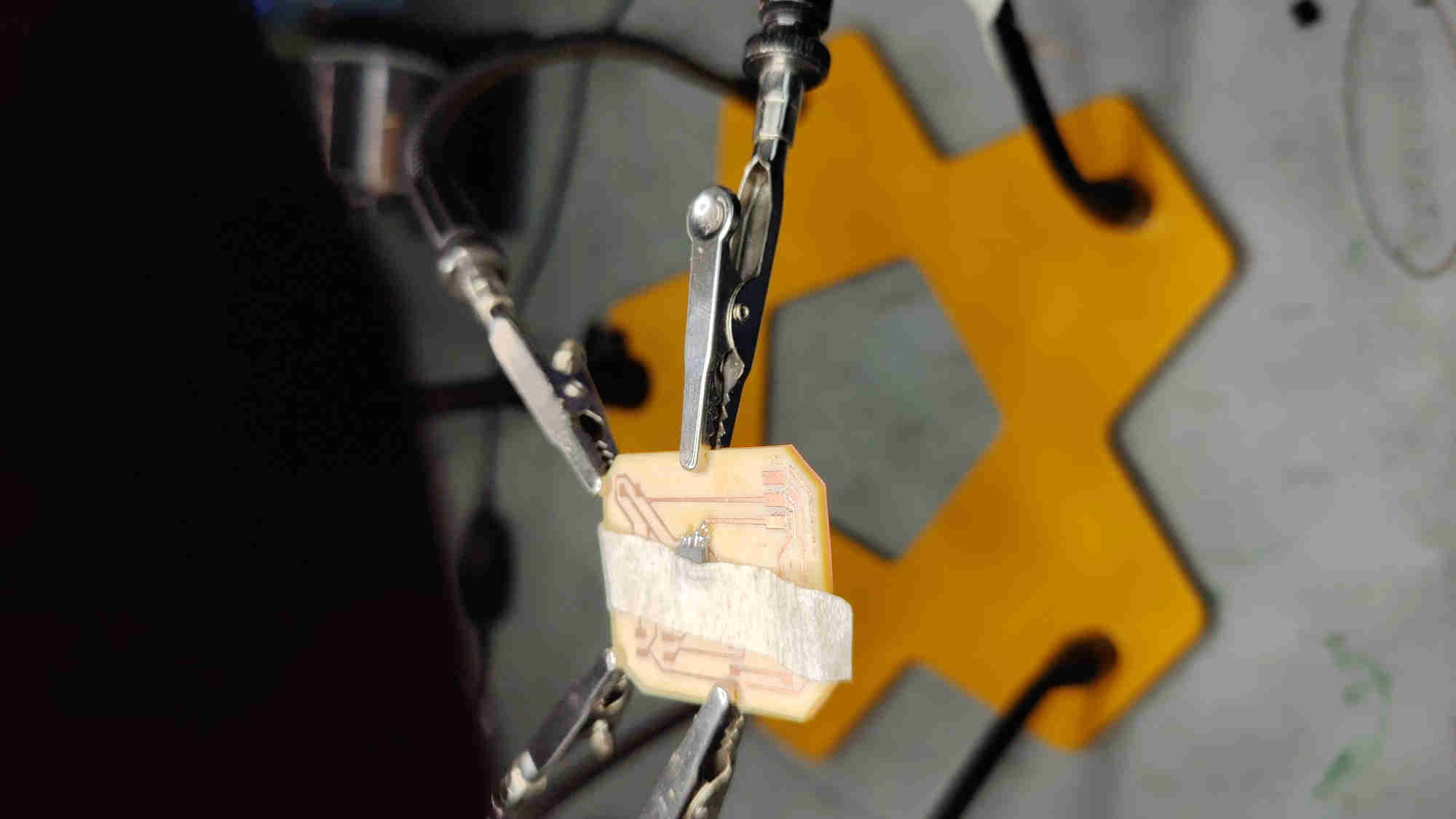

Programming
Bridge Code
I used Adrian’s Torres code and made a minor change to the RX and TX serial number code. Which i changed from 2,3 to 0,1 due to changes I made in the electronic design schematic .
#include <SoftwareSerial.h>
SoftwareSerial mySerial(0,1); //RX, TX
int v=0;
int nodeid=1; //Node Identification
int i=0;

void setup() {
  mySerial.begin(115200); //initialize serial communications
  pinMode(4, OUTPUT); // led
}

void loop() {
  for (i=1;i<=3;i++){ // initialization; condition; increment
  mySerial.println(i); // print value to Serial
  delay(1000);
  }

  while (mySerial.available () == 0 ) {}  //while serial is 0
  v = mySerial.parseInt();
  if(v == nodeid)        //If the value of v equals the identification of the node
{
  digitalWrite(4,HIGH);
  delay(200);
  digitalWrite(4,LOW);
  delay(200);
}
else
{
  digitalWrite(4,LOW);
 }
}
Node Code
I used Adrian’s Torres node code.
#include <SoftwareSerial.h>
SoftwareSerial mySerial(2,3); //RX, TX
int v=0;
int nodeid=2;//Node Identification

void setup() {
  mySerial.begin(115200); //initialize serial communications
  pinMode(4, OUTPUT); // led
}

void loop() {
  while (mySerial.available () == 0 ) {} //while serial is 0
  v = mySerial.parseInt();
  mySerial.println(v);
  if(v == nodeid)     //If the value of v equals the identification of the node
{
  digitalWrite(4,HIGH);
  delay(200);
  digitalWrite(4,LOW);
  delay(200);
}
else
{
  digitalWrite(4,LOW);
 }
}
Download Files
Success !