10. Molding and casting
Molding is the act of creating the cavity / form that carries a negative or reverse impression of an original model. Molds can be made of a rigid material, such as plaster or plastic resin or more commonly, a flexible material such as rubber. The material to use should be chosen considering the material of the model, the material to be used to make castings, and whether there are any undercuts. Casting is the act of pouring liquid material into the cavity of a mold. After a period of time, this liquid will cure via chemical reaction or cooling. The solidified part is also known as a casting, which is ejected or broken out of the mold to complete the process. Casting materials are usually metals or various cold setting materials that cure after mixing two or more components together; examples are epoxy, concrete, plaster and clay.
Learning outcomes:
-
Design appropriate objects within the limitations of 3 axis machining
-
Demonstrate workflows used in mould design, construction and casting
Like the previous weeks , student are expected to complete two (2) categories of weekly assignment.
-
Group assignment:
-
Review the safety data sheets for each of your molding and casting materials
-
Make and compare test casts with each of them
-
-
Individual assignment:
- Design a 3D mould around the stock and tooling that you’ll be using, mill it (rough cut + (at least) three-axis finish cut), and use it to cast parts.
Group Assignment
For our Group assignment we had to review the safety data sheet for each of your molding & casting materials and Make and compare test casts with each of them
The Group Assignment page is as follows Link
Group Members:
-
Nervene Bhagwandass
-
Christopher Proute
-
Terrence Carew
-
James Khan
-
Marvin Holloway
-
Ravi Baldeo
Individual Assignment
My Individual assignment decided to make a small 3D model of Darth Vader head similar to the design used in the Computer controlled cutting assignment . As I had an image I iimport it in to inkscape and trace the bitmap export it as a DXF file. I then open the file in Fusion 360 and made the necessary edits base on the tool I will be using (#122 End Mill 1/32”).
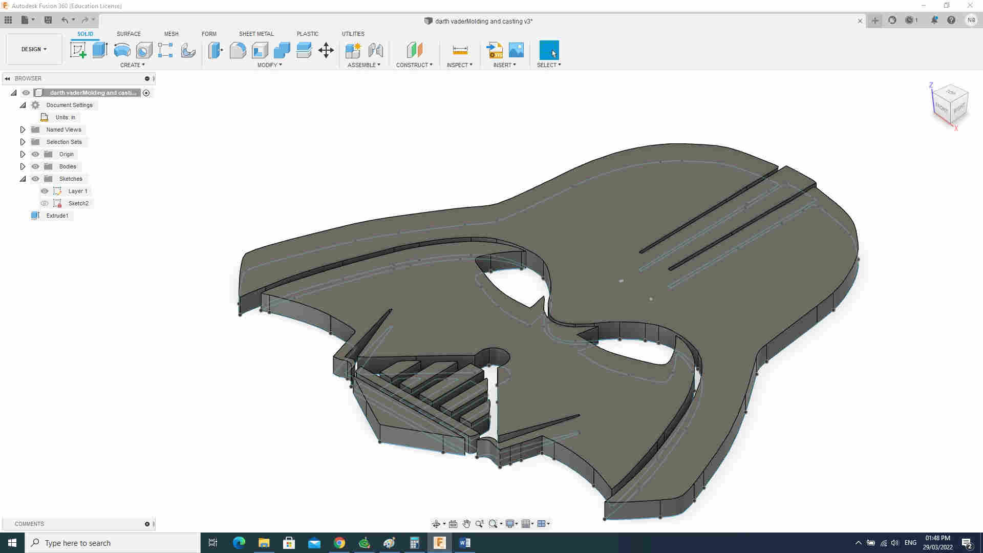
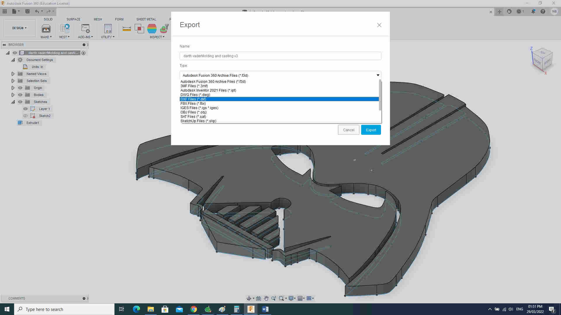
After editing I exported to dxf file.
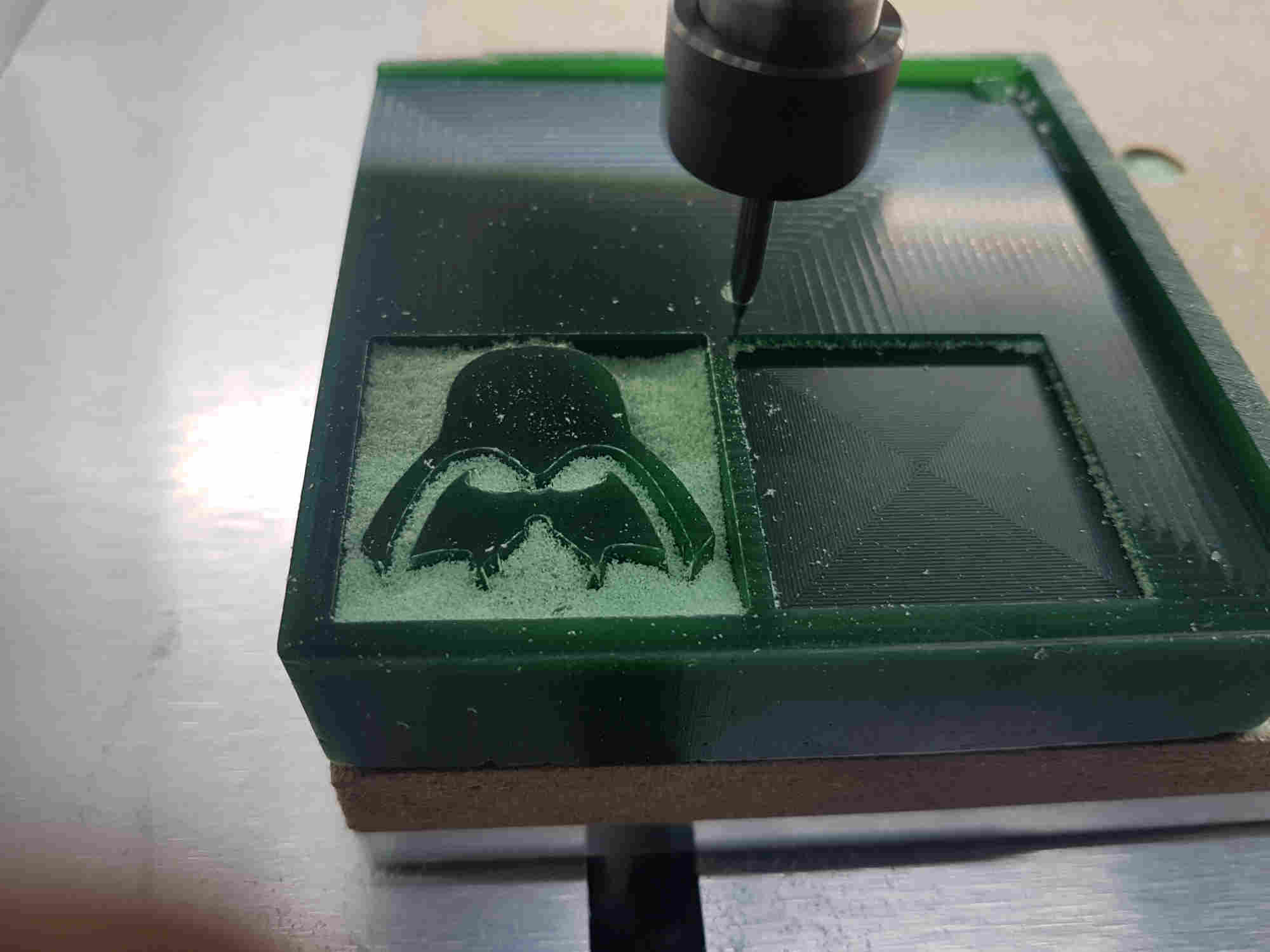
Milling in Carbide Create
Toolpaths in Carbide Create
I use three Pocketing Toolpaths for this process.
My first cut was Pocketing Toolpath 6 had a start depth of 0.00 and a max depth 0.08 inches.

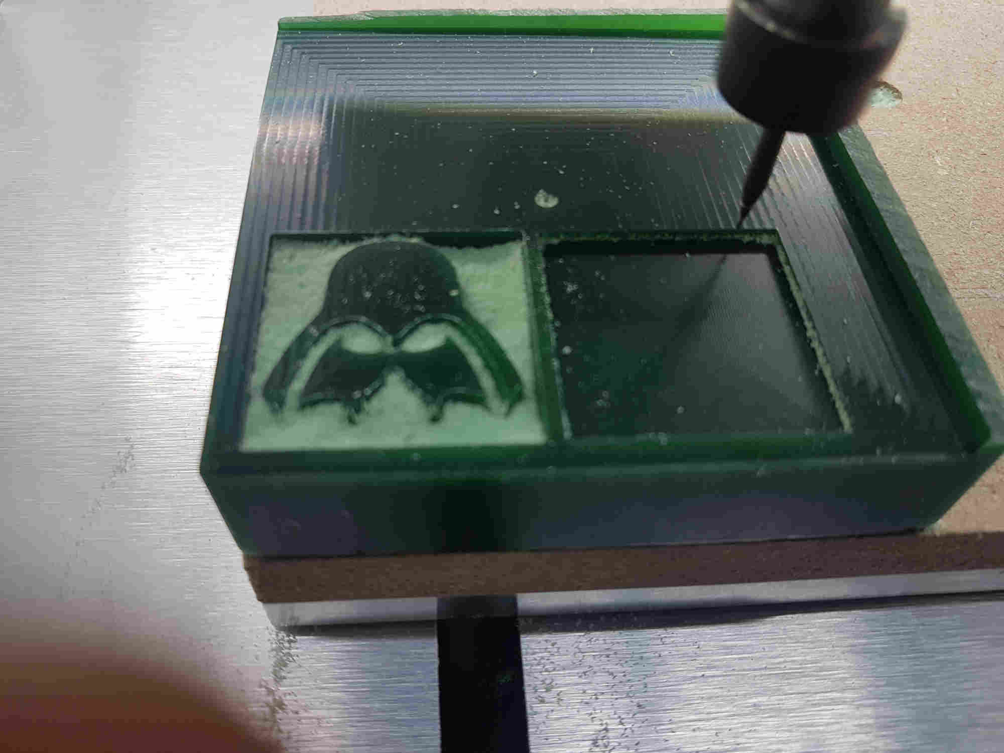
My second cut was Pocketing Toolpath 4 had a start depth of 0.08 and a max depth 0.16 inches.
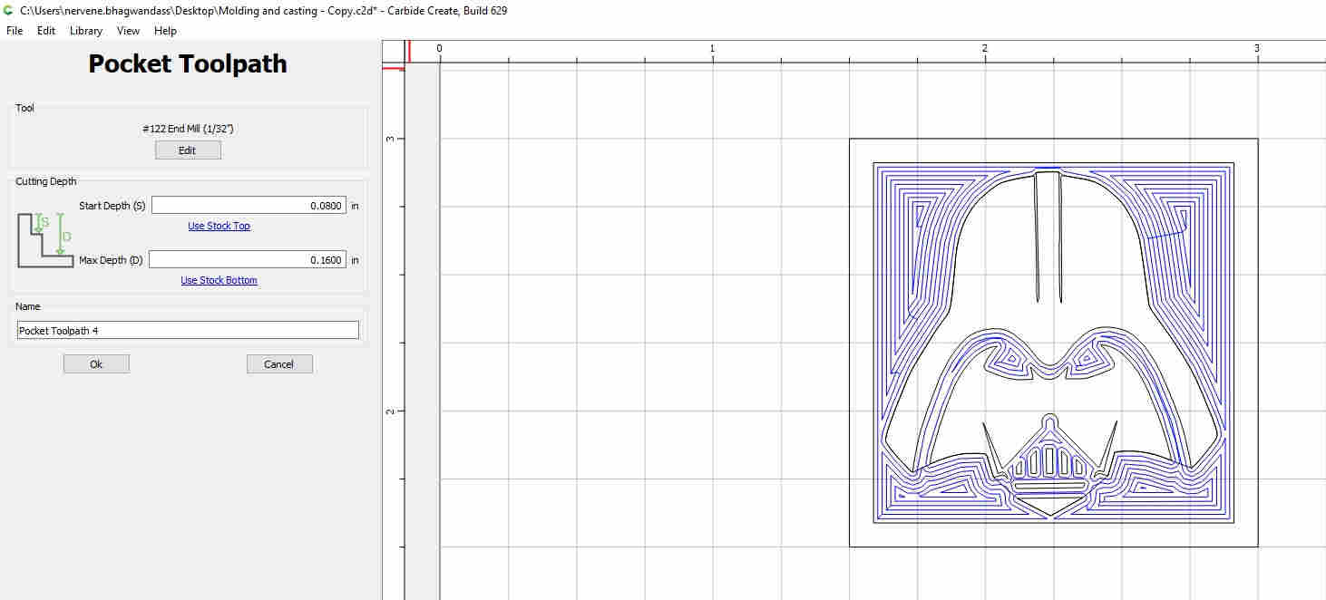
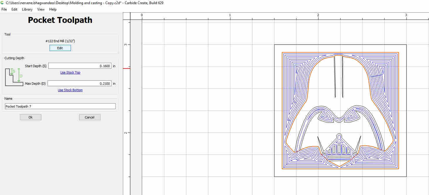
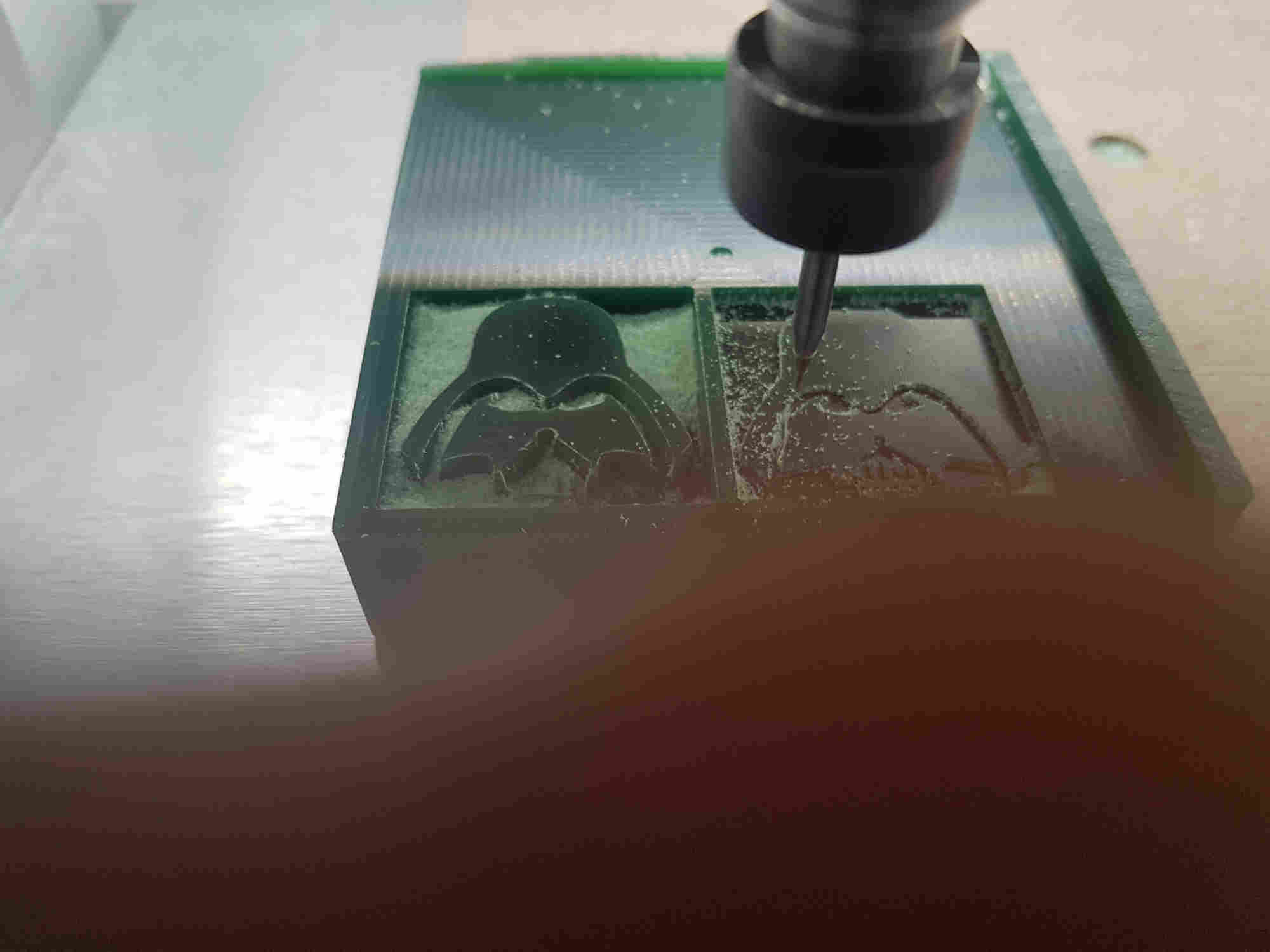
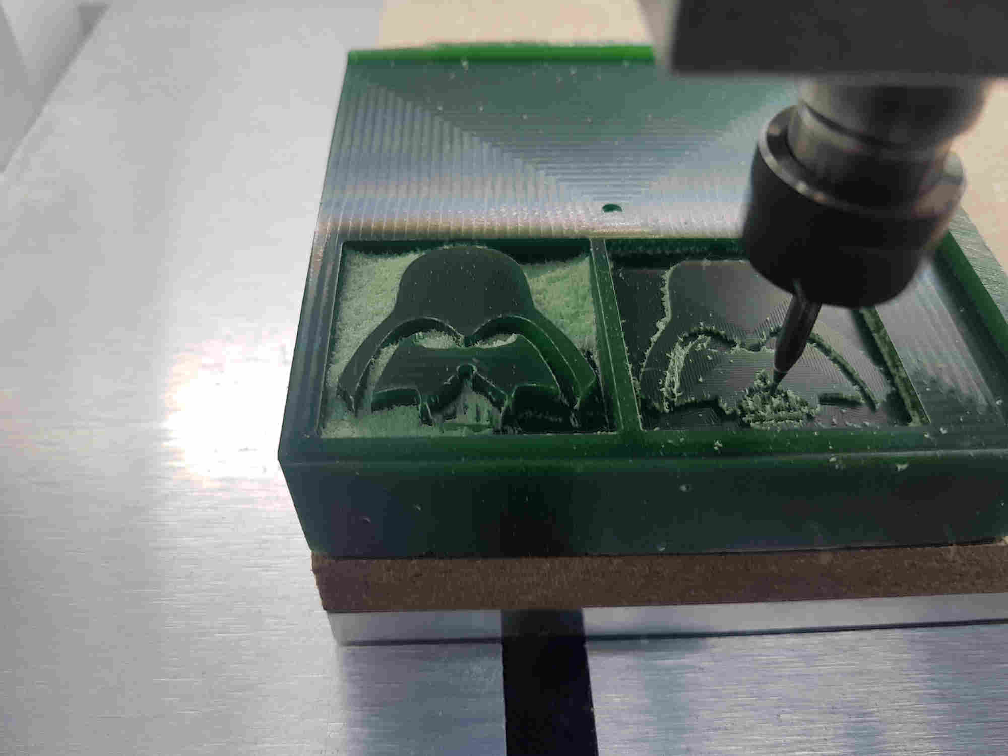
My final cut was Pocketing Toolpath 7 had a start depth of 0.16 and a max depth 0.21 inches.
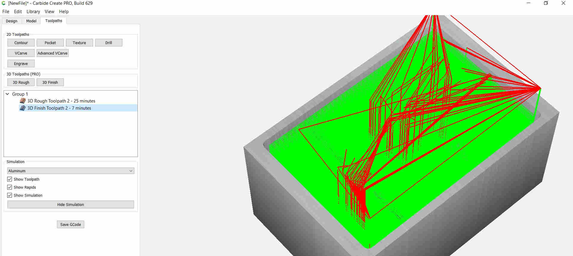
Toolpaths with estimated times.
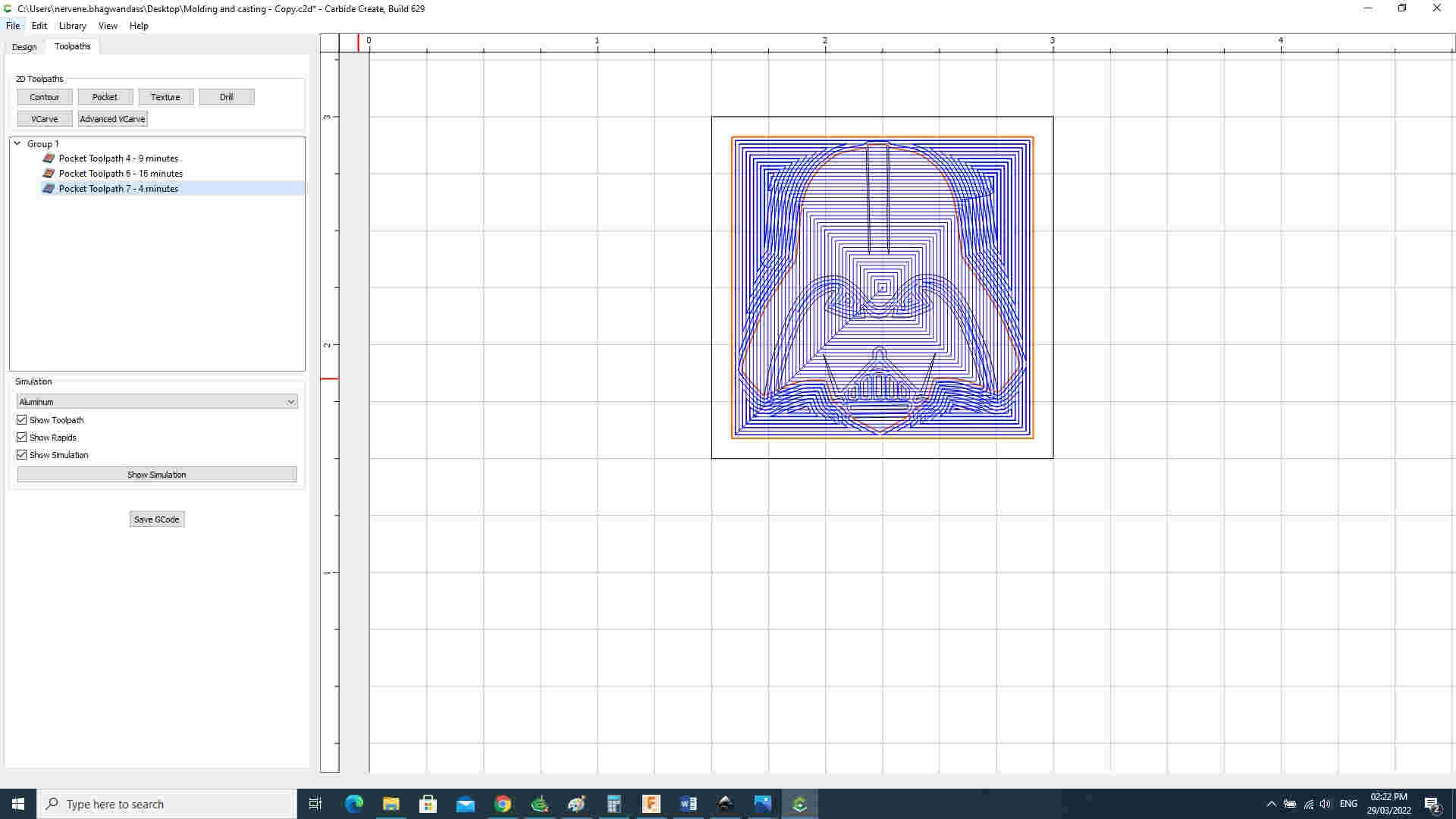
All tool parts were save as g code
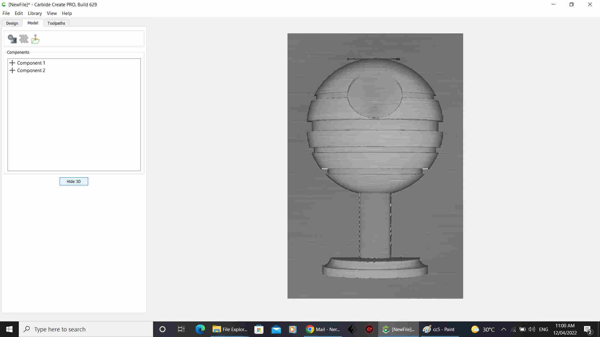
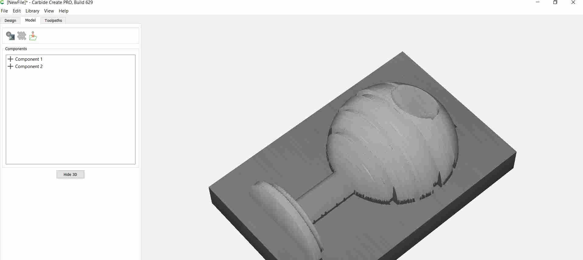
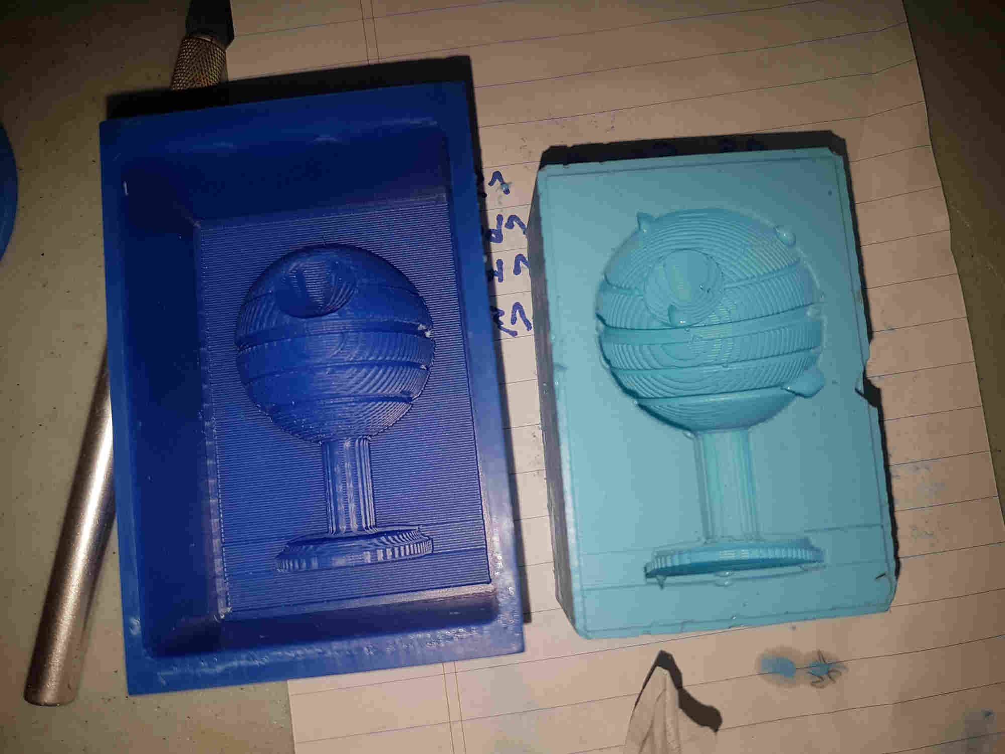
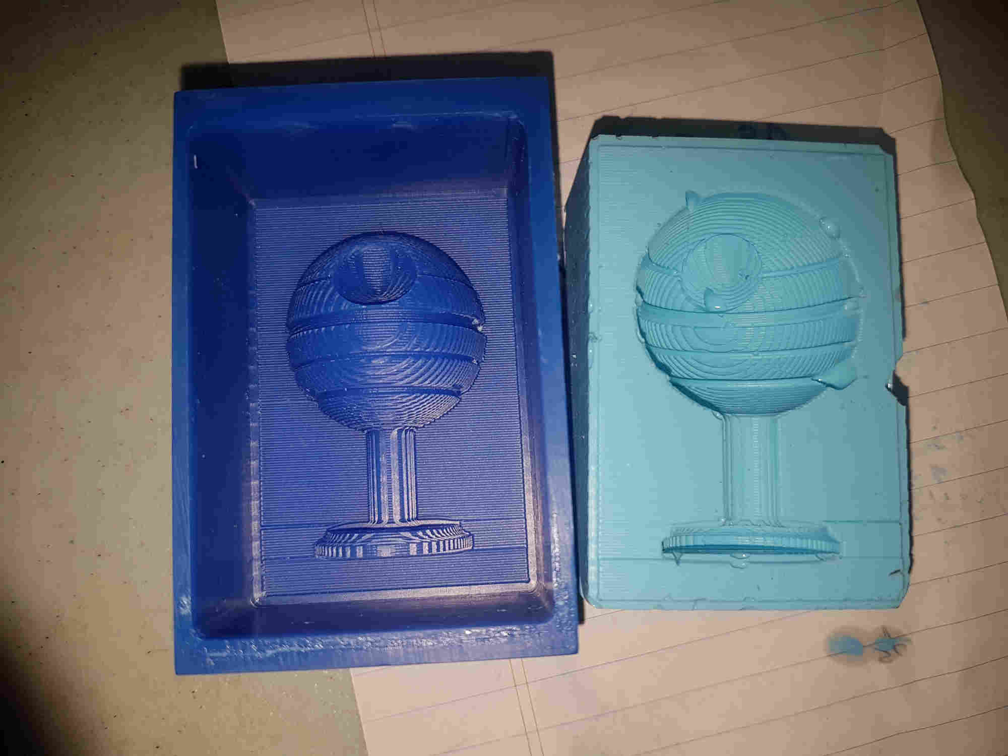
After consulting with Jason I realize that my milling was not utilizing three axis of the machine so I redesign a 3D model of the Death Star in Fusion export it as stl file
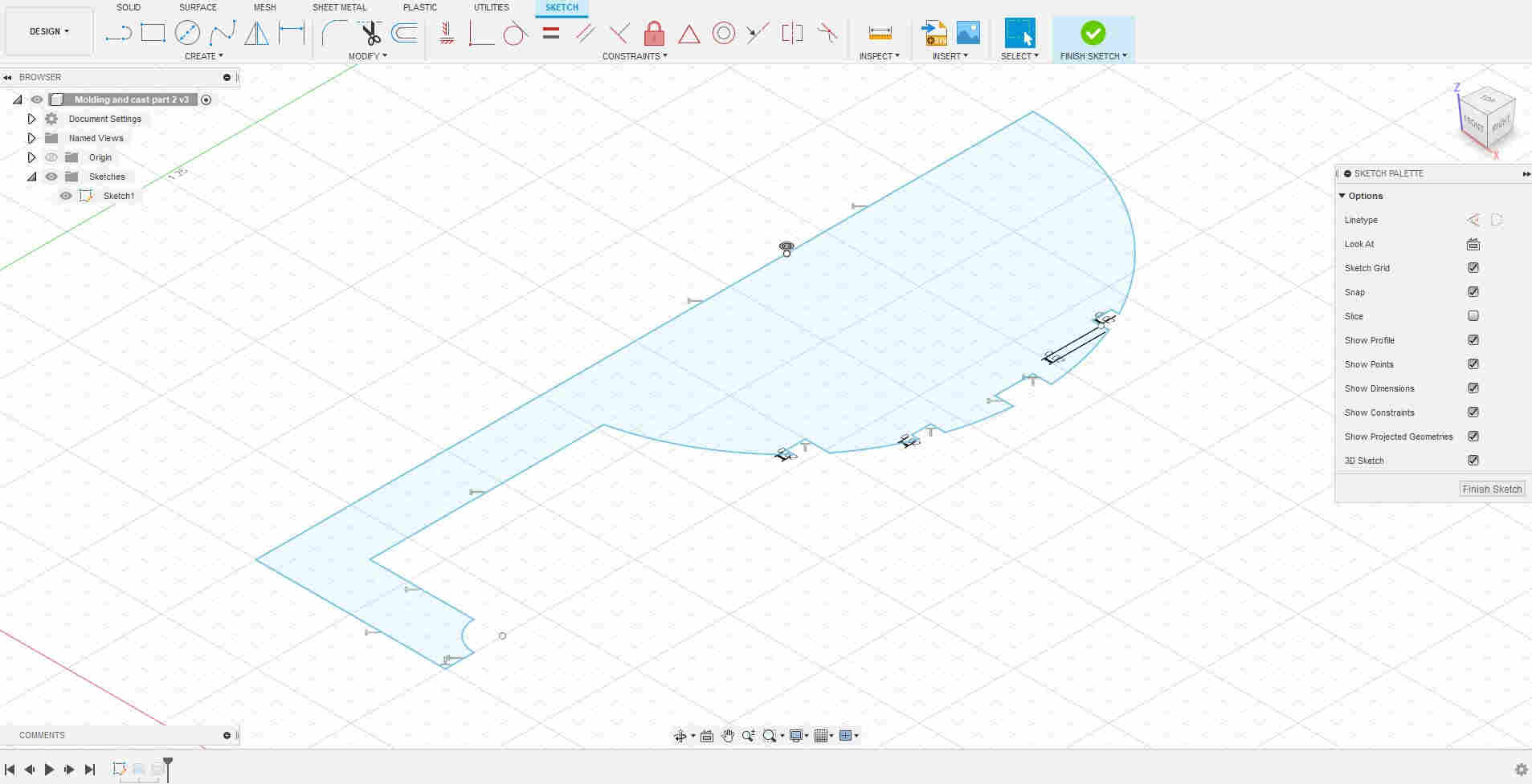

f3d Desgin file download deathstar
Note: before I move to next step I had to record the
-
Width : 1.296 inches
-
Height: 2.051 inches
-
Depth: 0.648 inches
Then I converted the stl to heightmap image using online STL to PNG conversion tool and input the dimensions
- I made sure and set units to imperial as drawing was in inches And choose your stl file


I then download image filename.stl.png
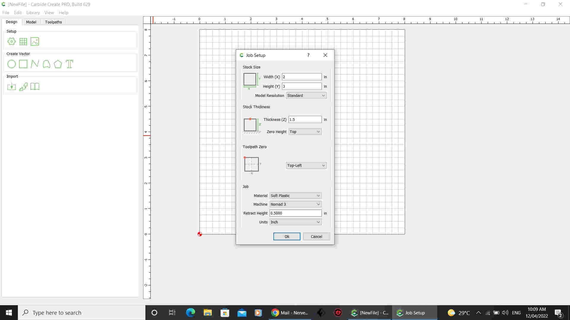
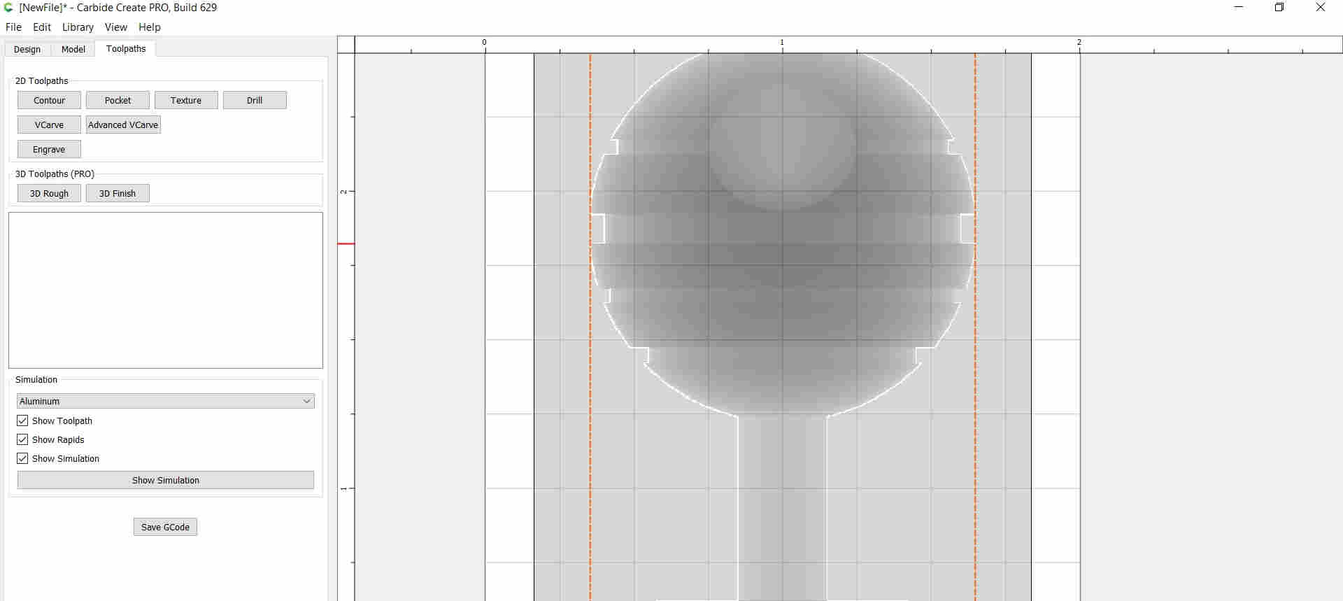
I then setup the job and input your material stock size, and the material thickness and choose “Top” for Zero Height
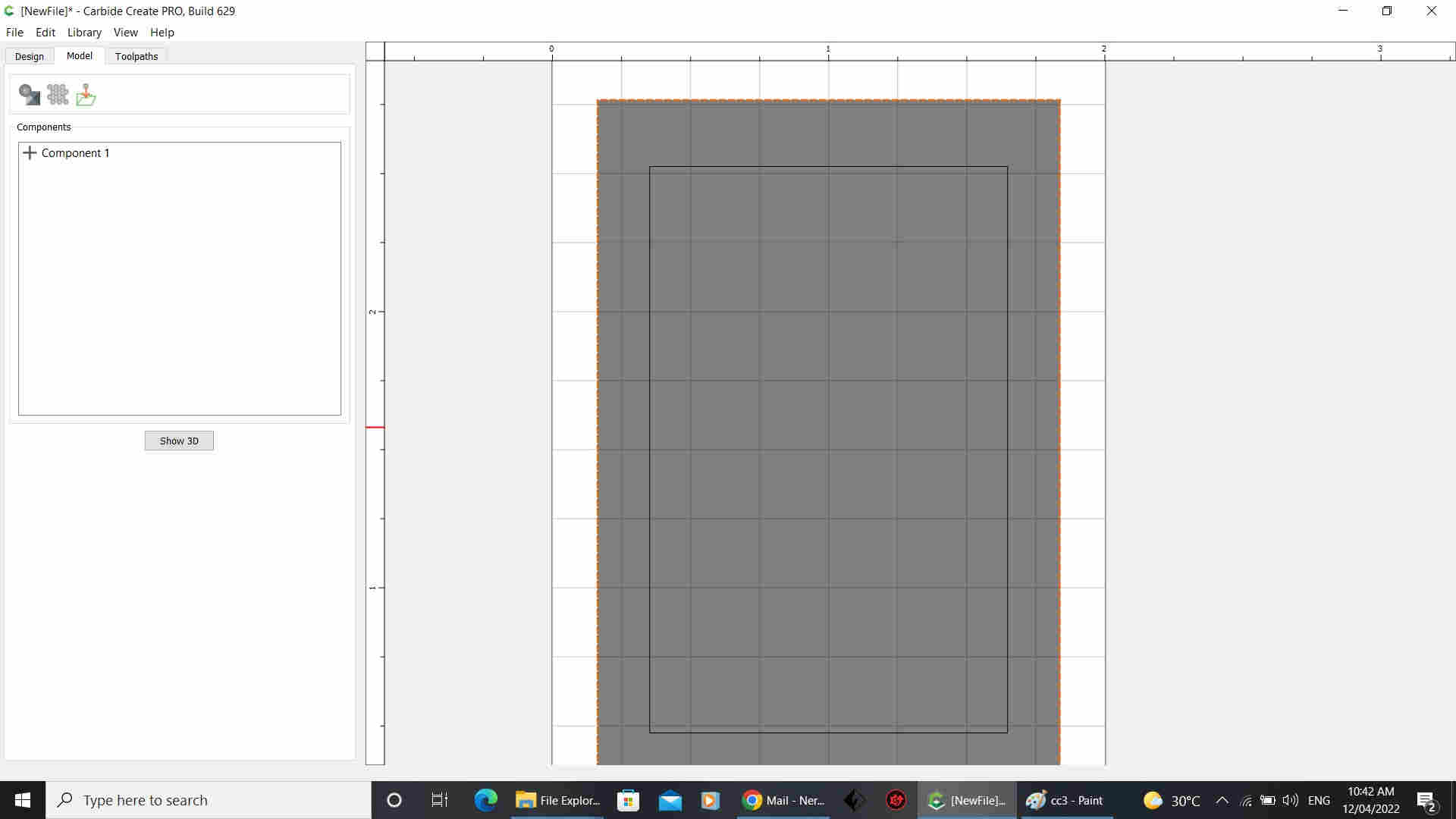
I then created two rectangles
-
One with the size of the stl part, same as the “Stock width and height” I input into the web tool
-
Second one with the size of the “box” want to create for the positive mold

I selected the outer square which I need to create one shape to set the milling depth for my part under the Model tab >add shape
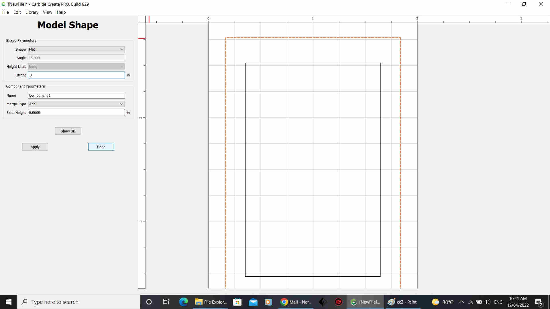
I set the shape to flat and set the height to the thickness of the material I want to keep below the part
In the model tab, I select the inner square (the one that has the same size as our part). With the inner square selected, click “Import Image”
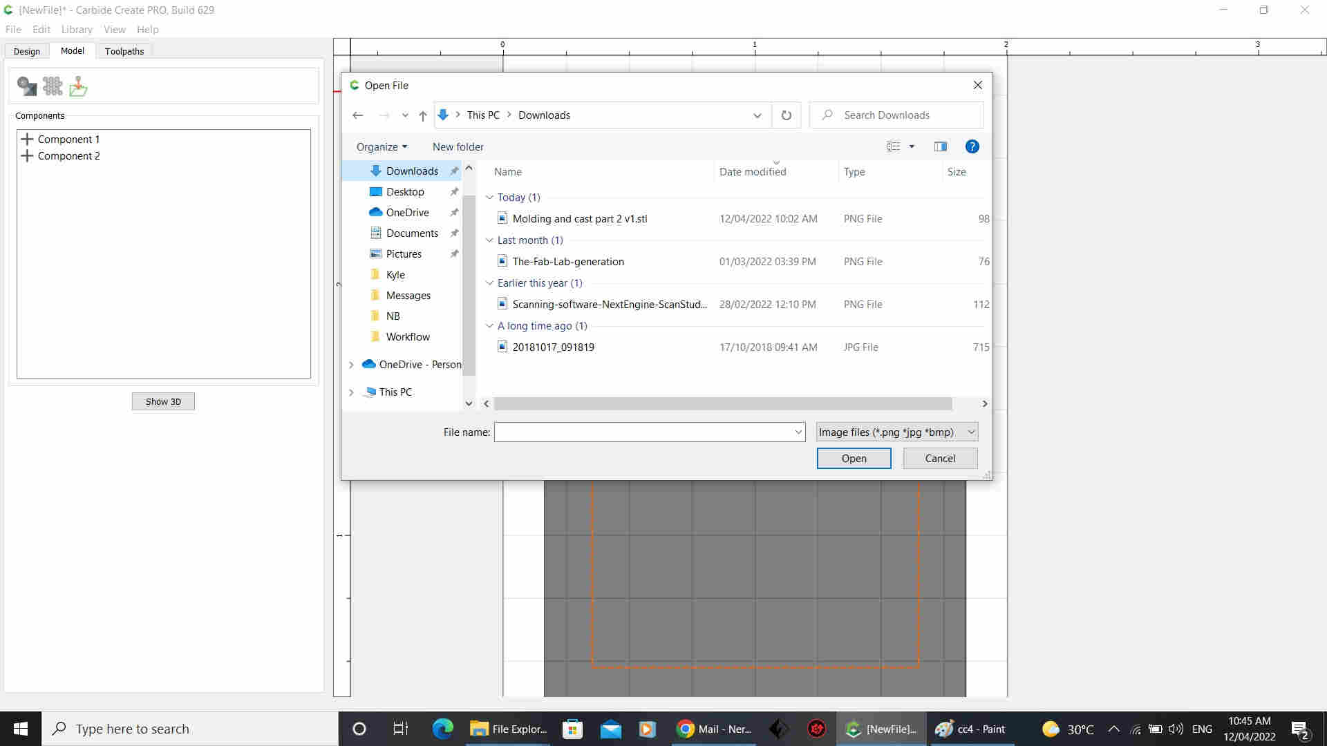
Model Import” window, set the “Height” to the thickness of the part
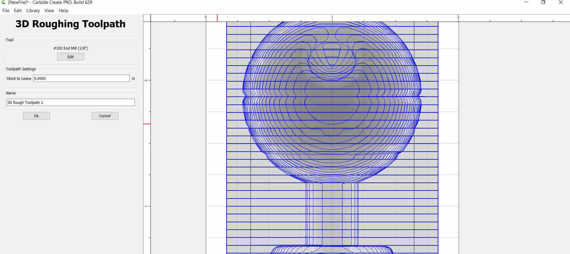
I then created a roughing toolpath using #102 End Mill(1/8”)
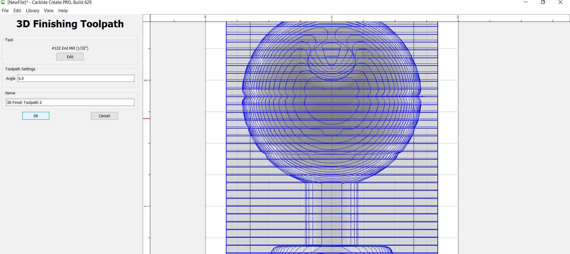
I then created a finishing toolpath using #122 End Mill (1/32”)
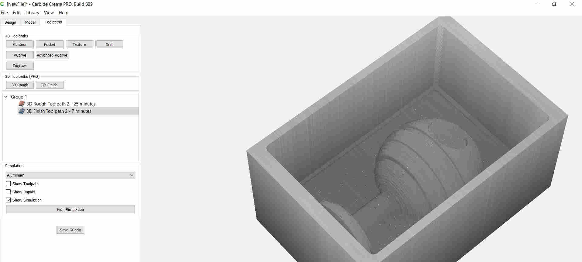
Estimated milling time and there simulation

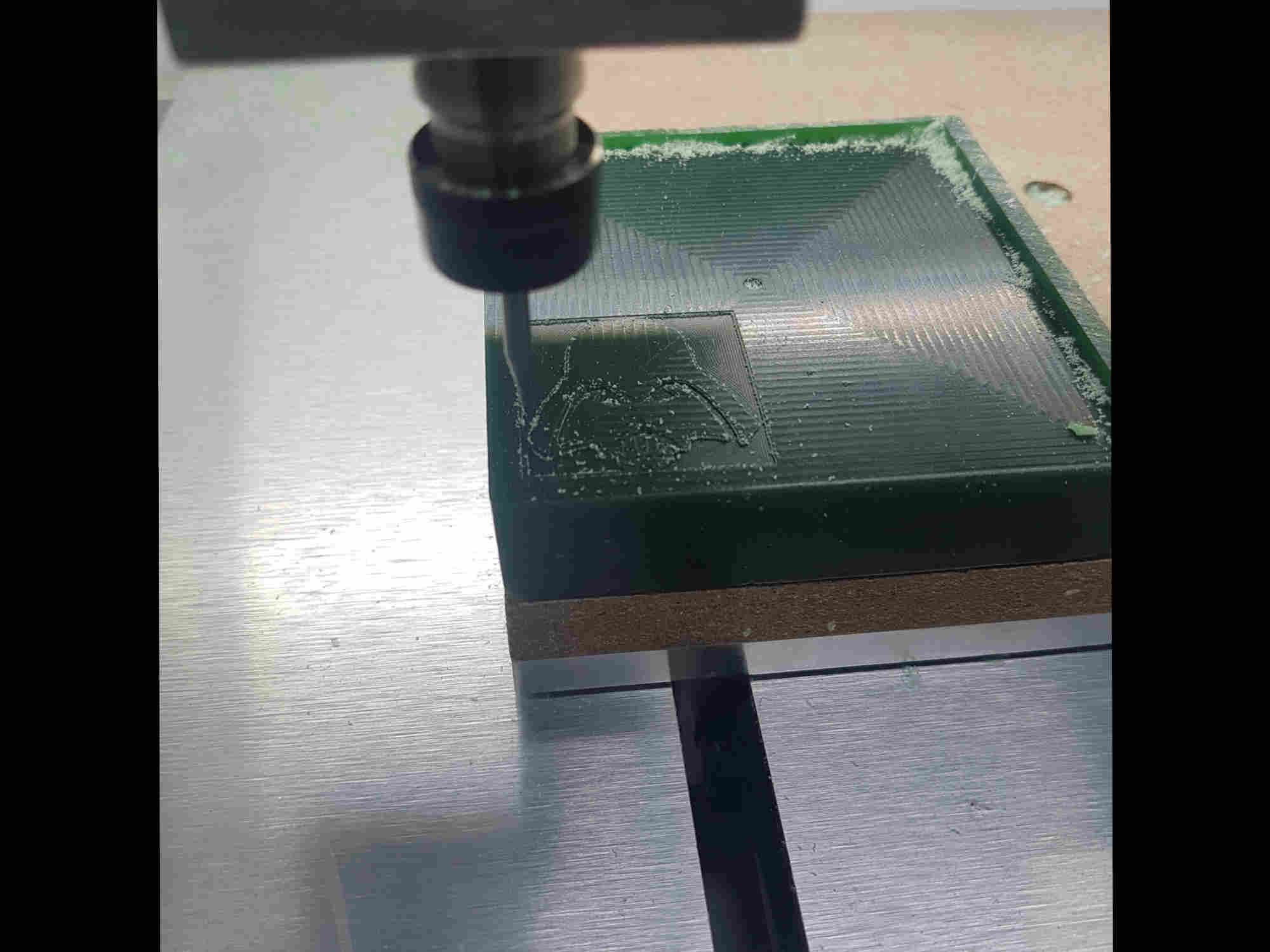
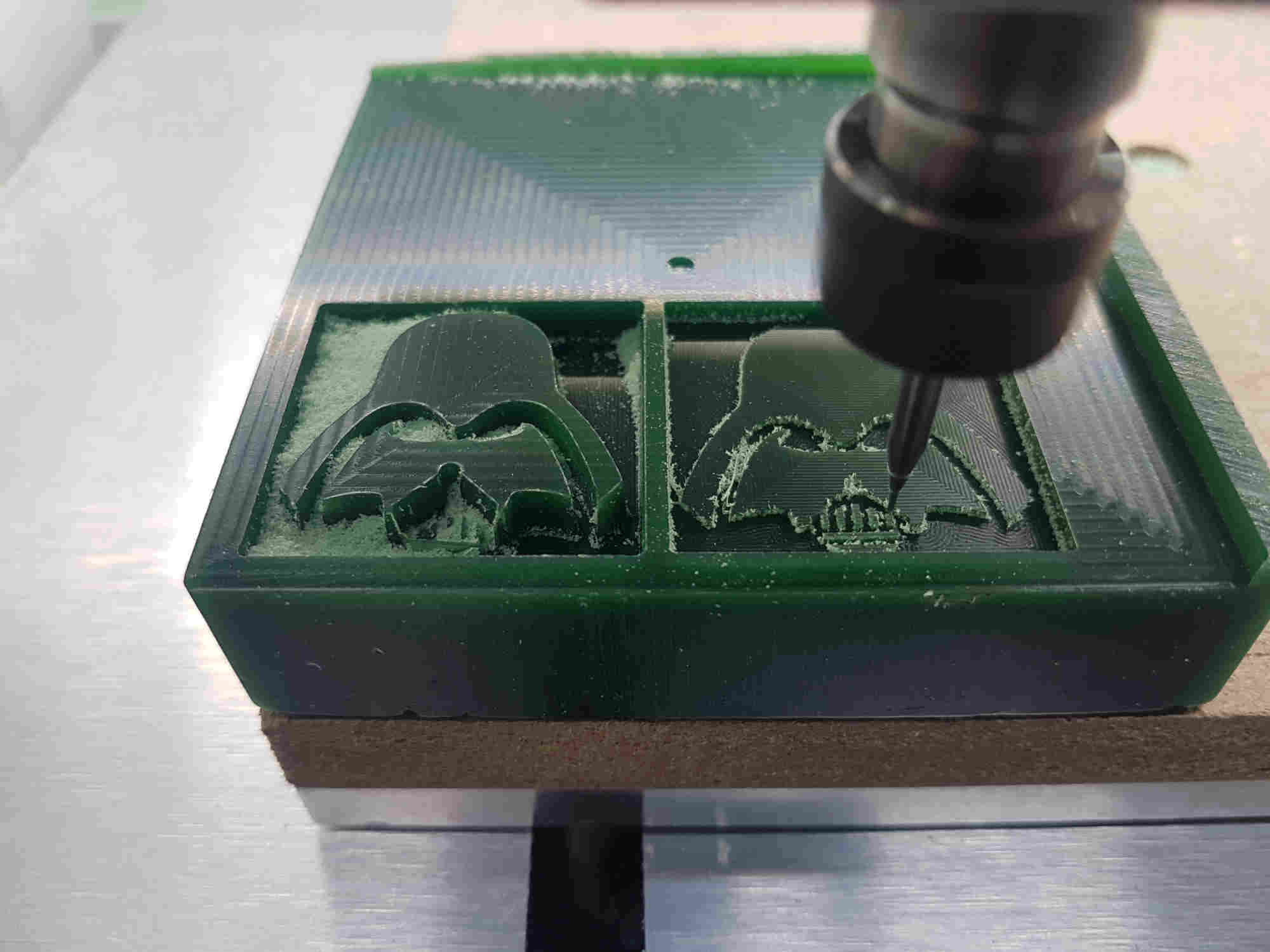
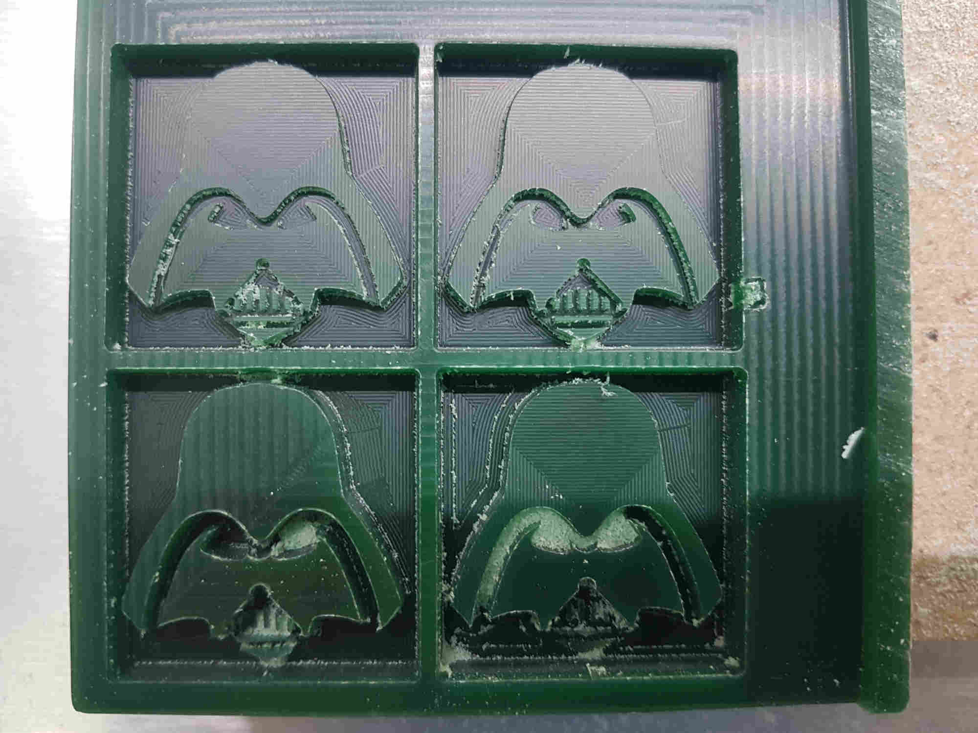
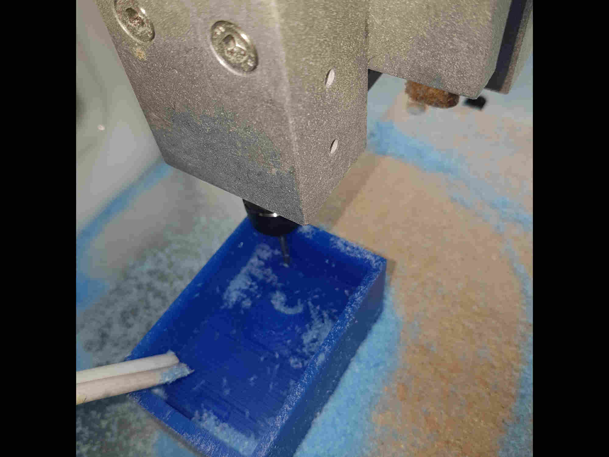
First Milling Process on the Nomad3
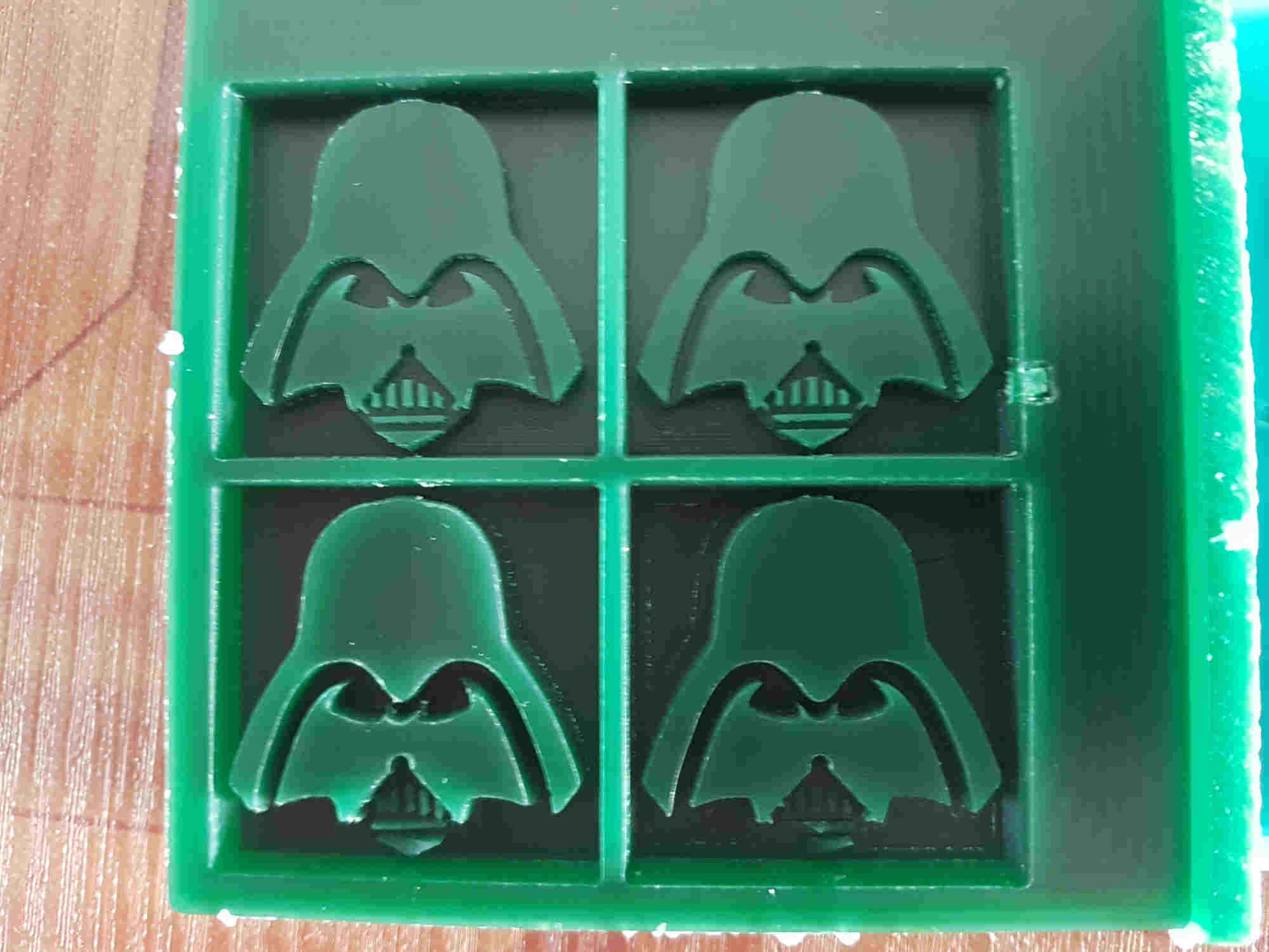
I used a piece of molding wax 3.5”x 3.5” x 1” and because I used a table saw to cut it from the original block it had and uneven top surface so I had to mill it level and then begin the milling
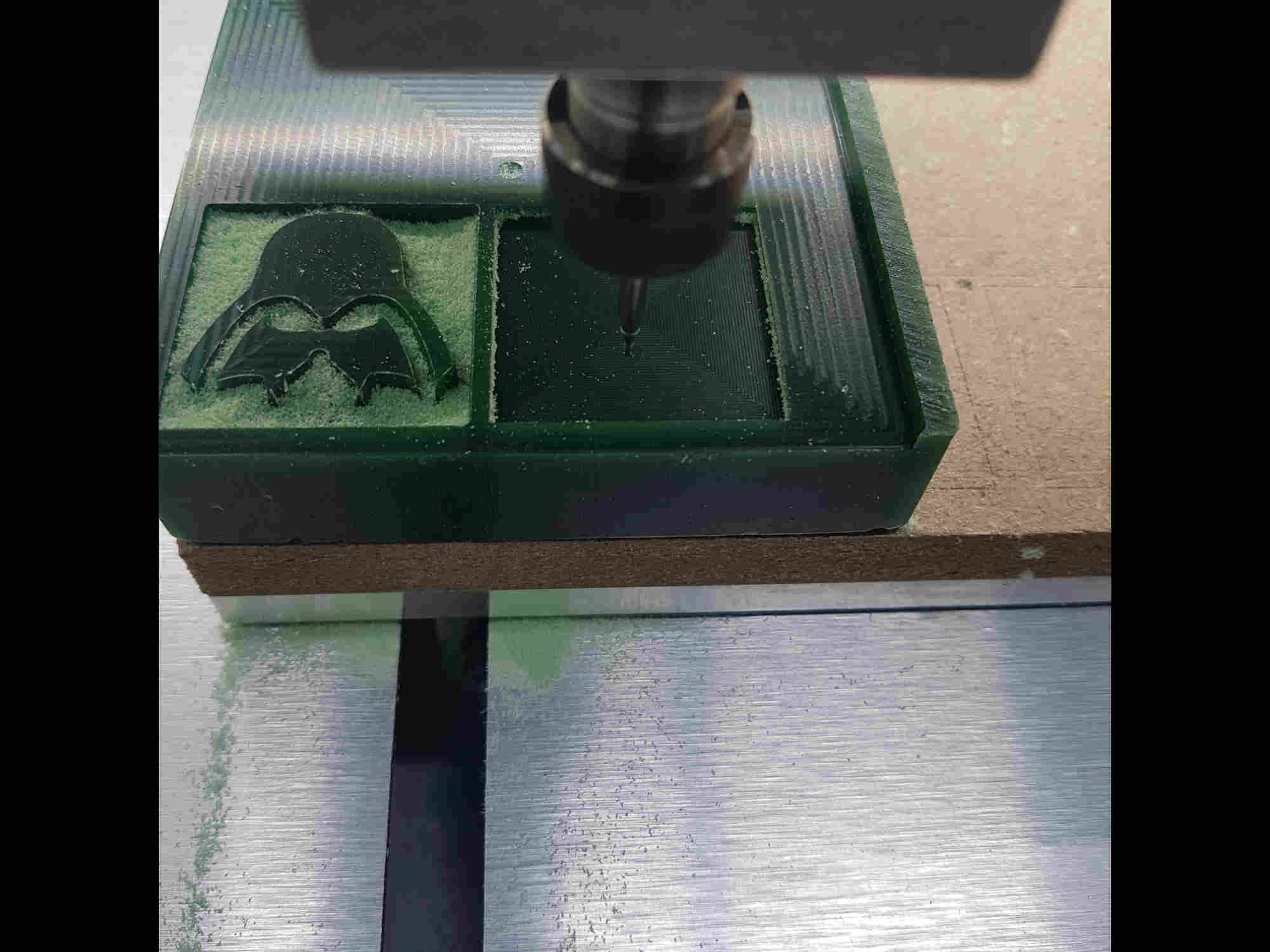
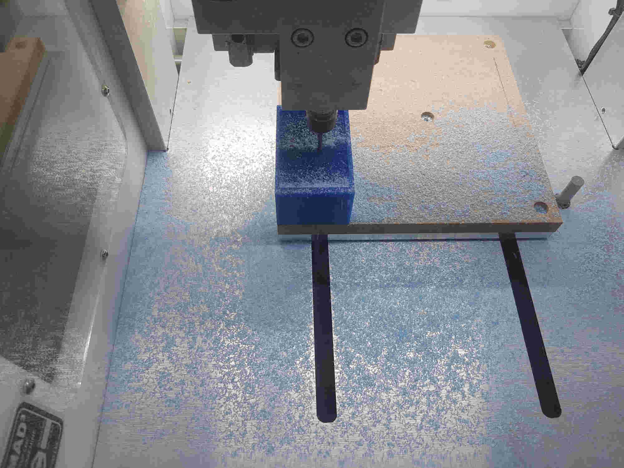
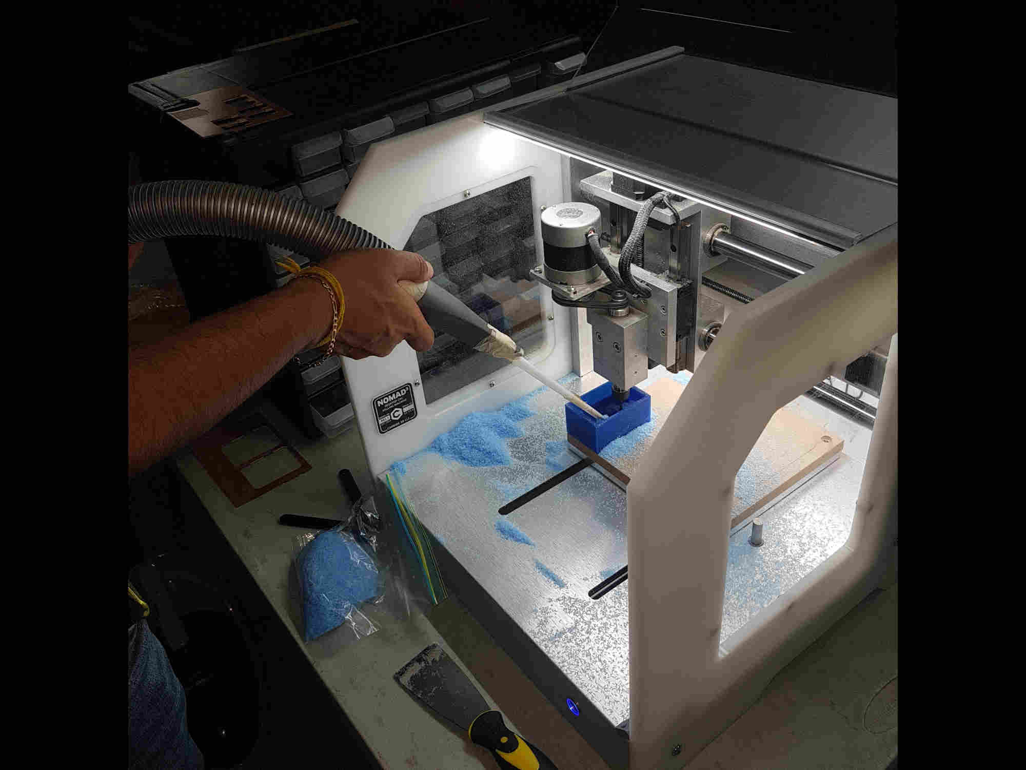
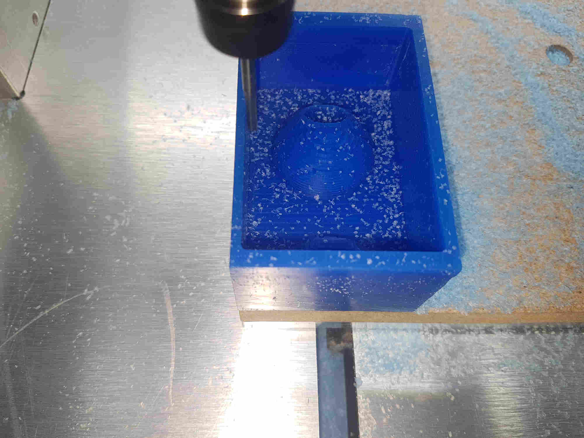
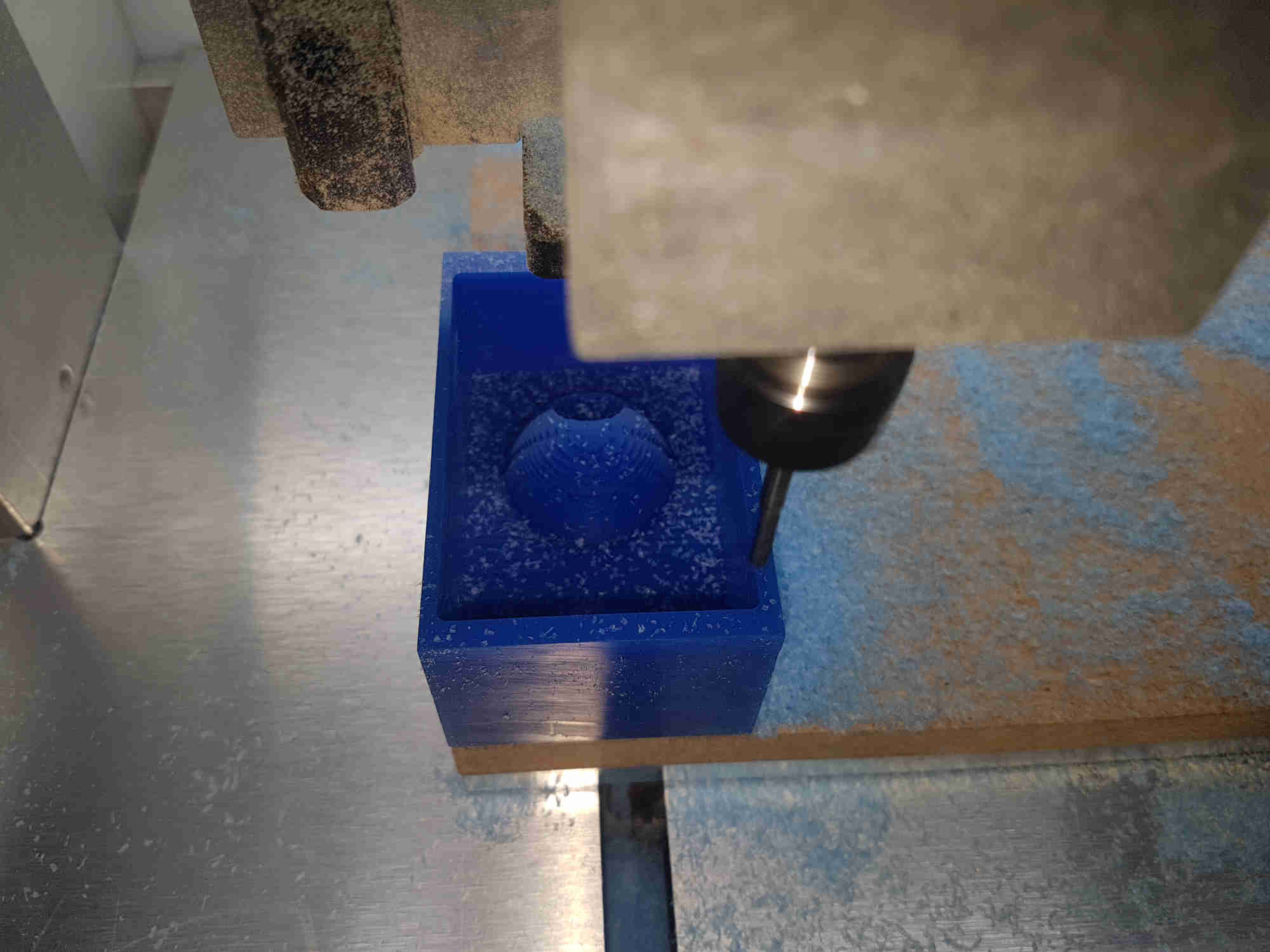
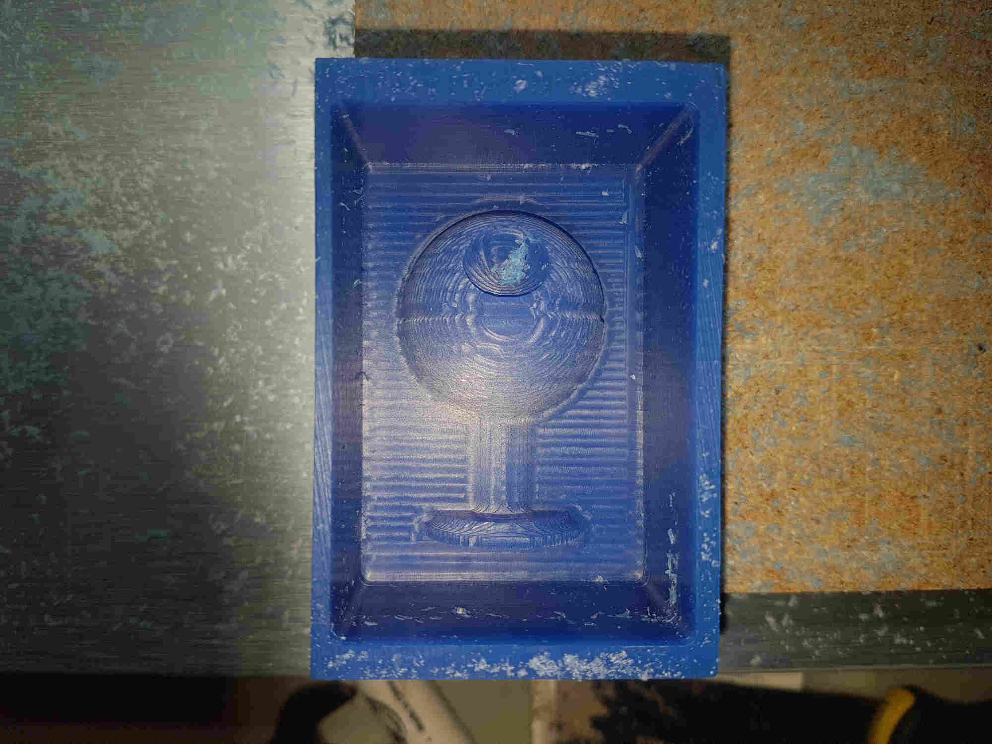
Second Milling process
I used a piece of molding wax 2”x 3” x 1.5” and begin the milling
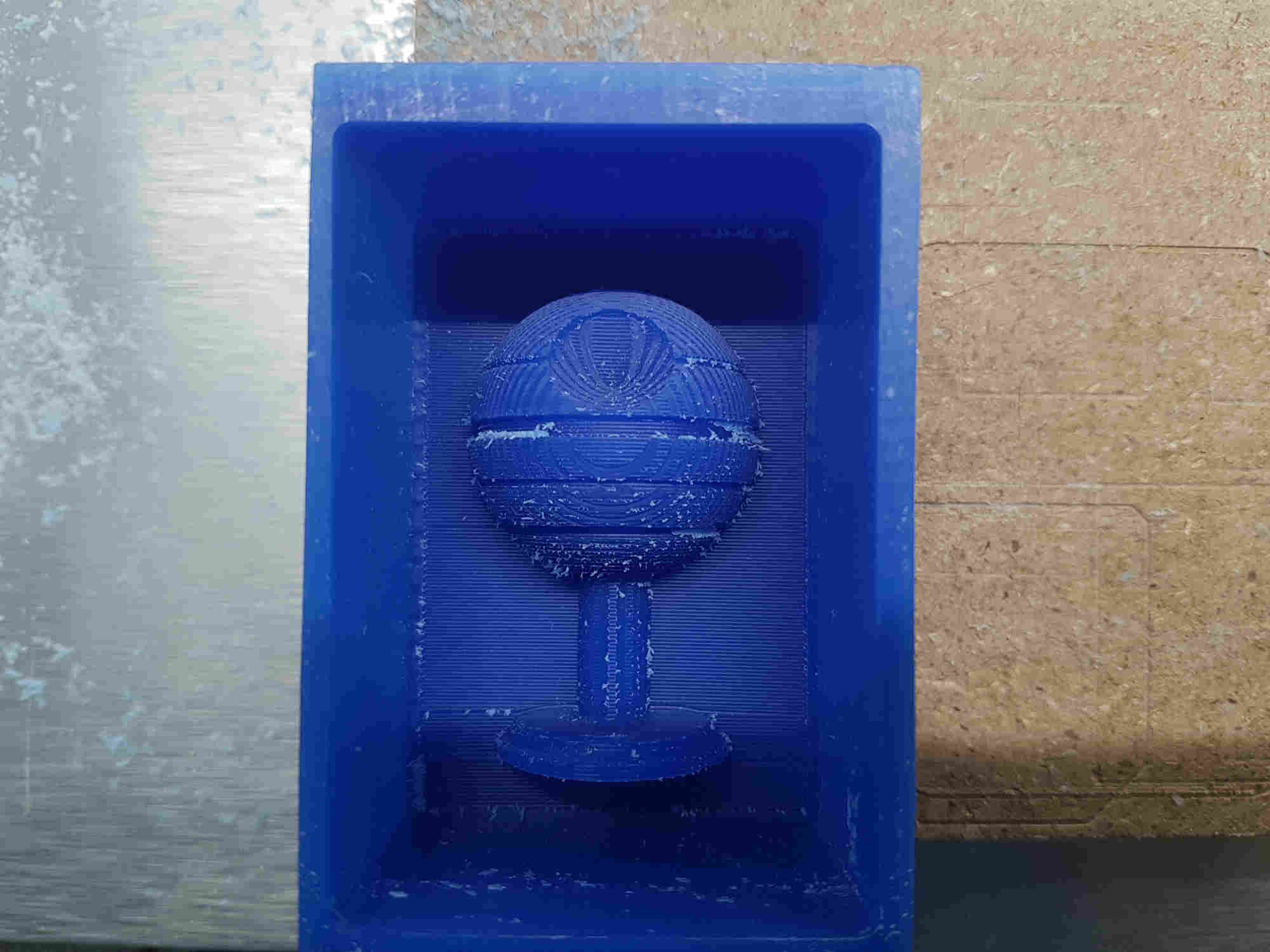
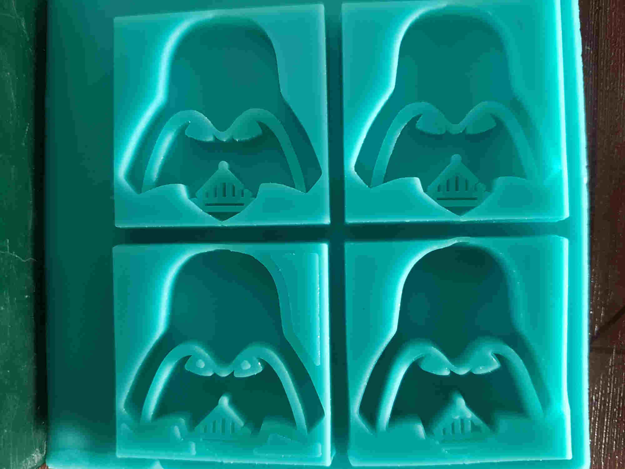
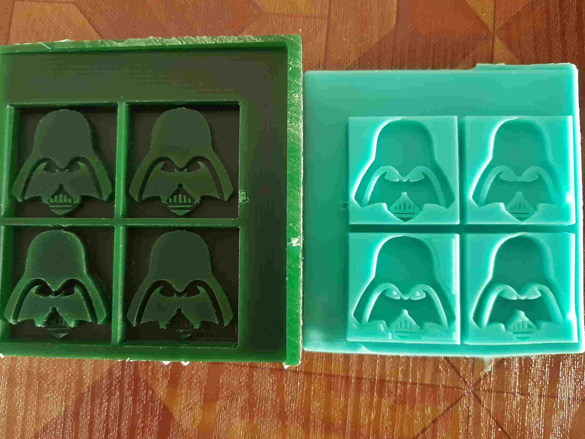
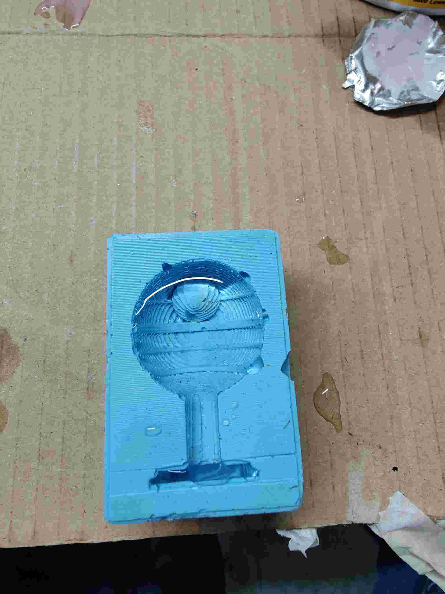
Creating the Negative Mold
Silicone rubber what I used comes from Smooth-On vendor
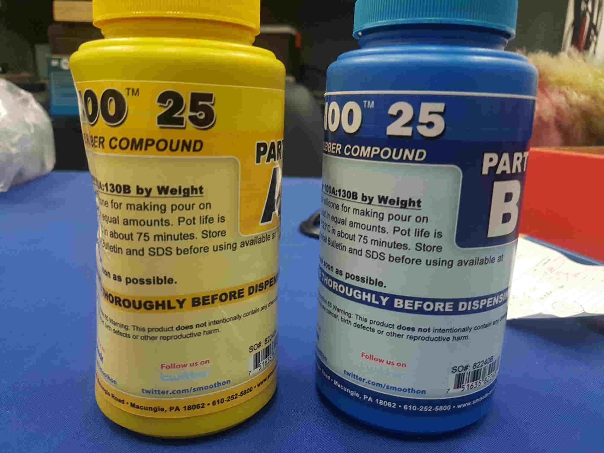
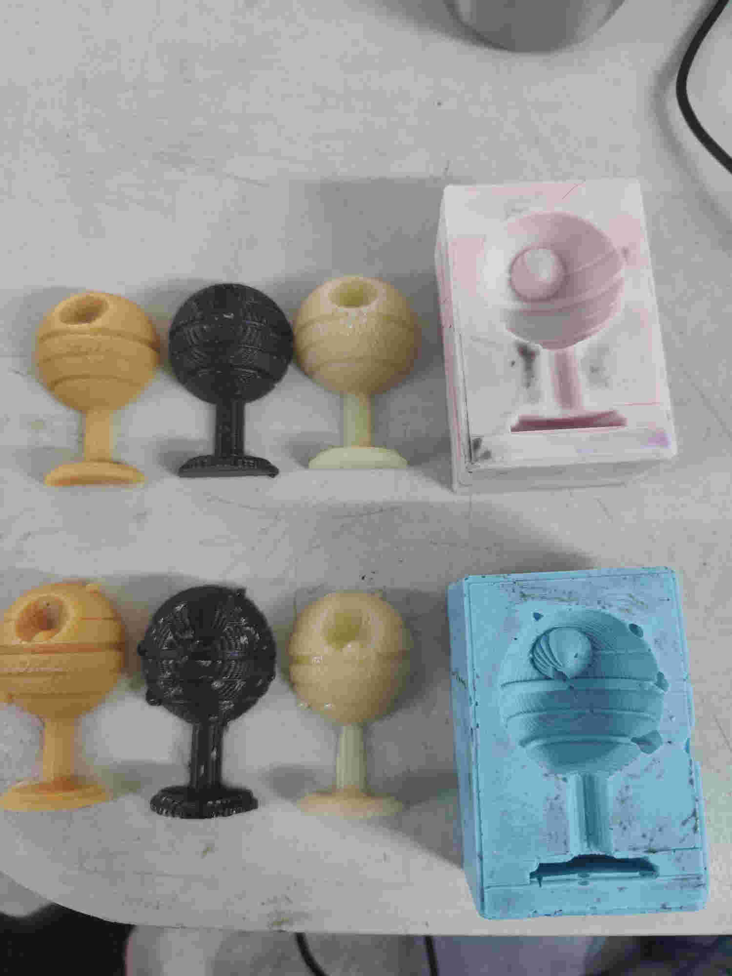
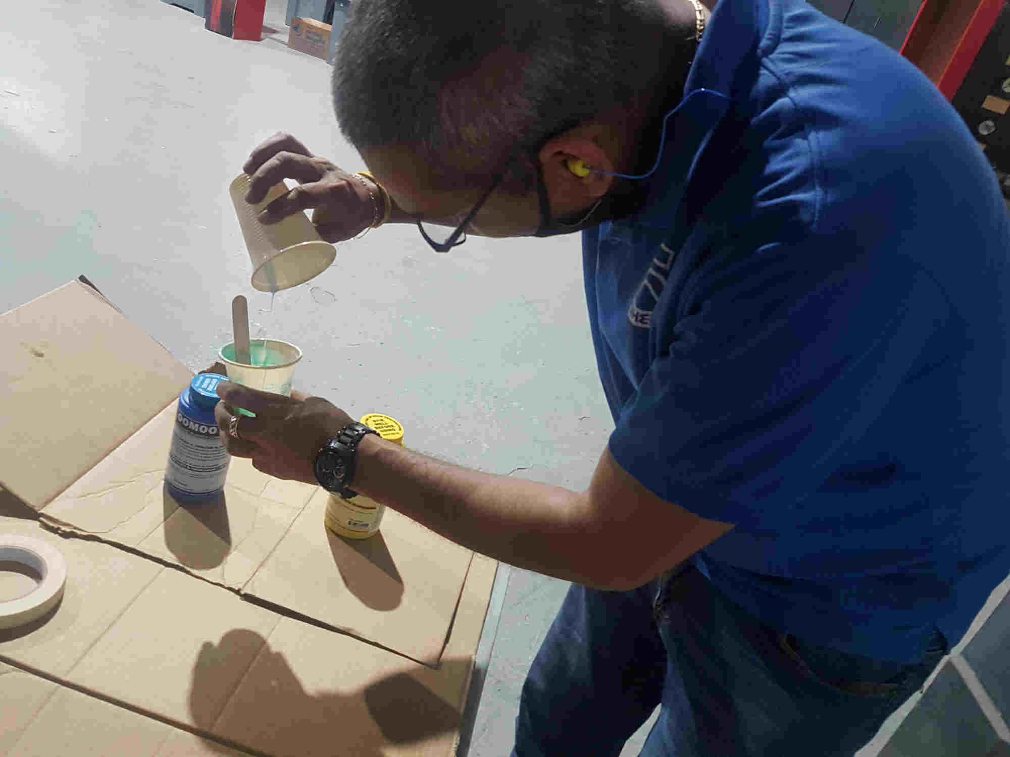
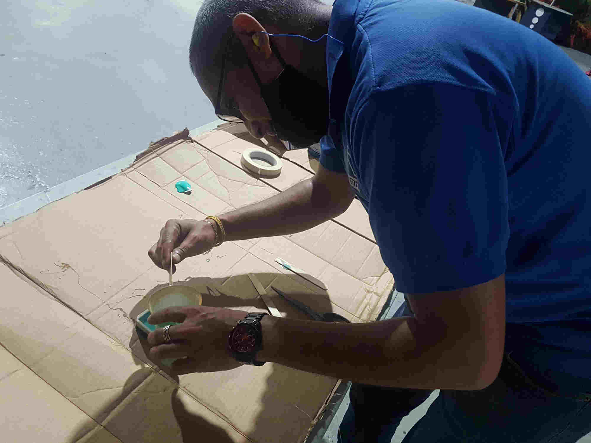
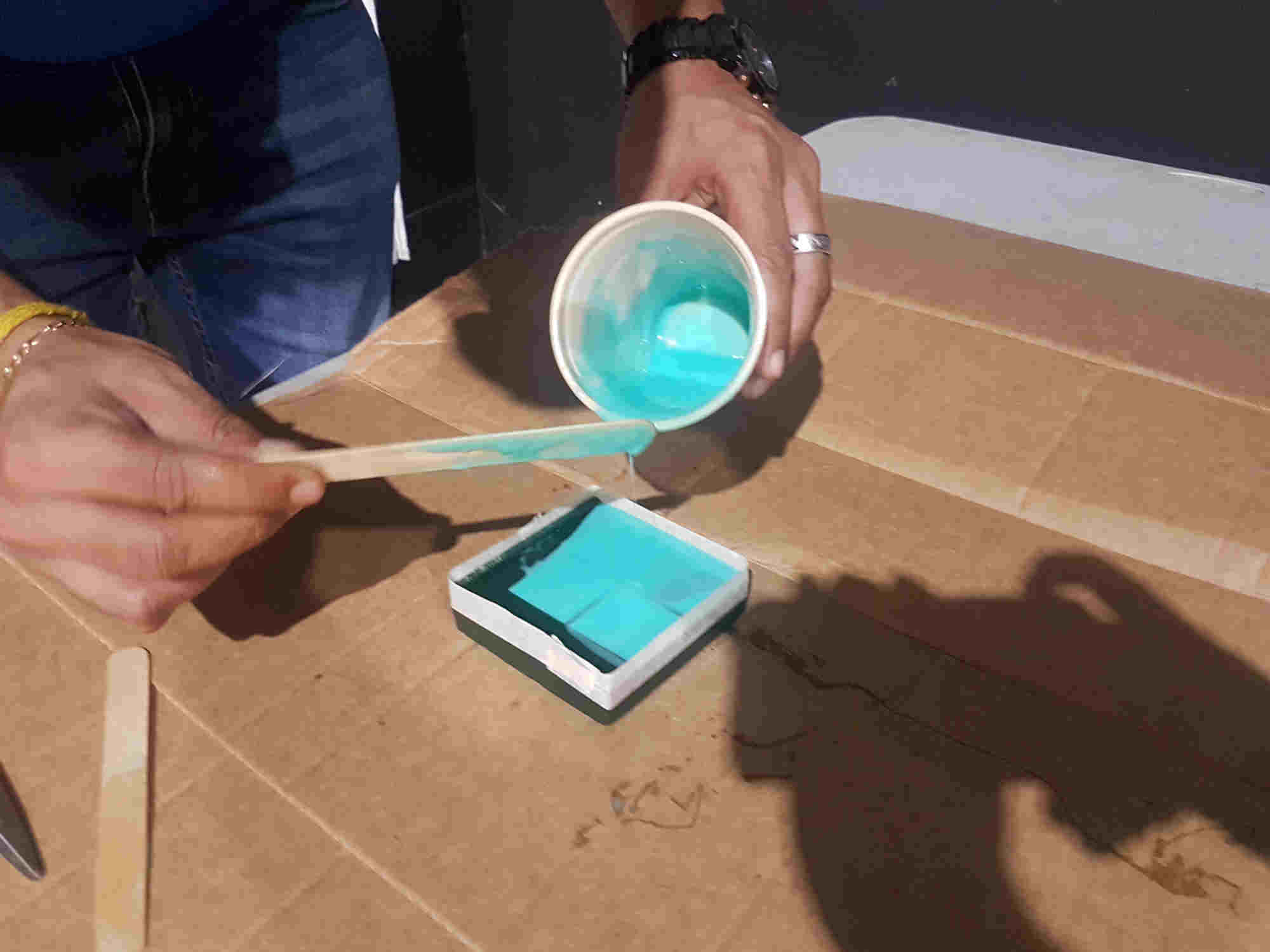
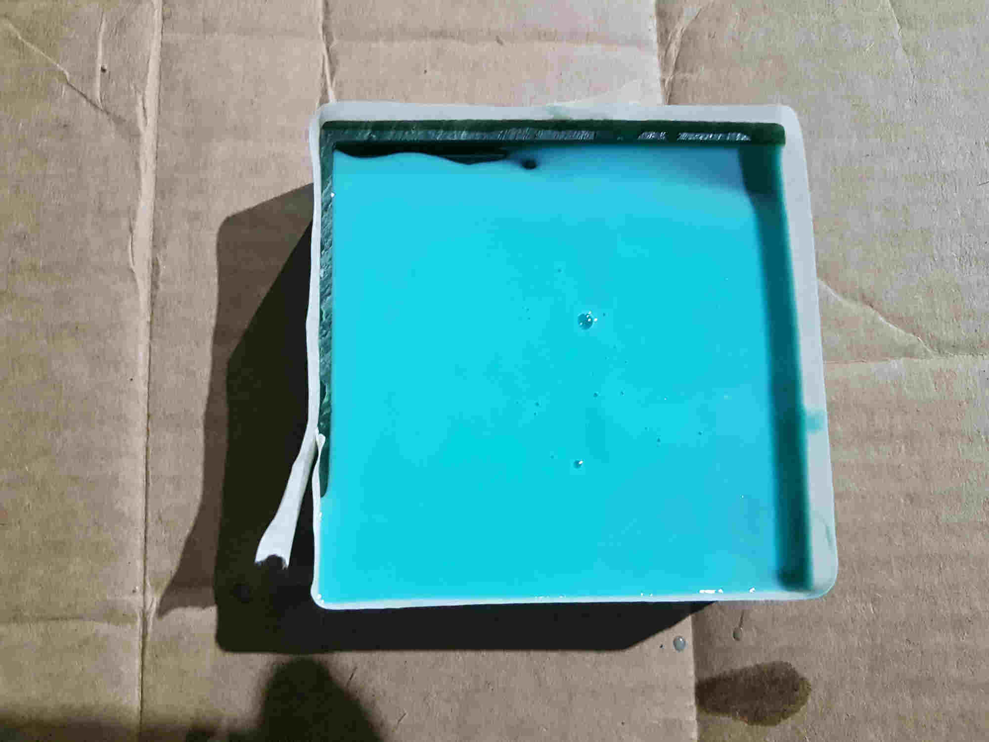
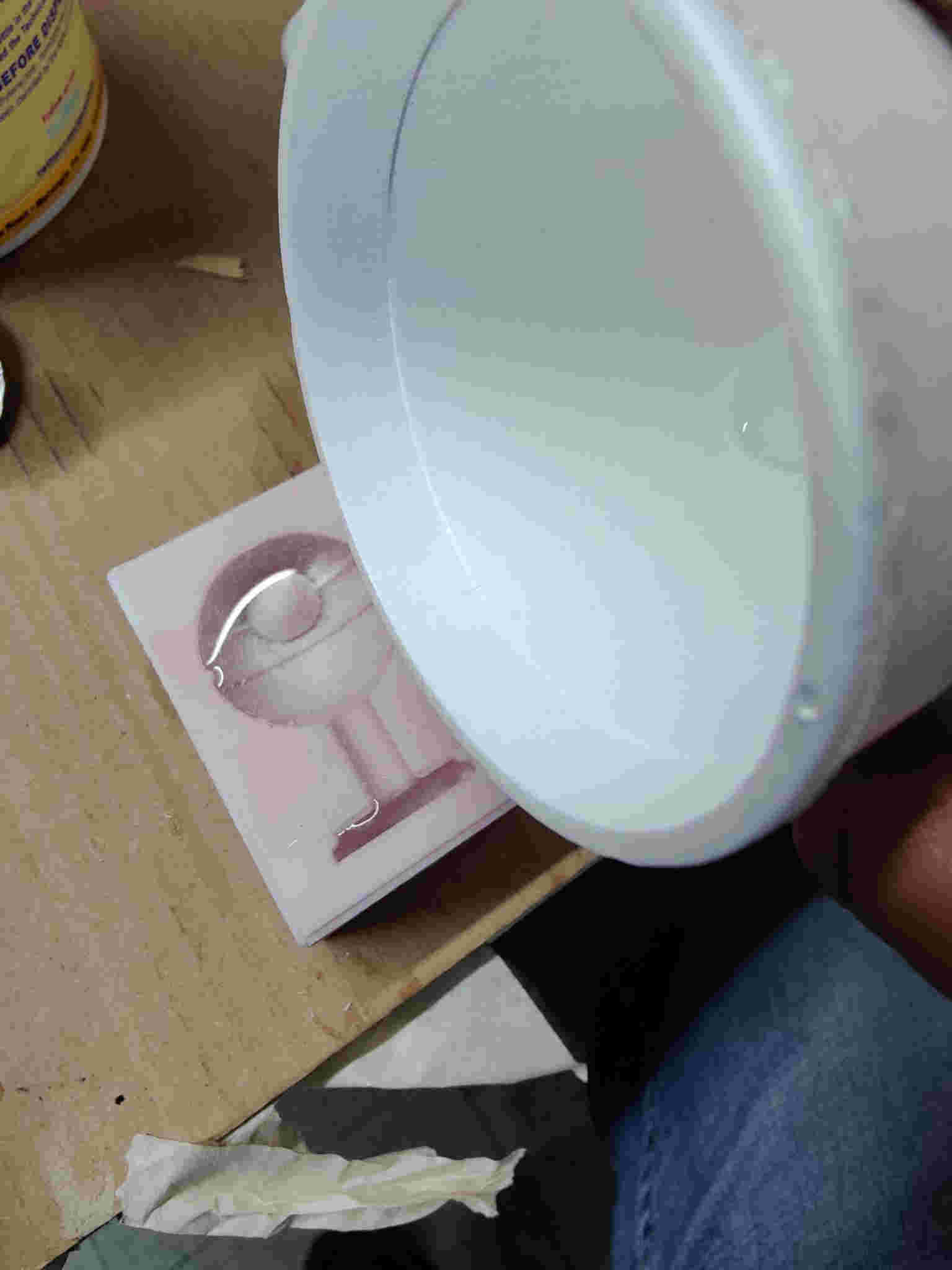
In the beginning I cleaned the wax molds from milling wax and determine the amount of both part A and part B needed. I mixed both chemicals together and stirring only in a circle. To prevent the formation of bubbles, then I filled it all slowly and evenly poured the mixer into the wax mold. After 30 minutes it was numb, but I waited about hour to be completely sure it was cured. Before removing it.

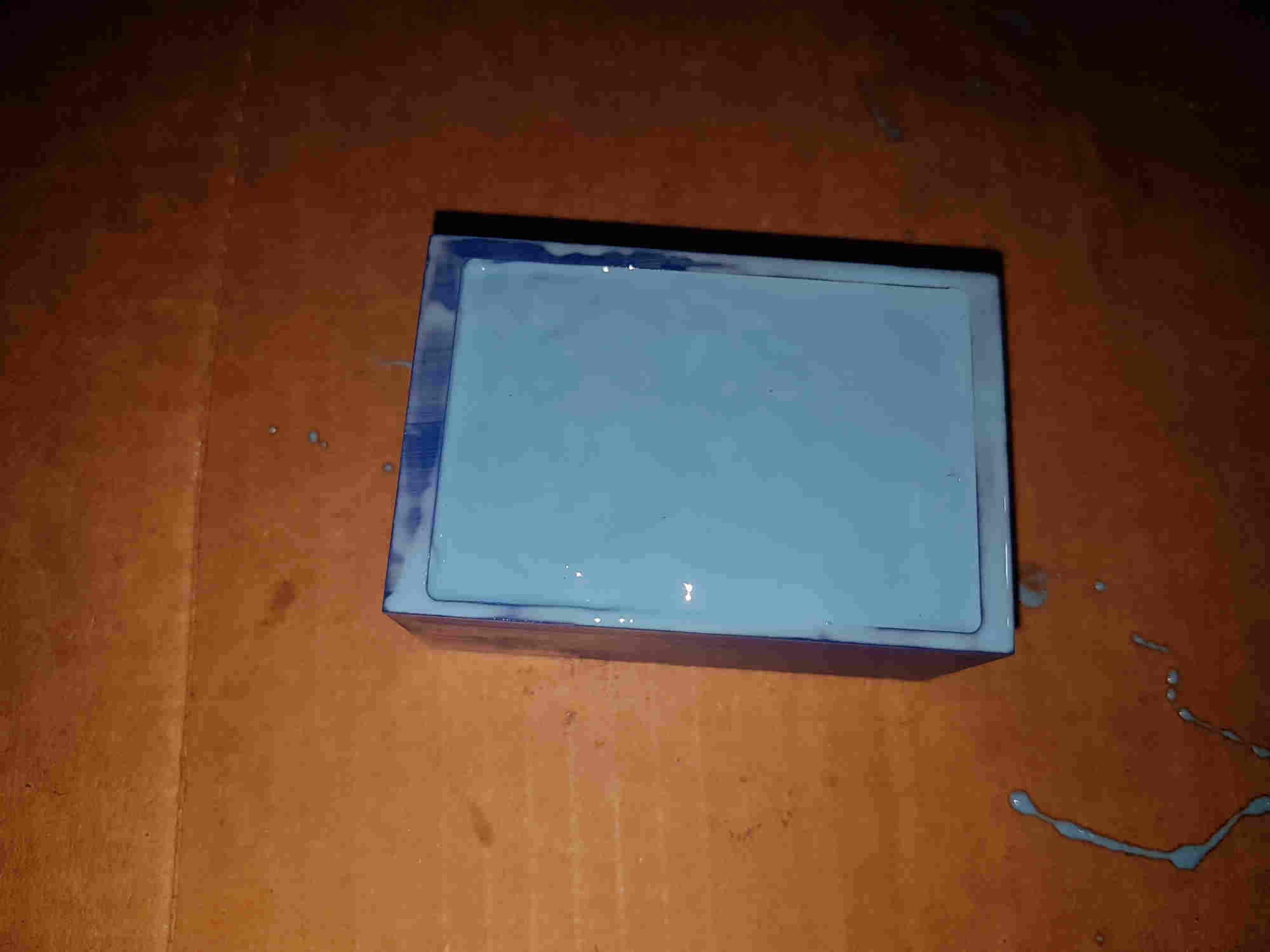
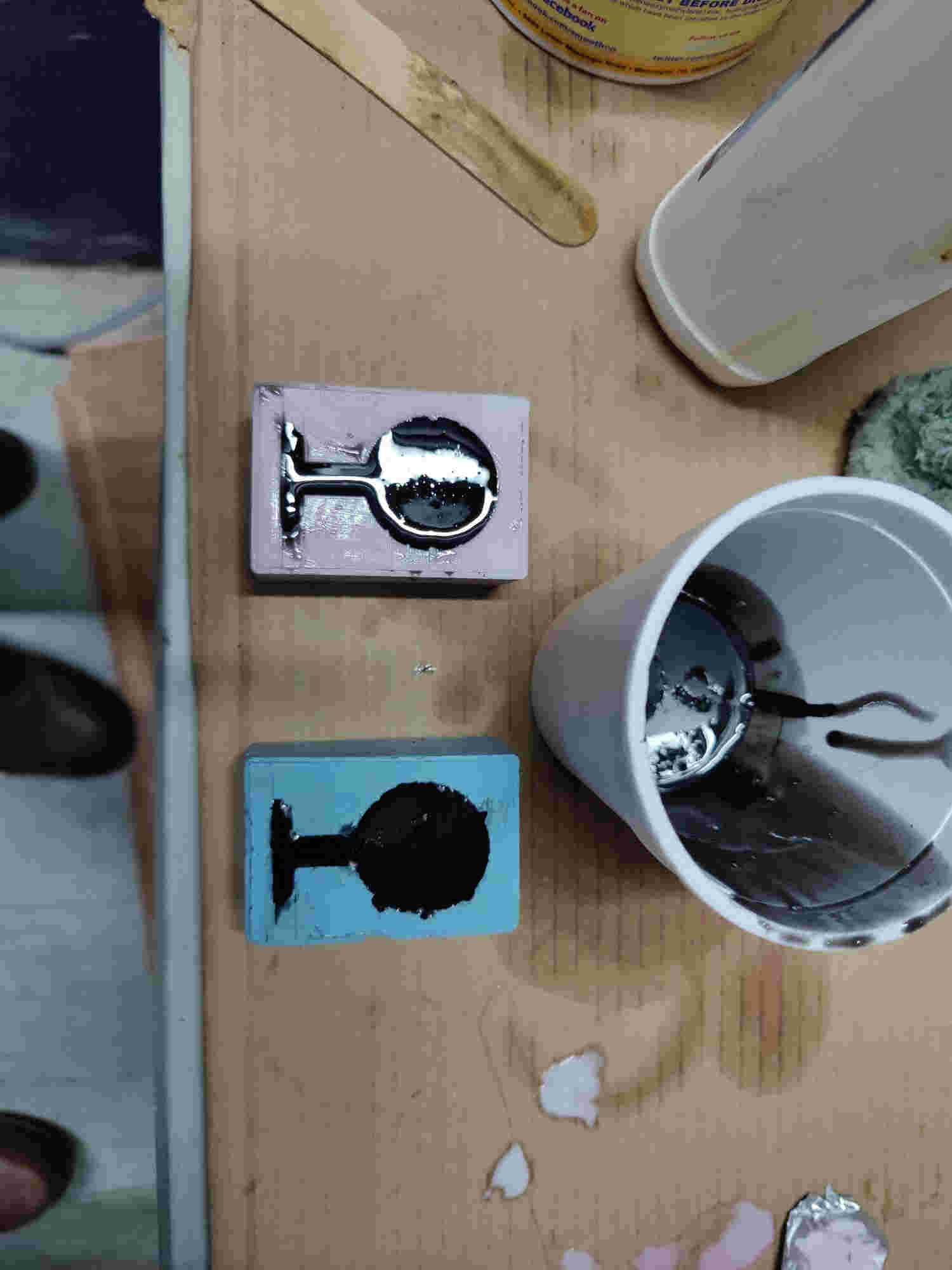
Casting
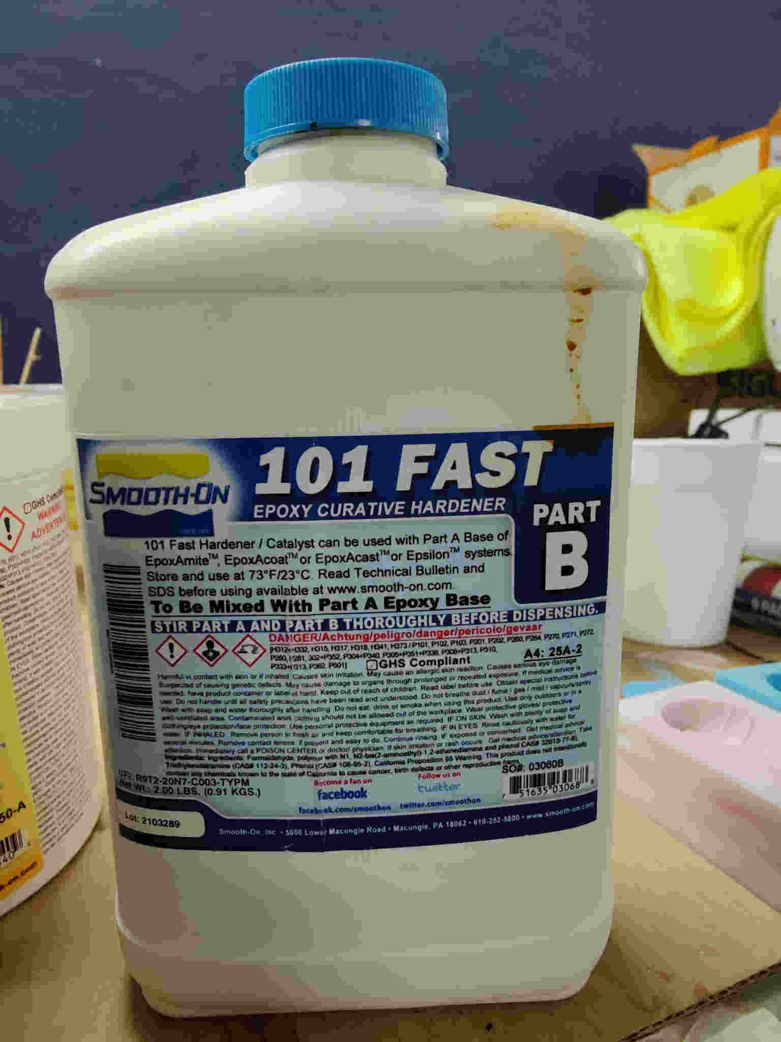
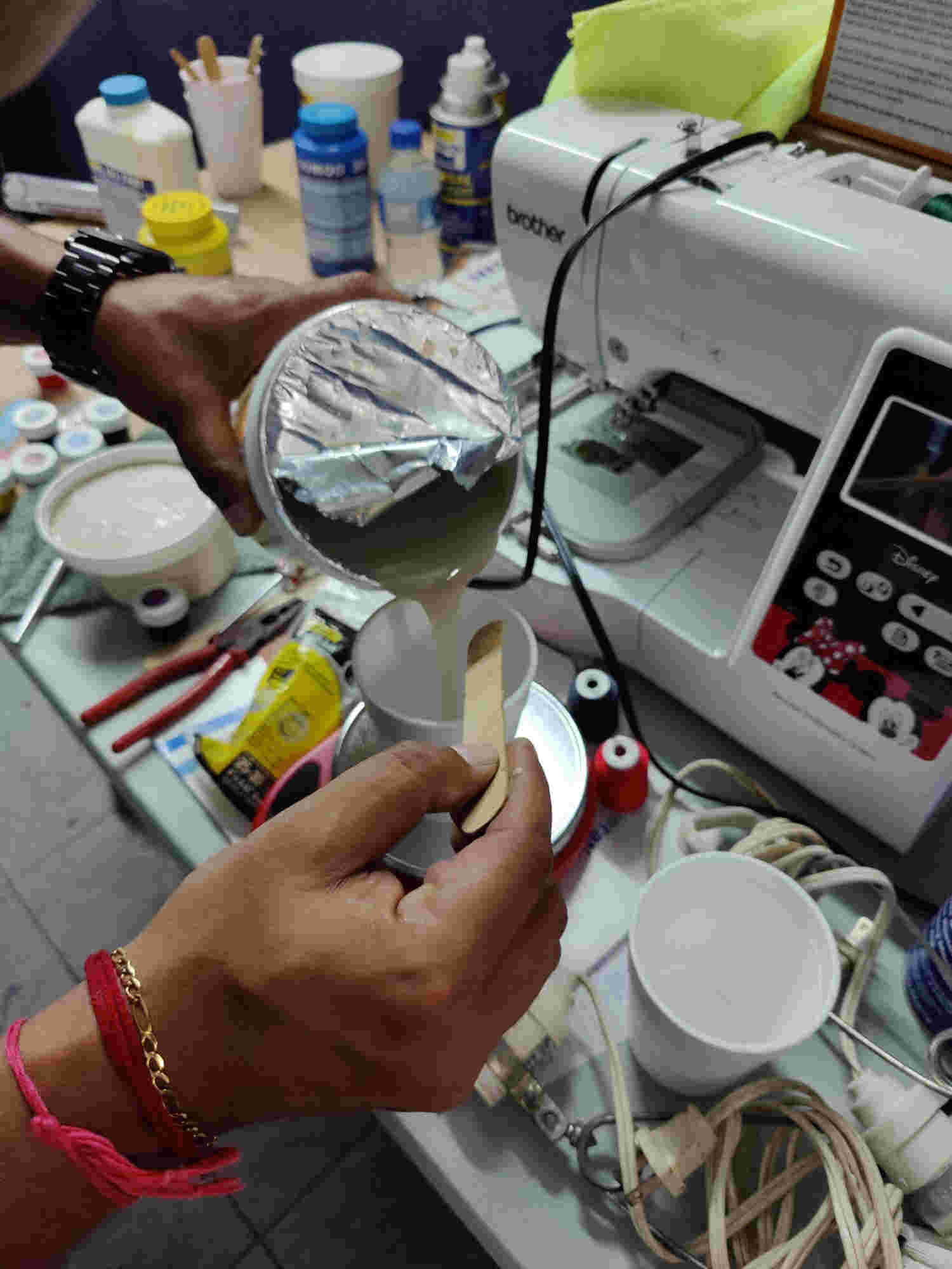
For the casting process I used the Epoxy Casting System from Smooth-On. It is a two part system comprising of EpoxA cast 650 and 101 Fast Epoxy Curative hardener

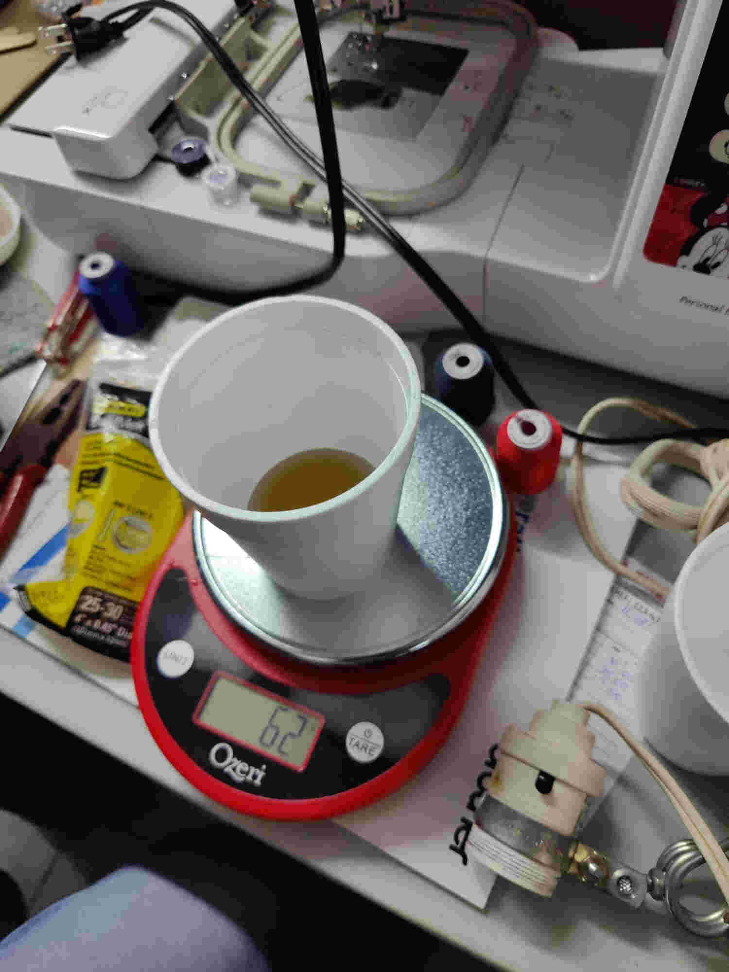
To determine the volume of Epoxy we require we simply poured water into the two negative molds they empty in to a cup and mark the level in the cup.
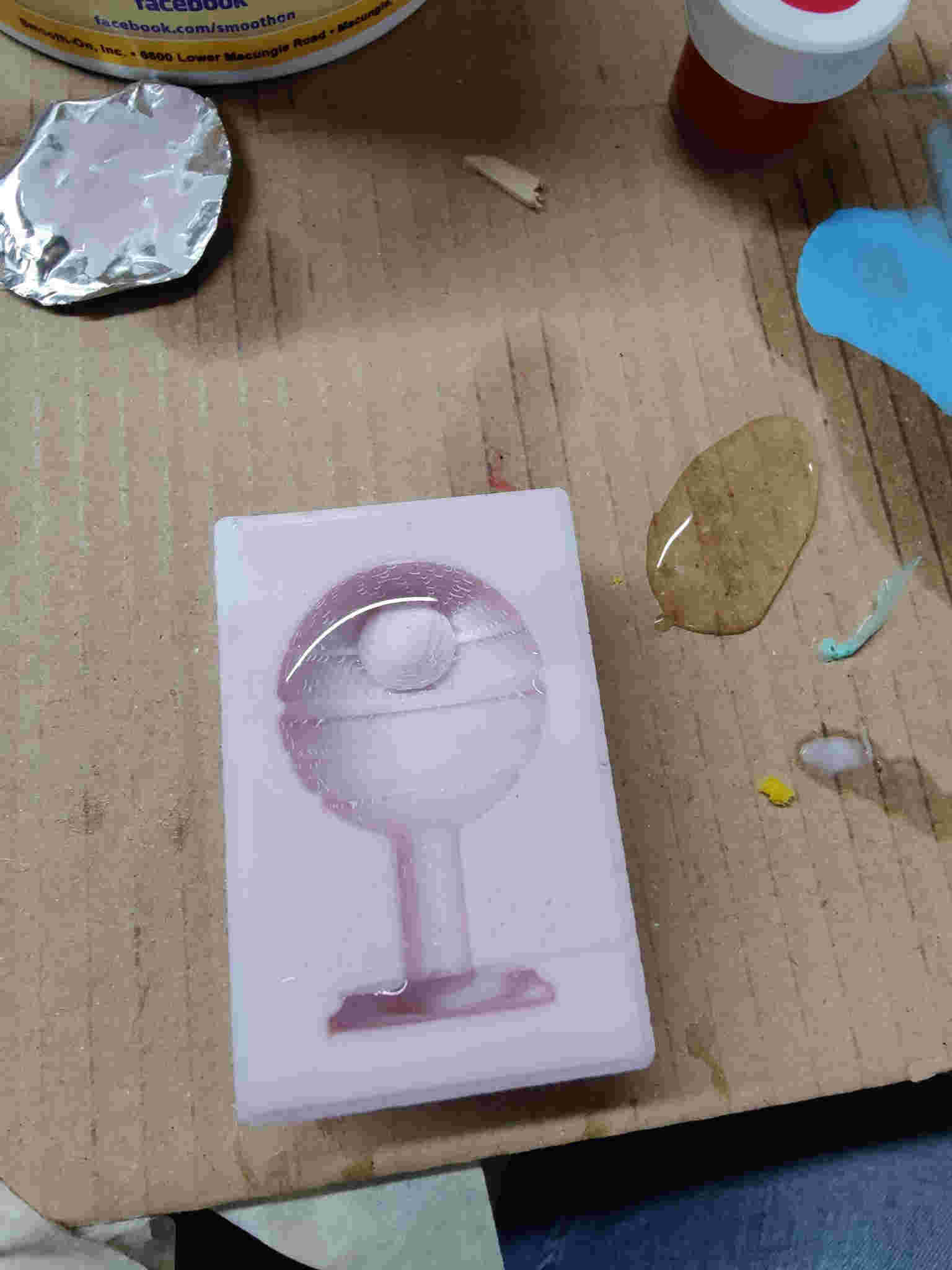

After pouring the EpoxA cast 650 Part A to the required level it was weighted. This because the 101 Fast Epoxy Curative hardener needed to be mix in at a 1 :10 weight ratio. This means for every 1g harder 10g epoxy. Then 1g of black color pigment was add To determine the volume of Epoxy we require we simply poured water into the two negative molds they empty in to a cup and mark the level in the cup.
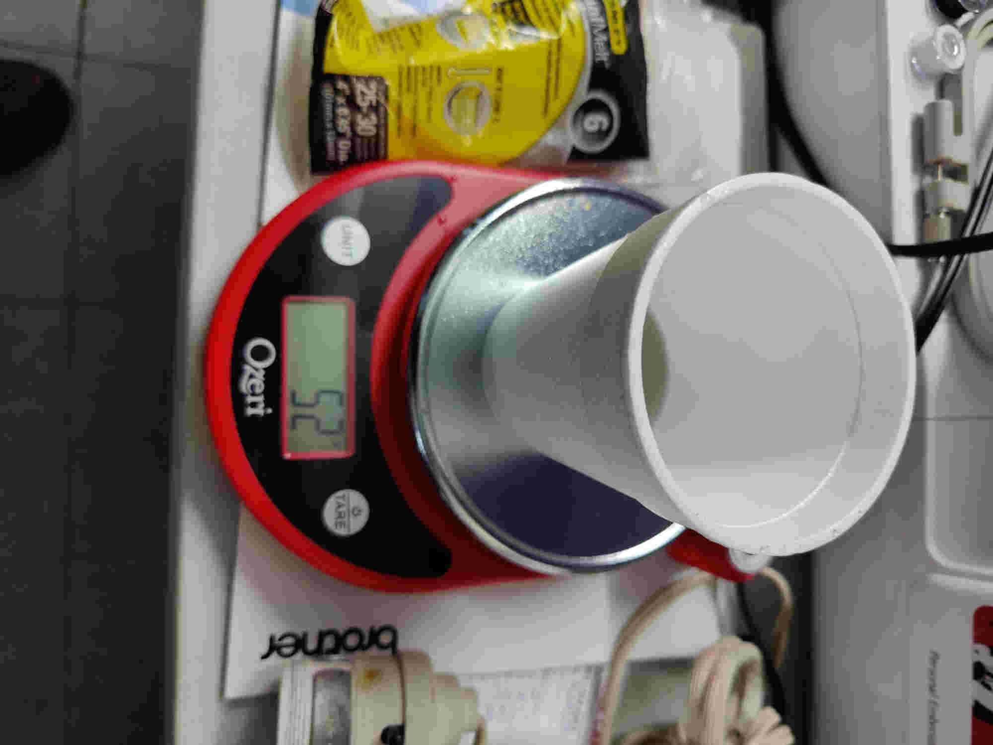
weight of epoxy
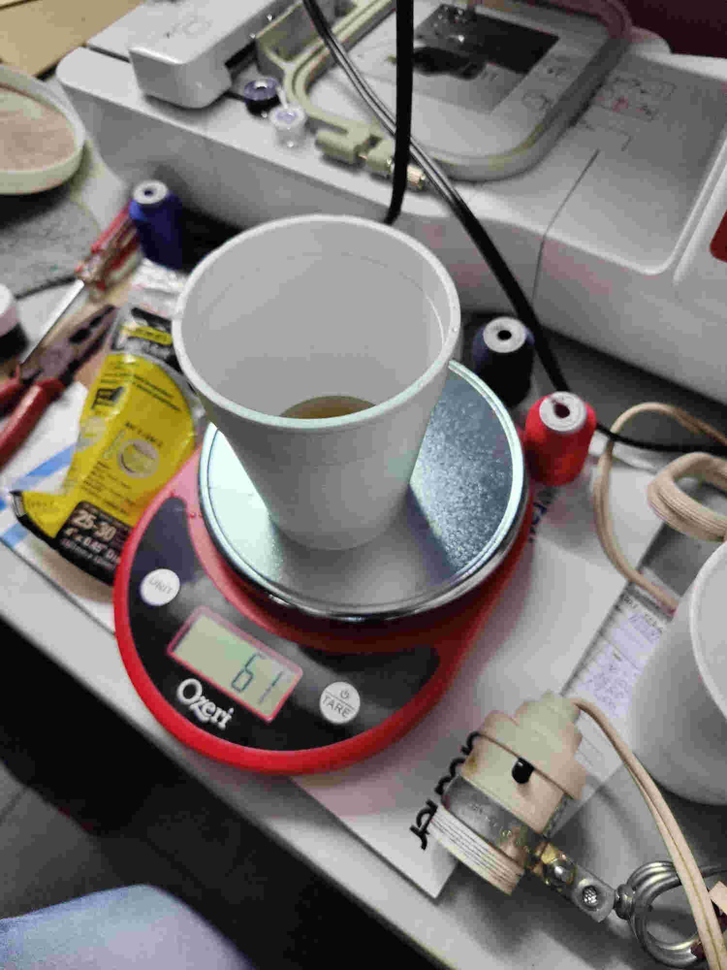
weight with hardener
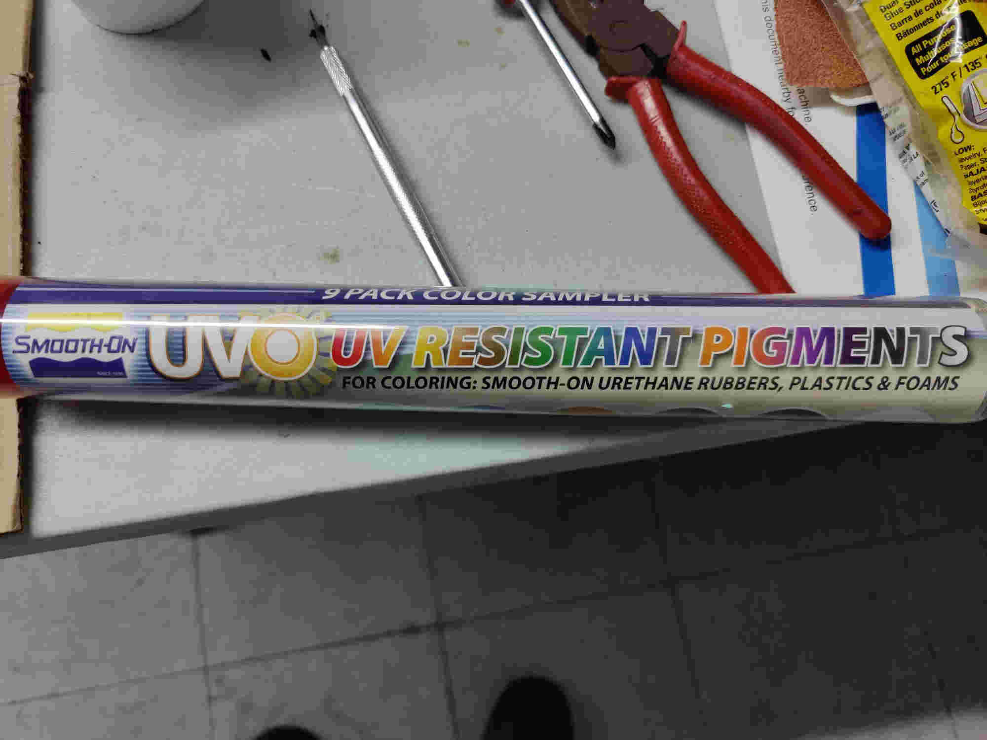
Colour pigment
Weight with colour pigment
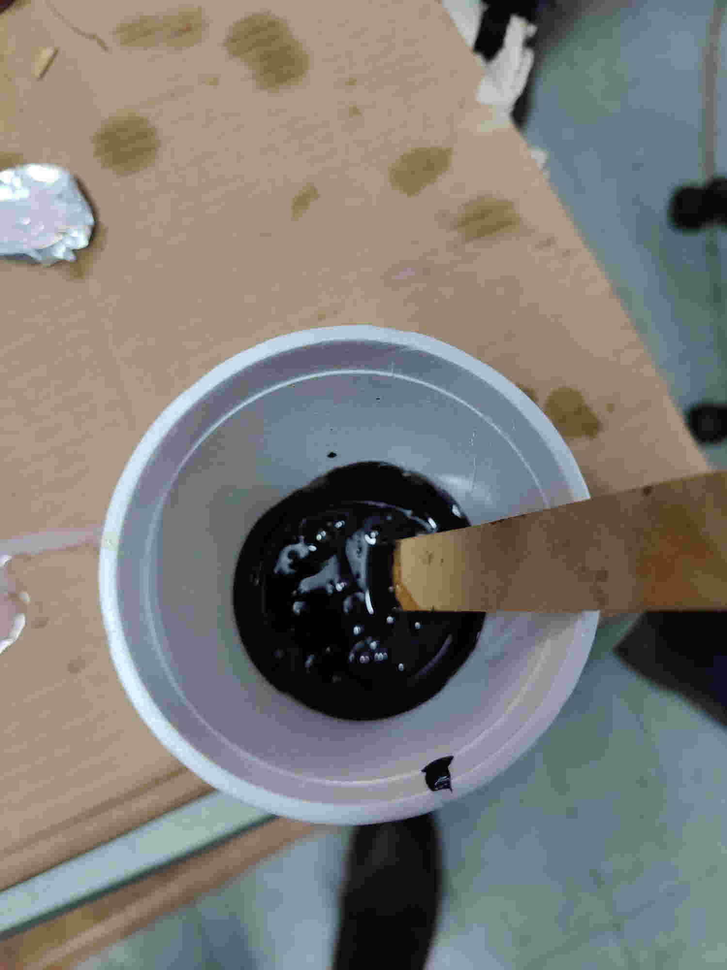
mix
weight of epoxy
weight with hardener
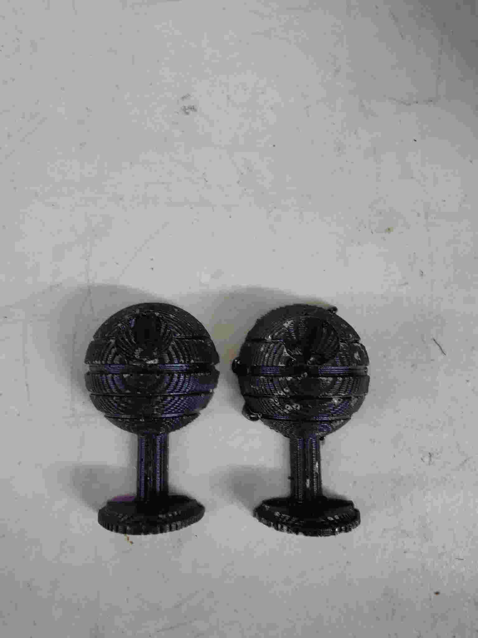
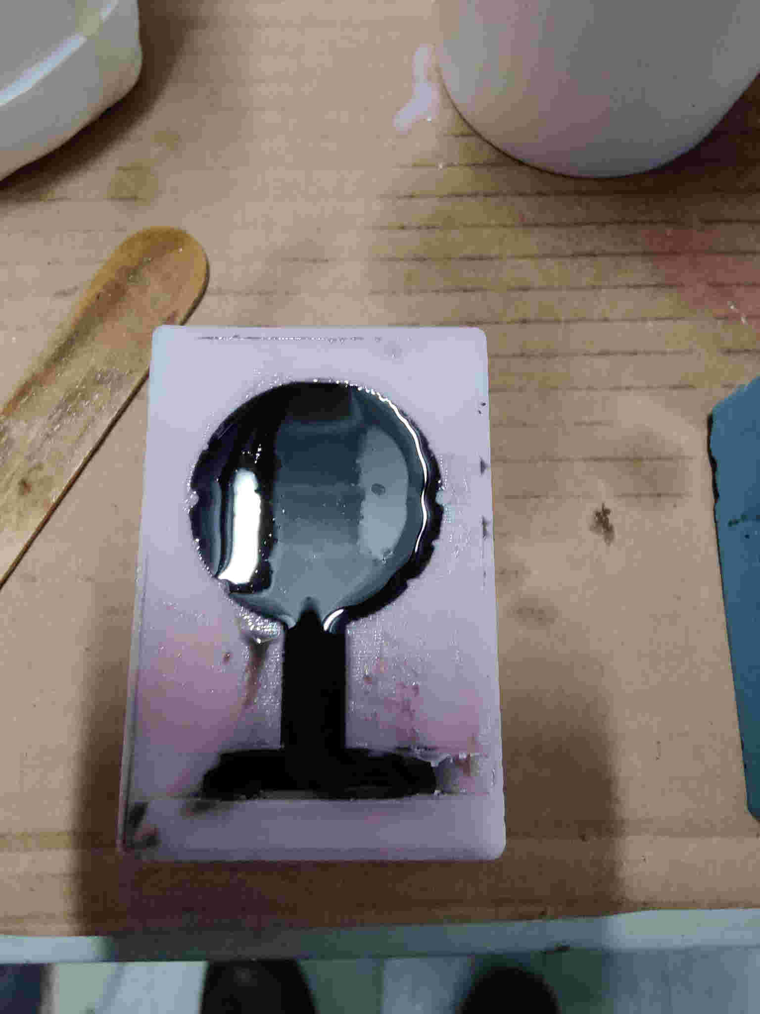
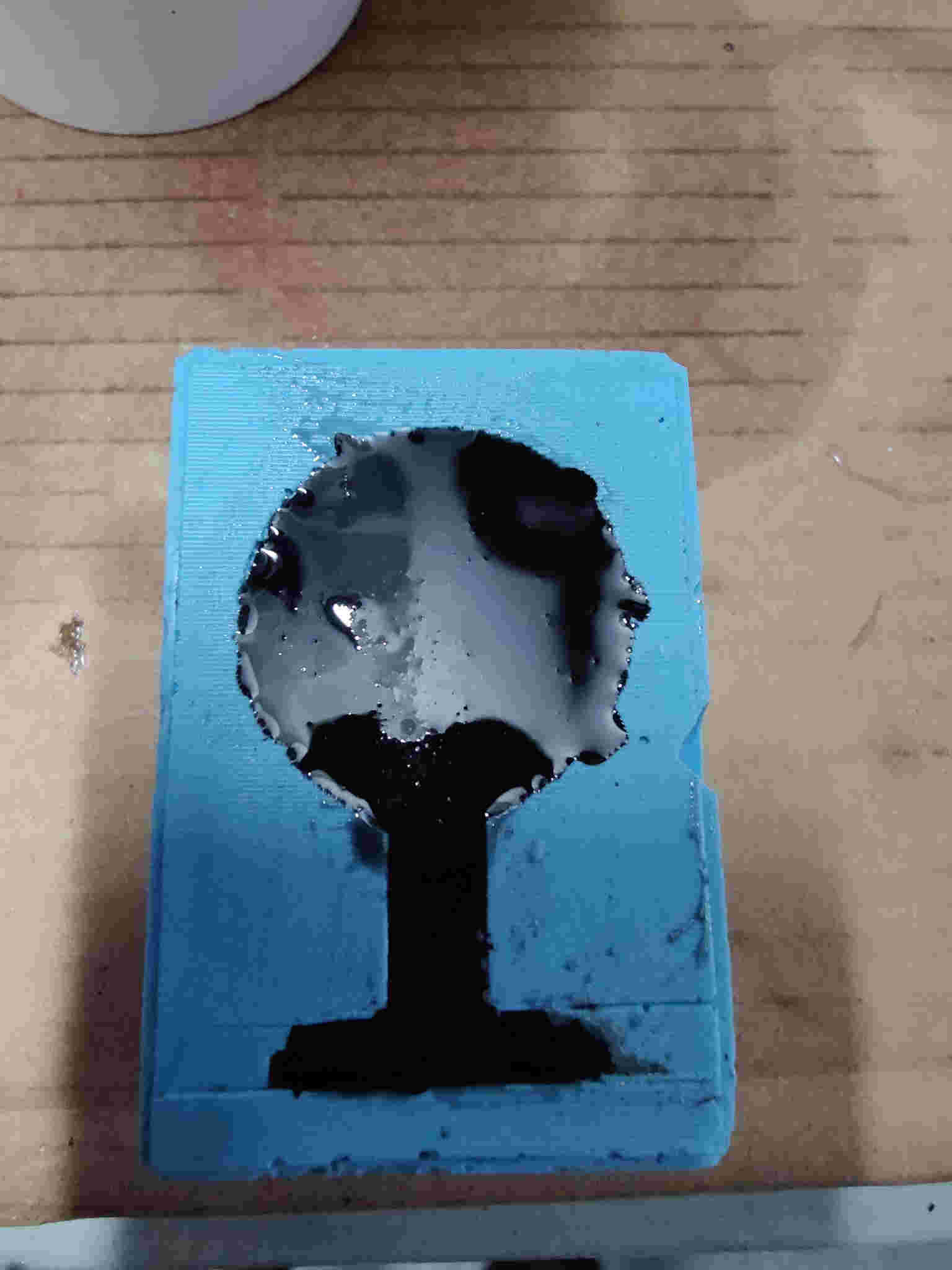
The rest of my team had extra epoxy cast mix left over from there casting so I just poured it my mold.