11.Output devices
Output devices take the signal from the process device of a system and turn it back into a physical or ‘real-world’ signal, such as light , sound or motion.
Light outputs:Light can be produced in different ways; a light-emitting diode (LED) is the most common component used for producing light.
Sound outputs: Sound can be produced using buzzers or speakers.
Motor outputs: Motors convert power into rotary motion, moving gears or wheels by turning a spindle linked to them. They are used in wind turbines, cars and trains.
Learning outcomes;
- Demonstrate workflows used in controlling an output device(s) with MCU board you have designed
Like the previous weeks , student are expected to complete two (2) categories of weekly assignment.
Group assignment:
-
Measure the power consumption of an output device
-
Document your work to the group work page and reflect on your individual page what you learned
Individual assignment:
- Add an output device to a microcontroller board you’ve designed and program it to do something
Group Assignment
For our Group assignment we had to Measure the power consumption of an output device and document our findings.
The Group Assignment page is as follows Link
Group Members:
-
Nervene Bhagwandass
-
Christopher Proute
-
Terrence Carew
-
James Khan
-
Ravi Baldeo
-
Marvin Holloway
Individual Assignment
For my individual assignment I modified my Electronic design week assignment to include two outputs ports for servo motors.
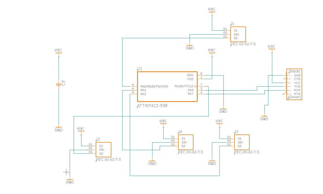
I began by modifying the schematic below by removing the switch , led and respective resistors
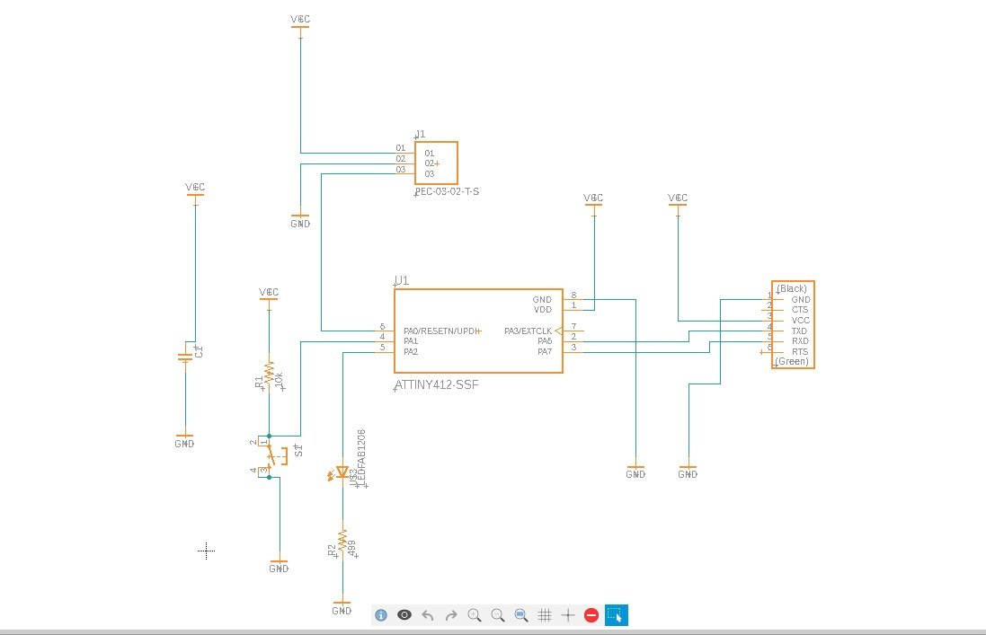
I then included two 3 position female comm ports on pin2 and pin 3
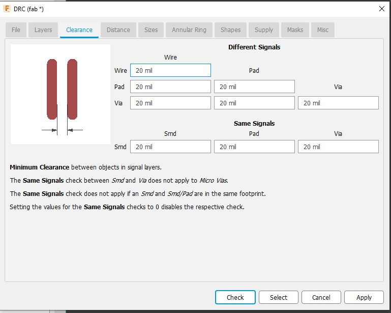
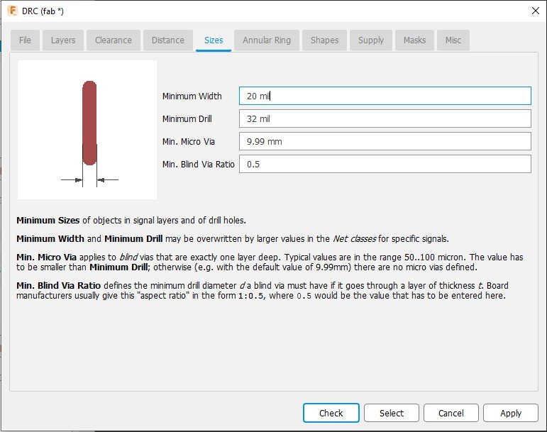
I then appealed the fab.dru rules with some modification to:
-
Clearance
-
Size
Changing the values from 16 mil to 20 mil
After auto routeing in Fusion this was the best layout giving.

Then exported the file to a dxf format to be imported into Carbide Create
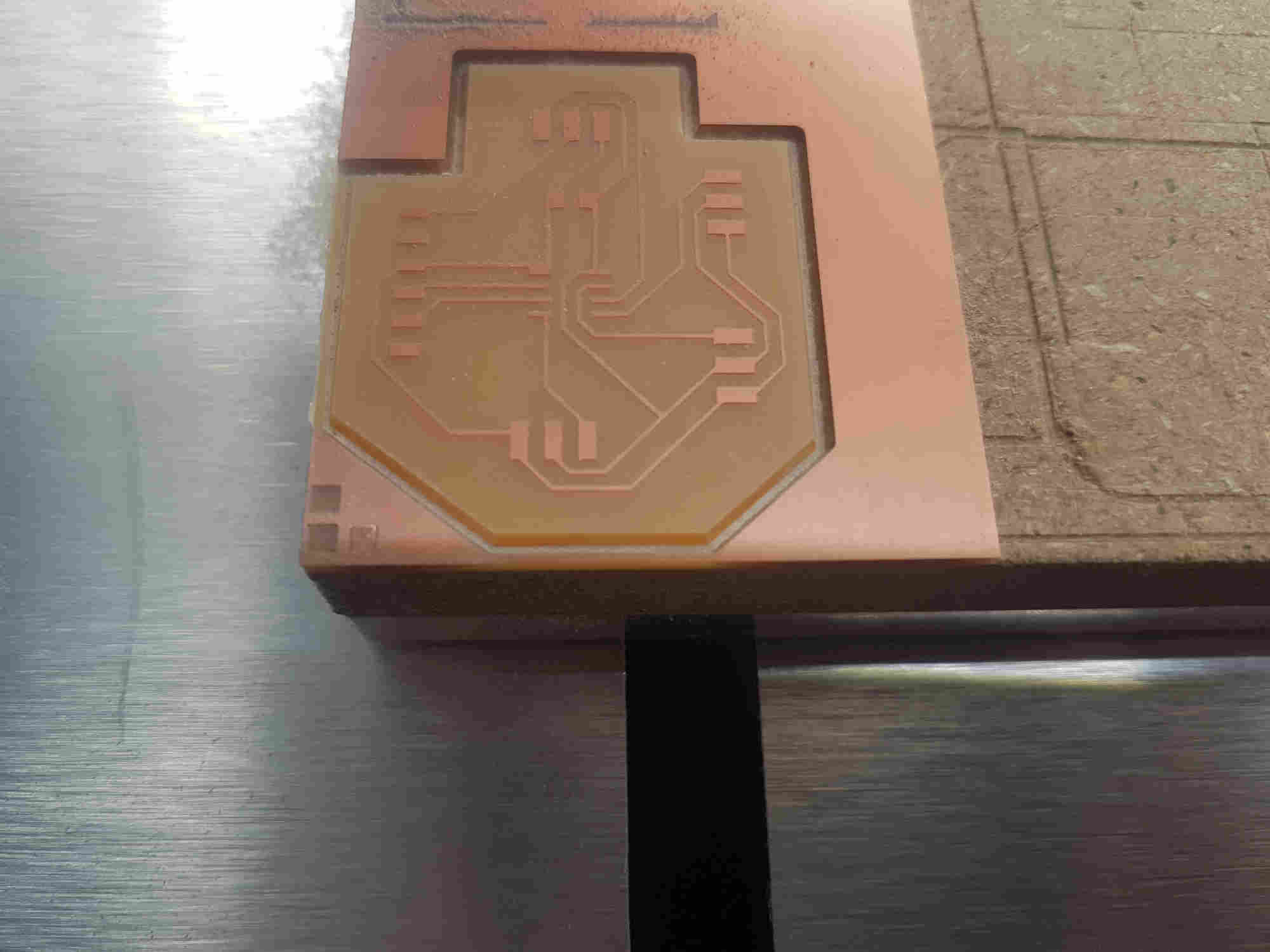
Milling and Soldering
Milling
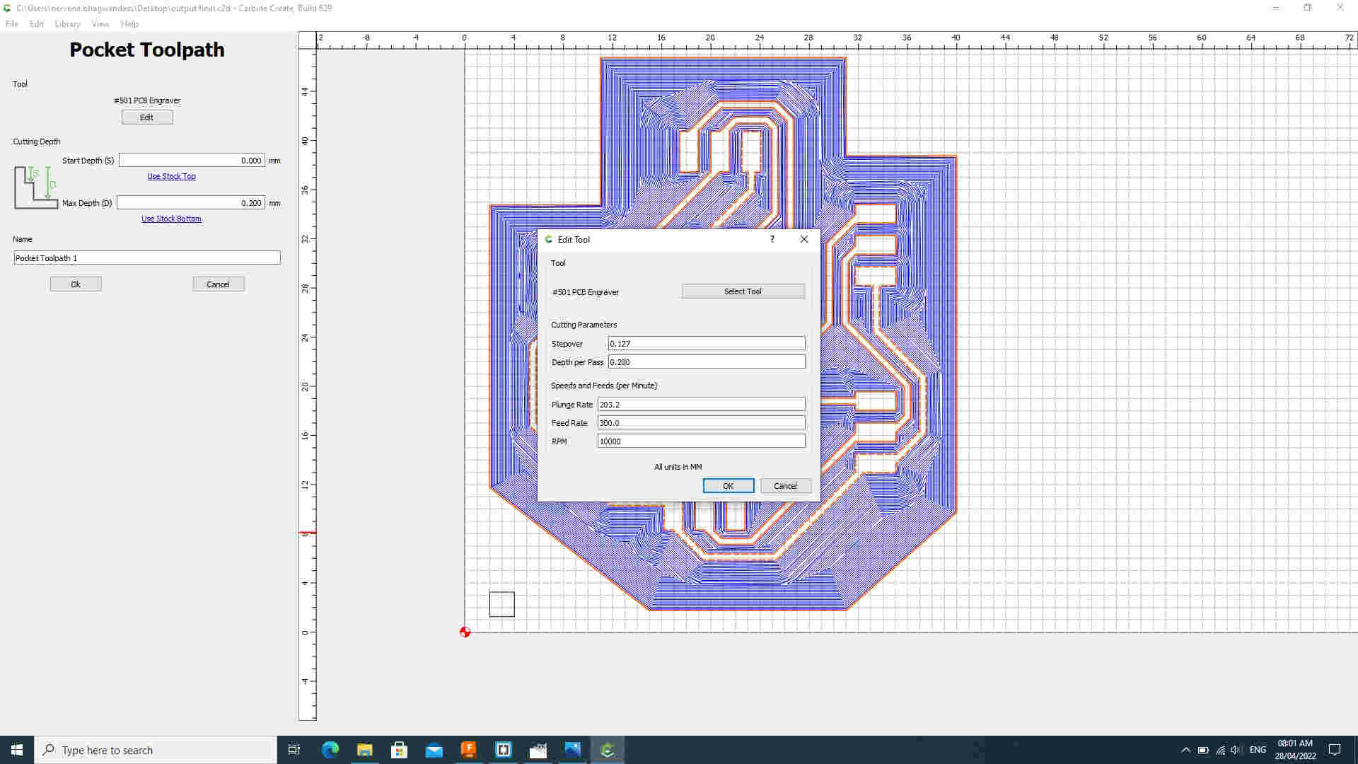
Imported the Schematic week 11v3 dxf file in to Carbide Create and setup the tool paths Pocketing tool path
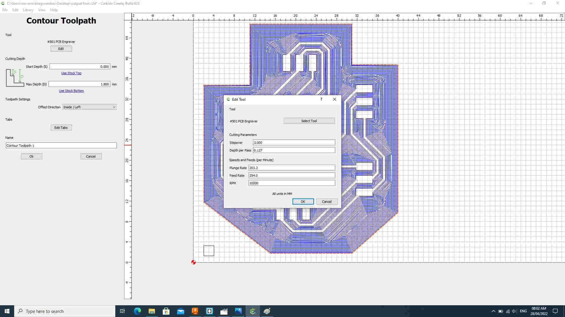
Contouring tool path
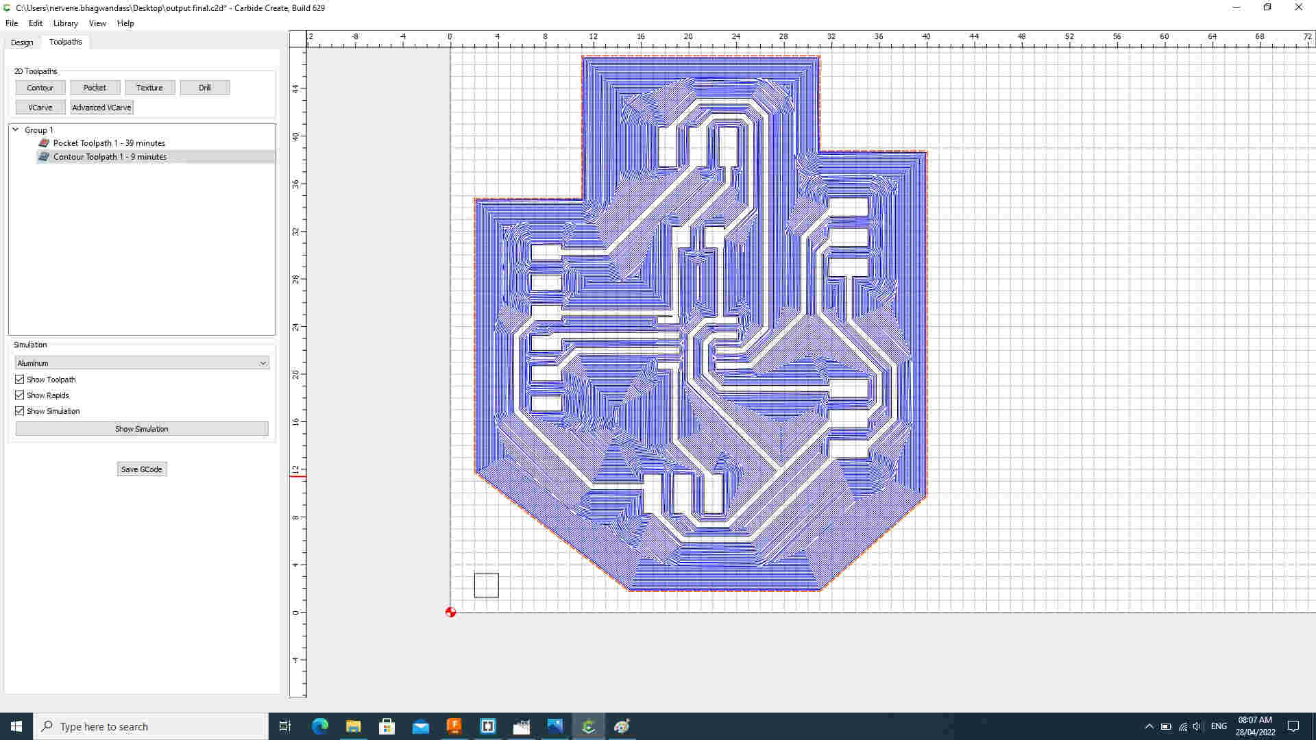
Total time estimated
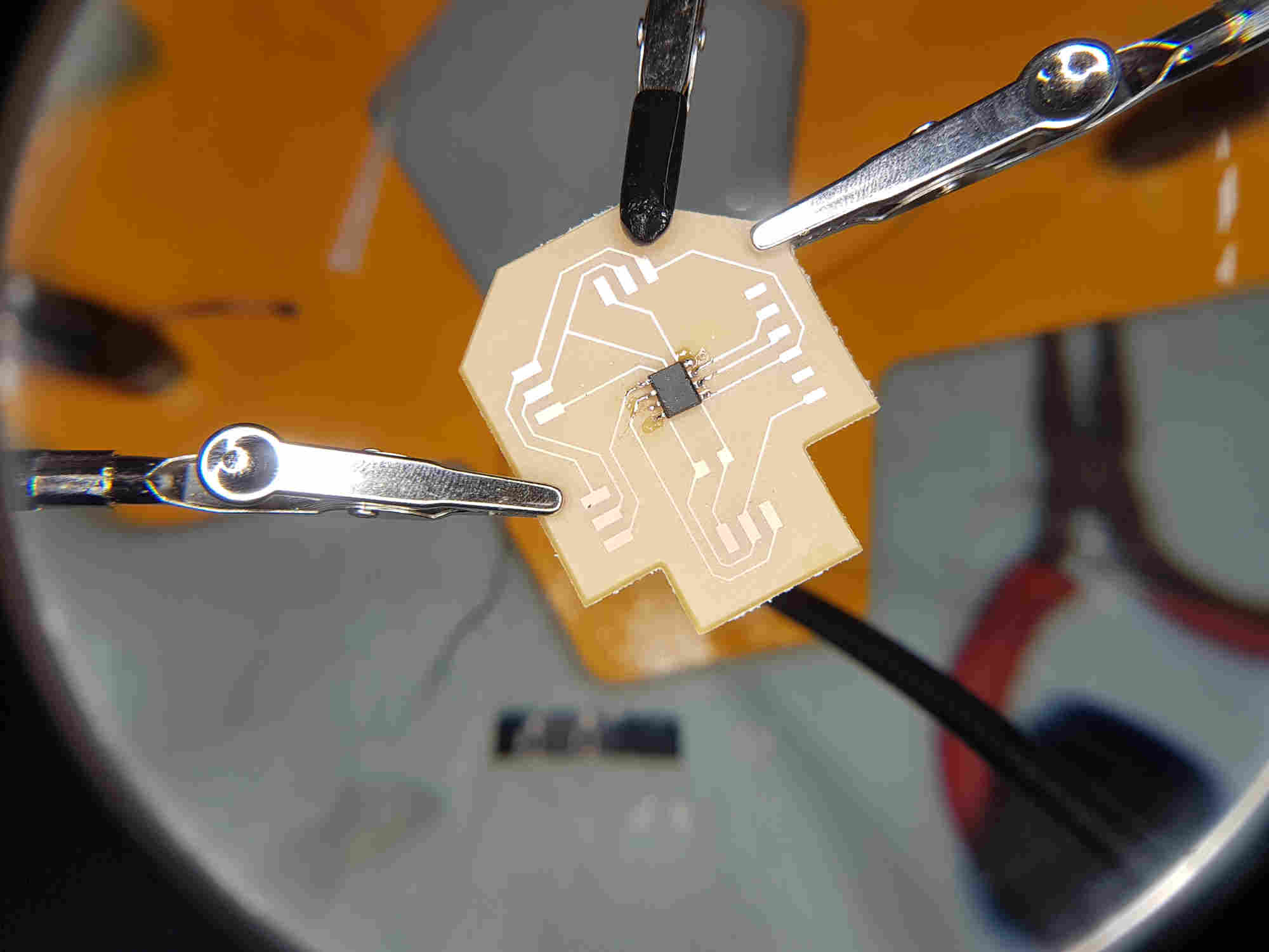
Soldering
Components need for the PCB board
-
Attiny 412 chip
-
One unpolarized capacitor, 1uF
-
FTDI connector
-
UPDI connector
-
3 pos female comm ports


PROGRAMMING PROCESS
-
More about ATtiny & Arduino IDE pinouts relationship look at Embedded Programming week.
-
First of all I programmed a Communication test to be sure that chip works from the Electronic design week.
I then copied Neil tiny412 servo hello world code and modified the servopin0 and servopin1 to suit my pin config output.
//

// hello.servo.t412

//

// tiny412 servo hello-world

//

// Neil Gershenfeld 11/16/21

//

// This work may be reproduced, modified, distributed,

// performed, and displayed for any purpose, but must

// acknowledge this project. Copyright is retained and

// must be preserved. The work is provided as is; no

// warranty is provided, and users accept all liability.

//

#include <Servo.h>

#define delaytime 5 // delay time between steps (ms)
#define servopin0 2  // servo 0 pin (PA2)
#define servopin1 3 // servo 1 pin (PA1)


Servo servo0,servo1; //declare servos
int angle = 0;

void setup() {
   servo0.attach(servopin0); // attach servos to pins
   servo1.attach(servopin1);

   }

void loop() {
   for (angle = 0; angle <= 180; ++angle) { // step servo 0
      servo0.write(angle);
      delay(delaytime);
      }
   for (angle = 0; angle <= 180; ++angle) { // step servo 1
      servo1.write(angle);
      delay(delaytime);
      }

   for (angle = 180; angle >= 0; --angle) { // step both
      servo0.write(angle);
      servo1.write(angle);
      delay(delaytime);
      }
   }
