3. Computer Aided Design
Computer-Aided Design ” CAD” is the use of computers to create 2D and 3D designs. Common types of CAD include two-dimensional layout design and three-dimensional modeling.
2D CAD has many applications, but it is commonly used to design vector-based layouts. For example, architects may use CAD software to create overhead views of building floor plans and outdoor landscapes. These layouts, which contain vector graphics, can be scaled to different sizes, which may be used for proposals or blueprints. 2D CAD also includes drawings, such as sketches and mockups, which are common at the beginning of the design process.
3D CAD is commonly used in developing video games and animated films. It also has several real-world applications, such as product design, civil engineering, and simulation modeling. 3D CAD includes computer-aided manufacturing (CAM), which involves the actual manufacturing of three-dimensional objects.
Week 03
Learning outcomes
•   Evaluate and select 2D and 3D software

•   Demonstrate and describe processes used in modeling with 2D and 3D
     software
Project
My final project requires a wooden enclosure and a compression bumper being made. I decided on capitalizing on this week’s lesson and began designing first draft in 2D wooden enclosure and a 3D compression bumper that would be 3D printed. Some major aspects I had to determine before getting into the design was:
    •   Type of box (with fingers or not)

    •   Lengths

    •   Widths

    •   Heights

    •   Material thickness
There are a lot of box generators online, which I used to get a conceptal idea of the box.
Evaluate and select 2D & 3D software
There were many options presented in class but after reviewing the ones listed below
| Software | Pros | Cons |
| TinkerCAD |
- Simple 3D tools
- Free and online and accessible - Has tutorials - Make 3D printing files - Learn basic CAD skills |
- Best for simple parts - Seems more of a toy compared to more professional software - Hard to tell measurements sometimes |
| FreeCAD | - It is free and open-source - It is lighter that other similar software - parametric design | - The learning curve of this software is quite difficult |
| Inkscape | - It is free and open-source - Creating vector images and conversion to this format - Editing images with many cool tools | - Adding for tools as in paid products - Can be tricky to get the hang of at first - Require reading documentation |
| AutoCAD | - 2D & 3D Drafting - Its interface is user-friendly - Boundless area to create and design - Free for students and teachers | - Payed software - PC require high spec |
I decided to use AutoCAD for 2D and 3D (until I get the AutoCAD fusion 360 license )
2D Design
Inkscape
Inkscape is an open source vector graphics editor(free). It offer a lot of features similar to Corel Draw and others. It uses vector graphics to allow for sharp printouts and renderings at unlimited resolution and is not bound to a fixed number of pixels like raster graphics.
Download and install Inkscape
I try out going from a raster to a vector image. For the original images ( You may see alot of Star Wars 😂)
Download and then import image into Inkscape.

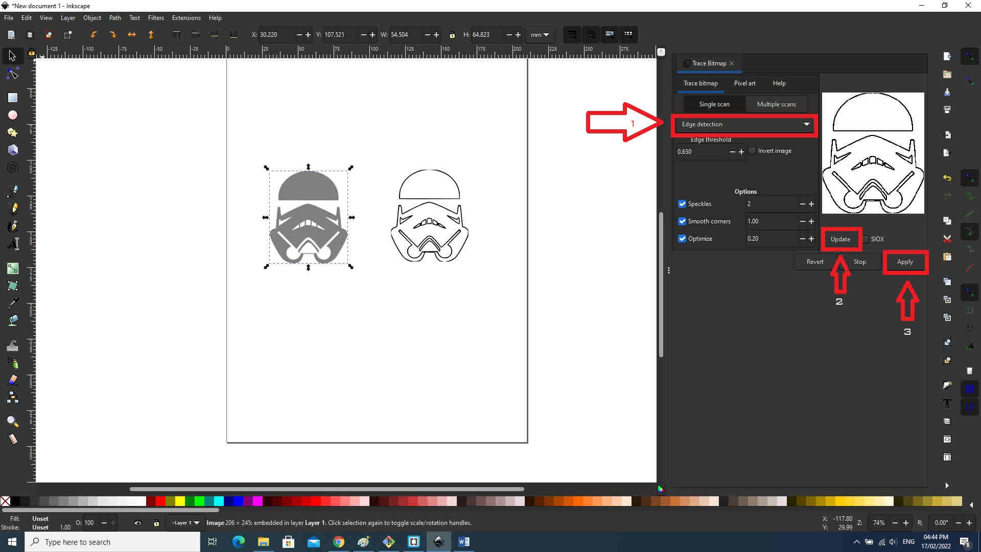
I used the path function -> Trace Bitmaps.
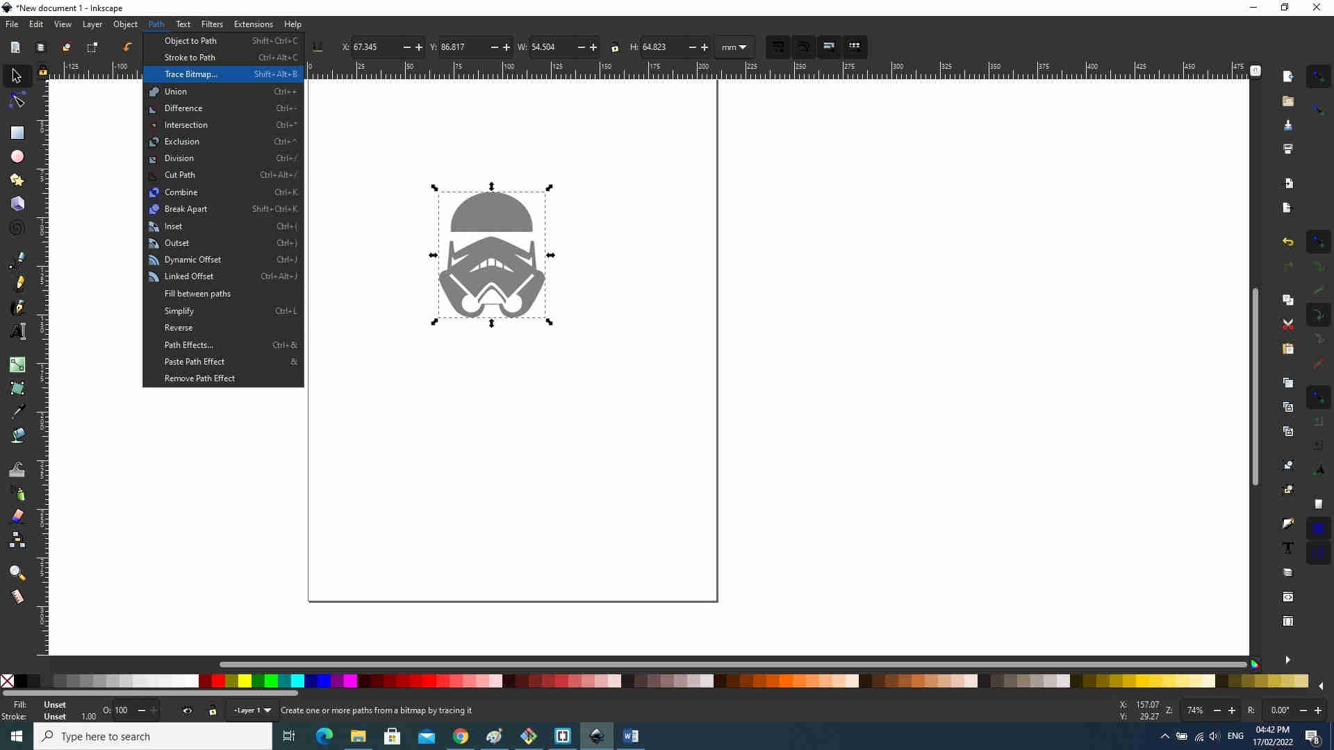
- Edge detection>update (for a preview)>apply
AutoCAD
Download and install AutoCAD. Fortunately, AutoCAD was already installed on my system.
Setting up the drawing
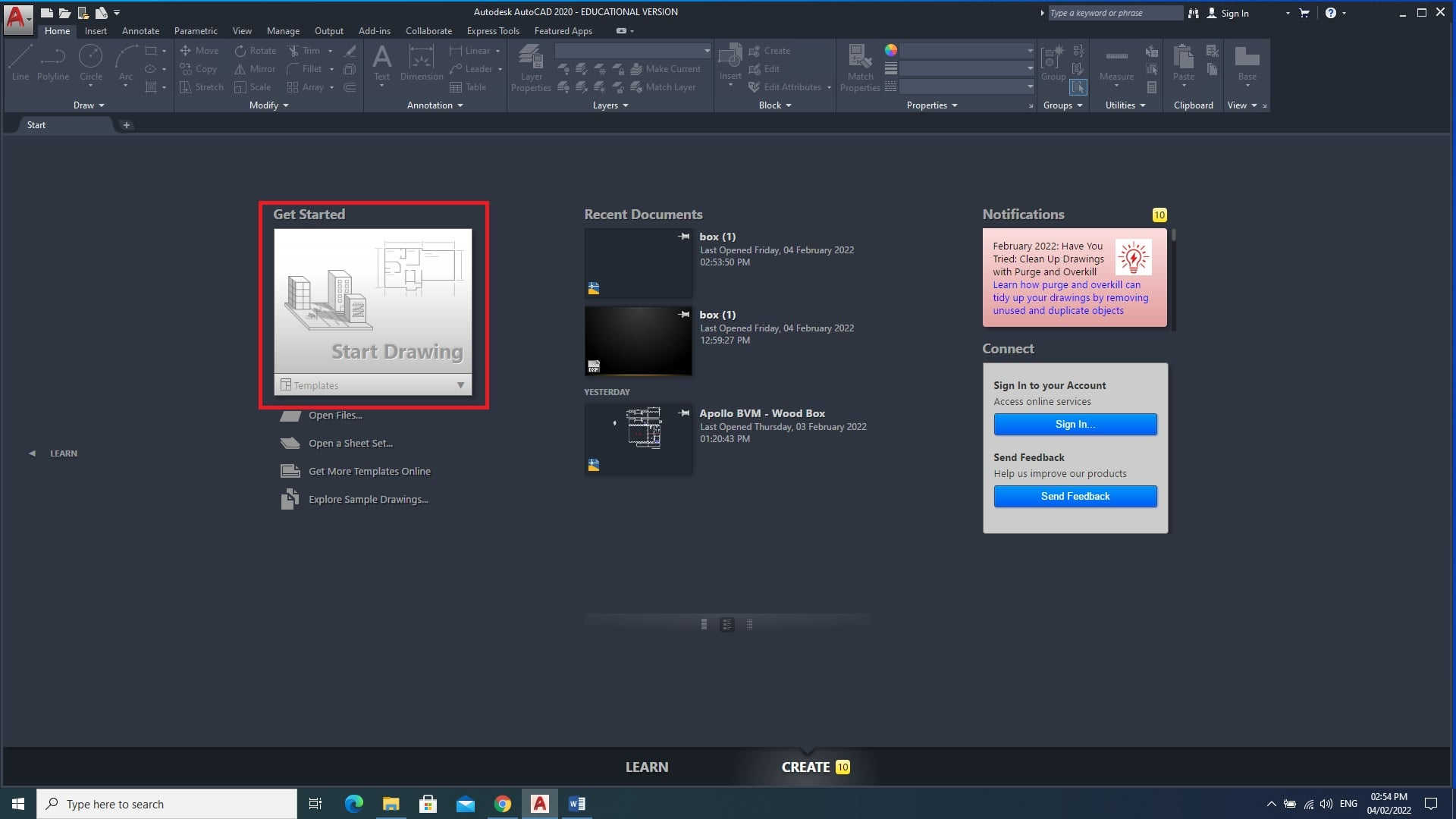
Open AutoCAD by double-clicking the AutoCAD icon on your desktop. You can create a new drawing by clicking the start drawing icon on the first page of the AutoCAD software.
Setting drawing limits
The Limits command in AutoCAD is used to set an invisible rectangular boundary in the drawing area. It limits the grid display and the point locations. We are required to specify the coordinates of the opposite corners of the rectangular window. In the command line type “limits” then click enter. The command line will ask to specify lower limits, which should be showing “0,0” click enter.
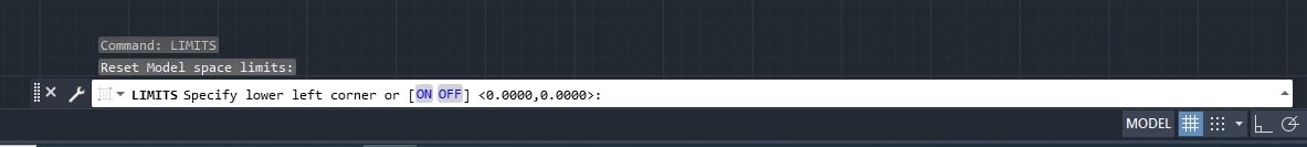
Secondly, the command line should prompt you to specify upper right corner limits. I used “100, 100” and click enter.
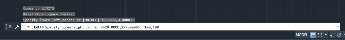
Your drawing limits should now be set.
Setting Units
The Units are used to represent the dimensions in AutoCAD. They are categorized into length, angle, insertion scale, and lighting which can be altered according to the drawing requirements. In the command line type “units” and then click enter.
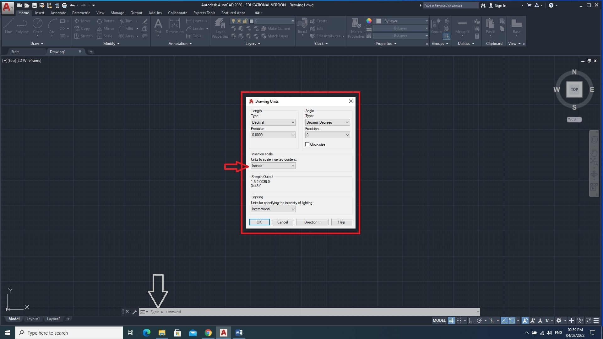
In the “Insertion Scale” tab you can change the units, which I changed to inches. You can change the precision of the length and angle if you choose.
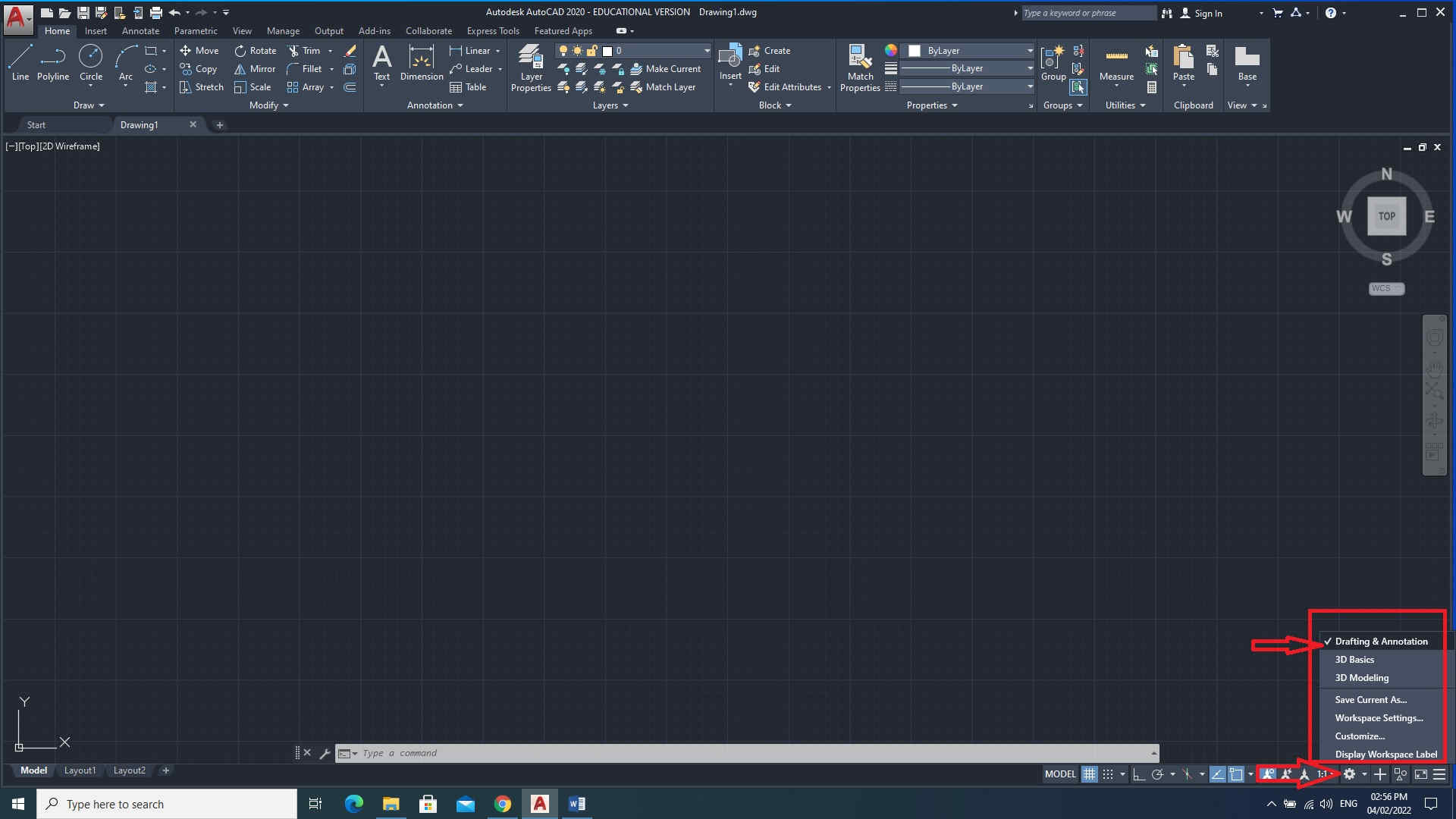
Setting your workspace
Before starting to draw, you should set up your own working environment or AutoCAD workspace depending on the type of drawing. My working environment was set to drafting and annotation.
Design Enclosure
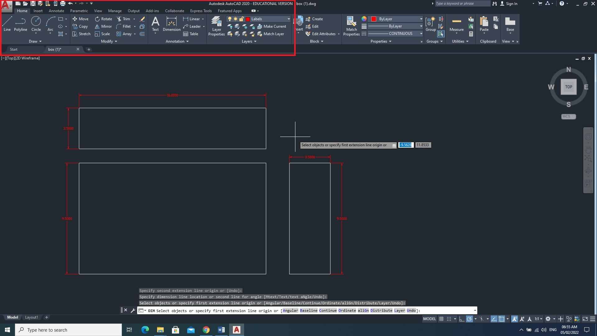
After setup, I used the 2D drawing editing tool to design my enclosure.
        •   I started by creating three rectanglar sizes as shown in image
             below

        •   I also created layers, using the "Layers" tool bar for the
             drawing (white) and dimension (red)
The rectangles were modified with fingers to create drawing below
Note:
        •    Additional pieces were included to create a chamber to house
              electronic components

        •   For building the wooden enclosure, two pieces in each would be
             cut except for the largest one

3D Design
Setting up the drawing
Open AutoCAD by double-clicking the AutoCAD icon on your desktop. You can create a new drawing by clicking the start drawing icon on the first page of the AutoCAD software.
Setting your workspace
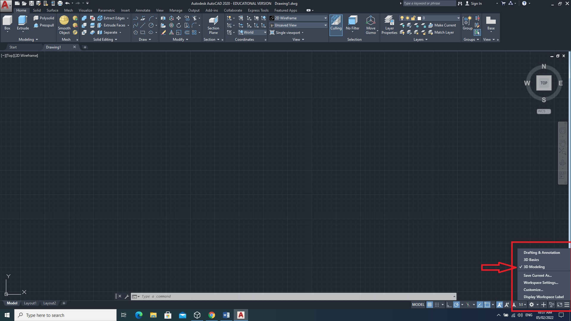
Before starting to draw, you should set up your own working environment or AutoCAD workspace depending on the type of drawing. I set my to 3D Modeling.
Designing a compression bumper in 3D
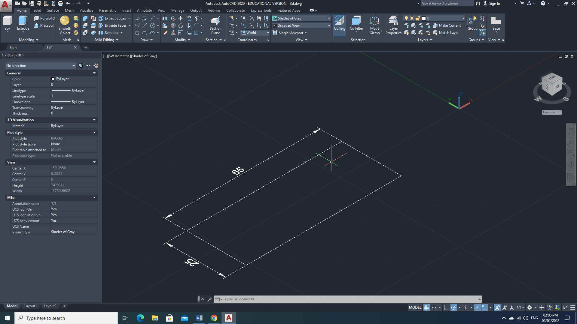
I started with drawing a 2D rectangle 25mm x 65mm
Note : I forgot to add a dimension layer (see 2D layer instruction) but did do it for the next step.
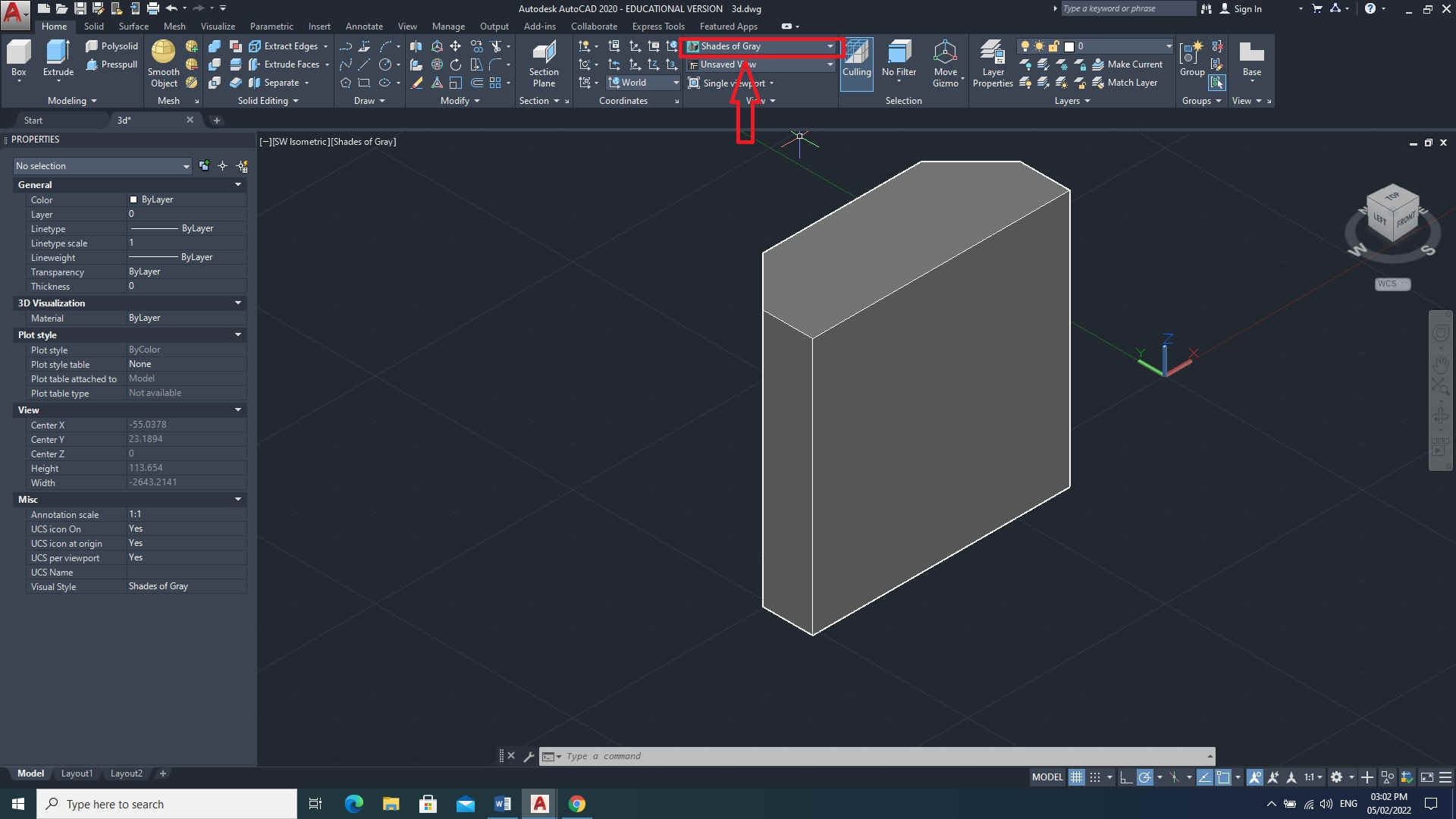
The rectangle was edited into the shape shown below. Image contains lengths and relevant angles.

I used the pushpull feature in the modelling tab to add the third dimension (z axis) at a height of 65mm.

The view was changed from a ‘2D wireframe’ to ‘Shapes and Gray’ from the view tab as shown in image below.
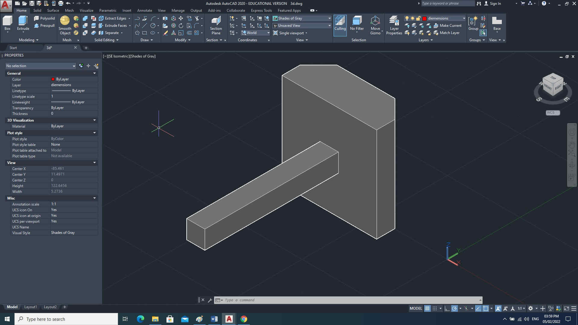
Creating a connecting shaft (later on this would be converted to a rack and pinion gear)
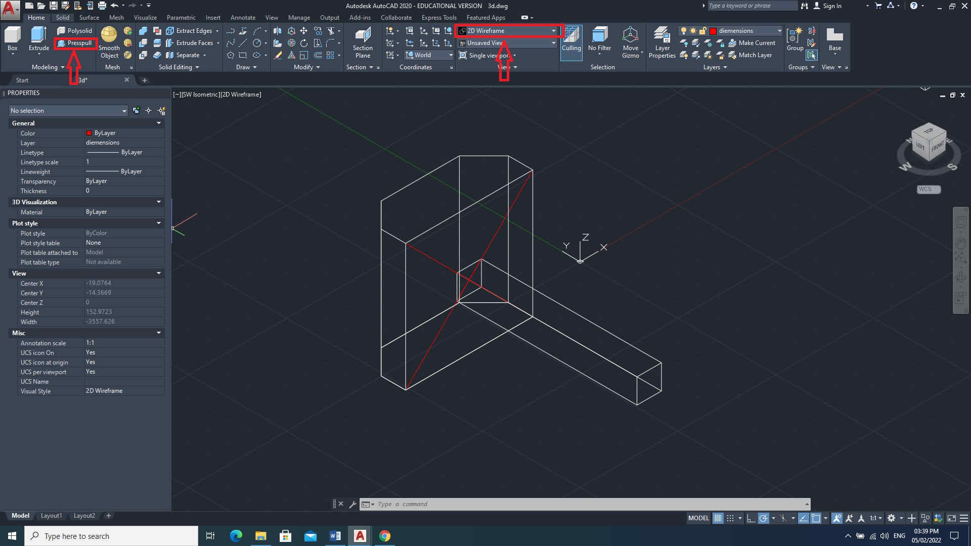
Draw a 2D rectangle 12.5mm x 92mm and then use the pushpull feature in the modeling tab to add the third dimension (z axis) at a height of 12.5mm .
Note: there are many different methods to achieve the same results; Eg. Using the Box feature in the modeling tab or instead of using pushpull, Extrude can be used in the same modeling tab.

Connecting the shaft to the centre of the compression bumper
Because the back of the compression bumper is a square, I simply connected two lines diagonally across from opposite corners. Then did the same for the shaft on the side that I am connecting to the back of the bumper. After which, I joined both components together by using union feature in the solid editing tab
Note: View was changed from shape and gray to 2D wireframe
This week I worked on defining my final project idea and getting use to the documentation process.