Final Project
Automated bag valve mask ventilation unit
My idea for the final project is to build a programmable device that is able to squeeze a bag valve mask.

These masks are typically carried by medical personnel to help get air into the lungs of persons having difficulty breathing on their own. But the masks are difficult to squeeze by hand for more than a few minutes at a time.
The immediate idea is a device that works well enough to keep noncritical COVID-19 patients stable and frees up larger ventilators for more critical patients using really fablab machines
Final Project Slide

Final Project Video
2D and 3D Modeling
PCB Design and Production
To achieve this part it is important to know:
-
I used Autocad fusion (fab academy licence)for designing
-
I used a special fab library in fusion
-
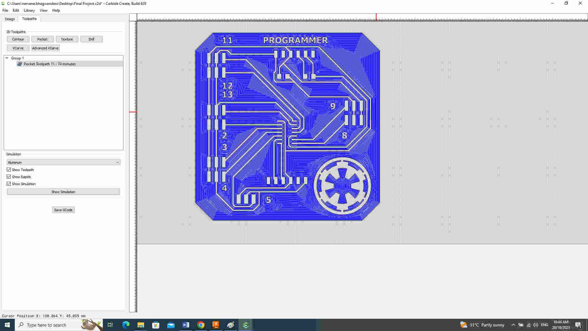
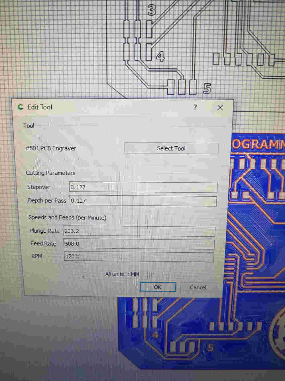
To prepare files for milling. I used Carbide Create
-
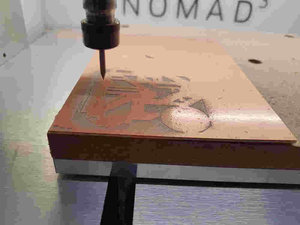
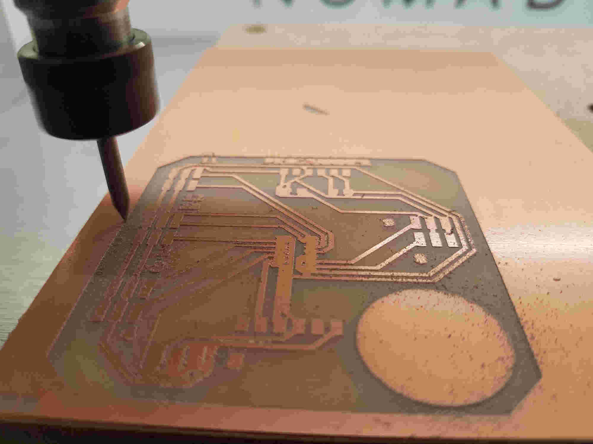
For milling I used Carbide motion software to setup machine and a Nomad 3 for milling
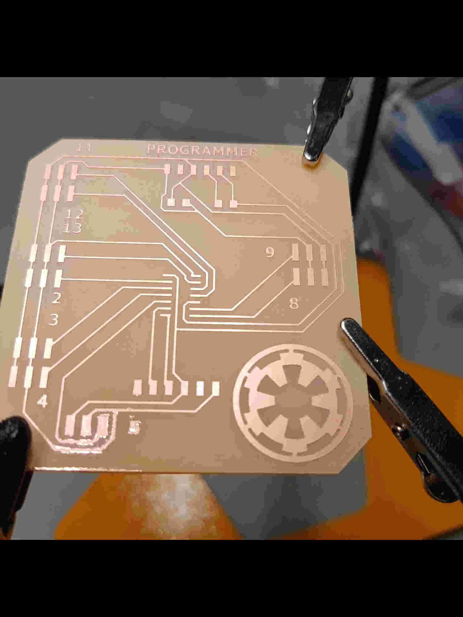
Initially I had plan on using the PCB board process in Output but I couldn’t because I had get more inputs/outputs. So had to upgrade from the Attiny 412 to Attiny 1614 chip and create a whole new board around it.
Electronic Design
I created a electronic schematic using Attiny 1614 and utilizing all the pins the get the most out of the chip. I included the UPDI into the design to eliminate the use of an external UDPI.


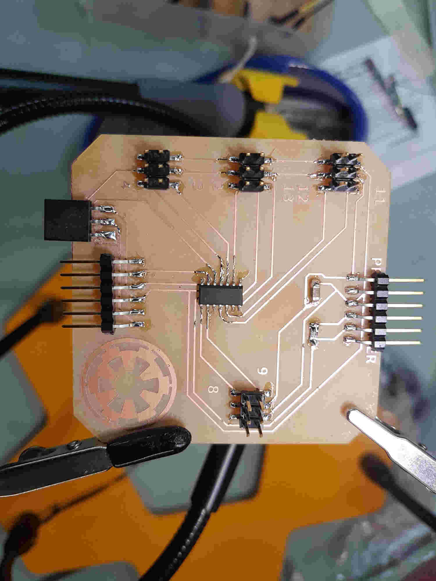
Electronic Production

Frame (body)
To achieve this part it is important to know:
-
I used Autocad fusion (fab academy licence)for designing the body.
-
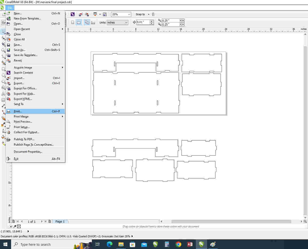
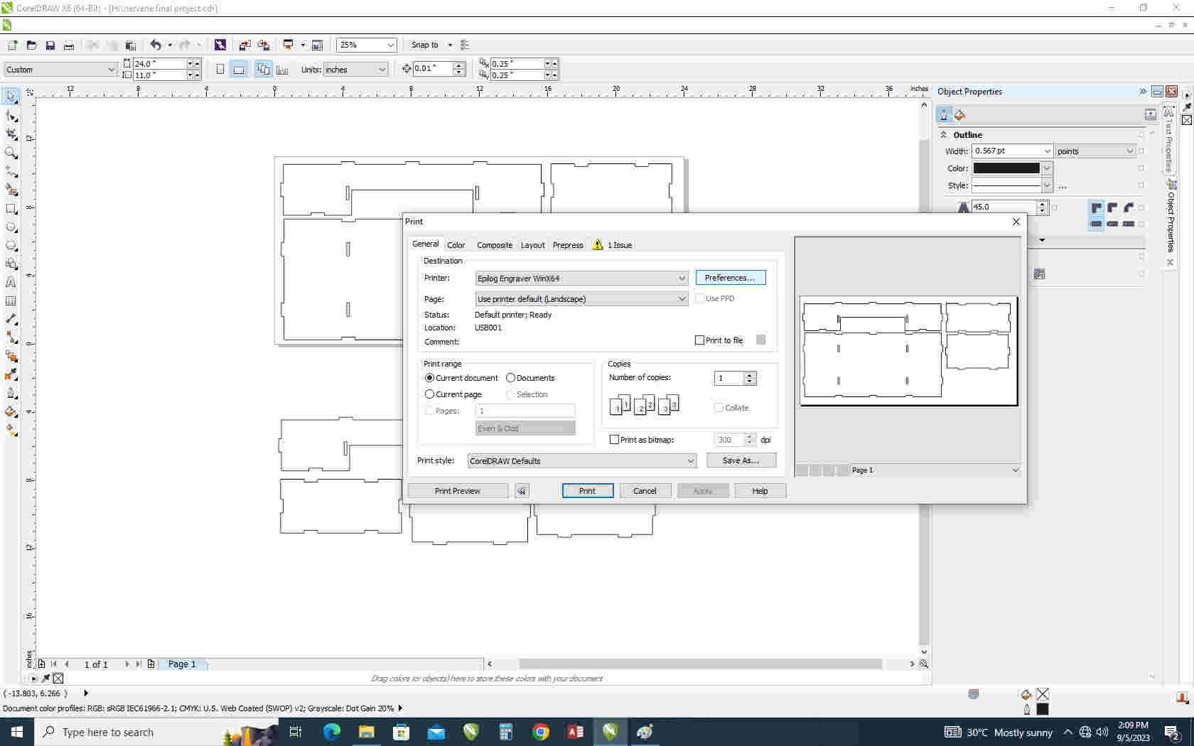
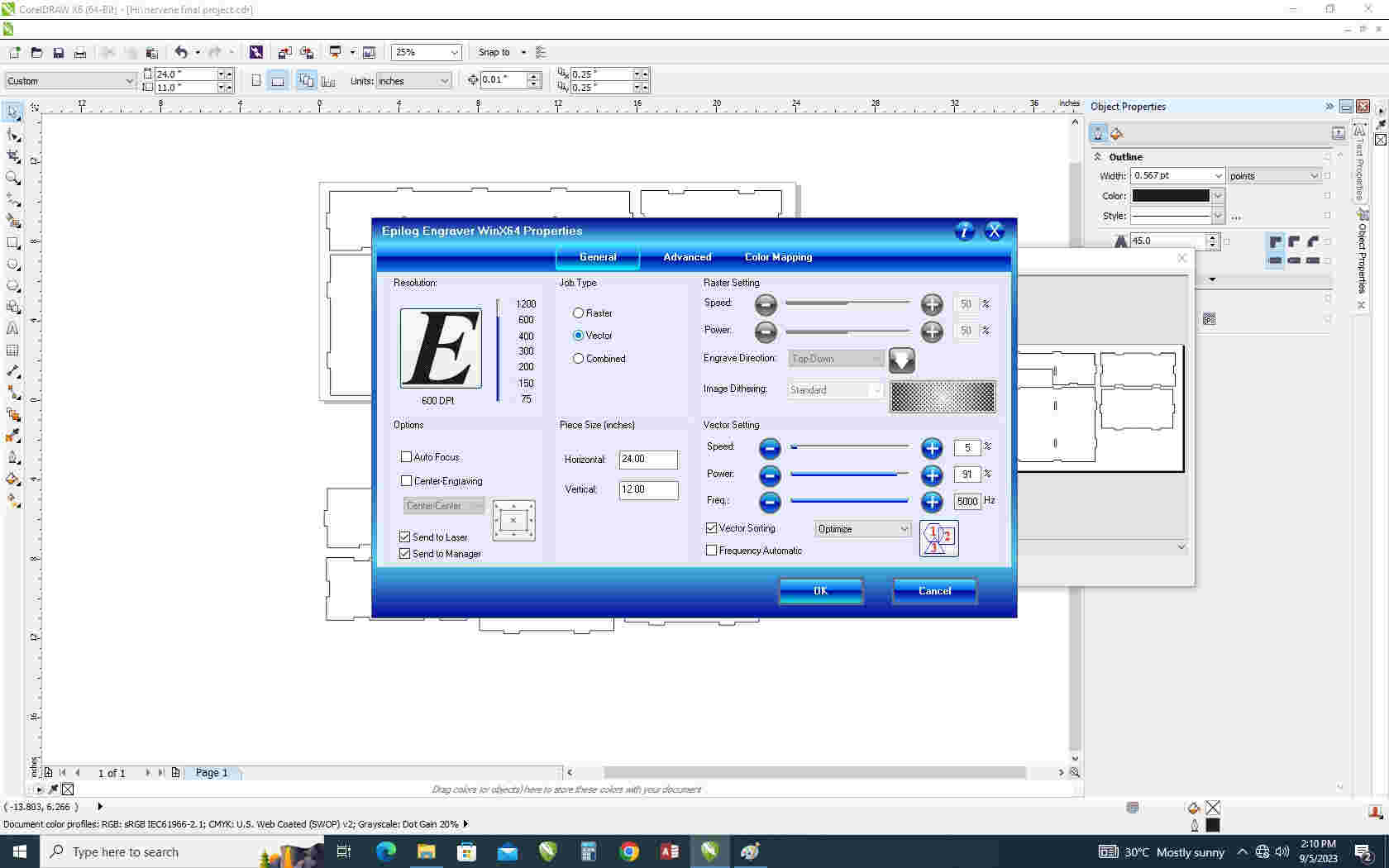
Corel Draw software to setup machine and epliog laser cutter
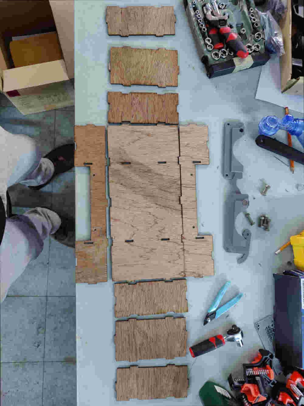
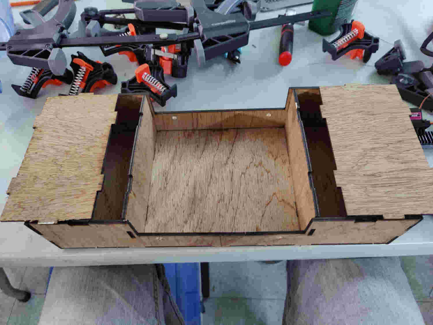
The Frame(body) was design in Autocad Fusion and was cut out from 1/8 ply wood in a laser cutter > a total of 2 1feet x 2feet was required for the body.


Files was downloaded and saved as dxf to be open in Corel Draw and sent to be cut out in the laser cutter

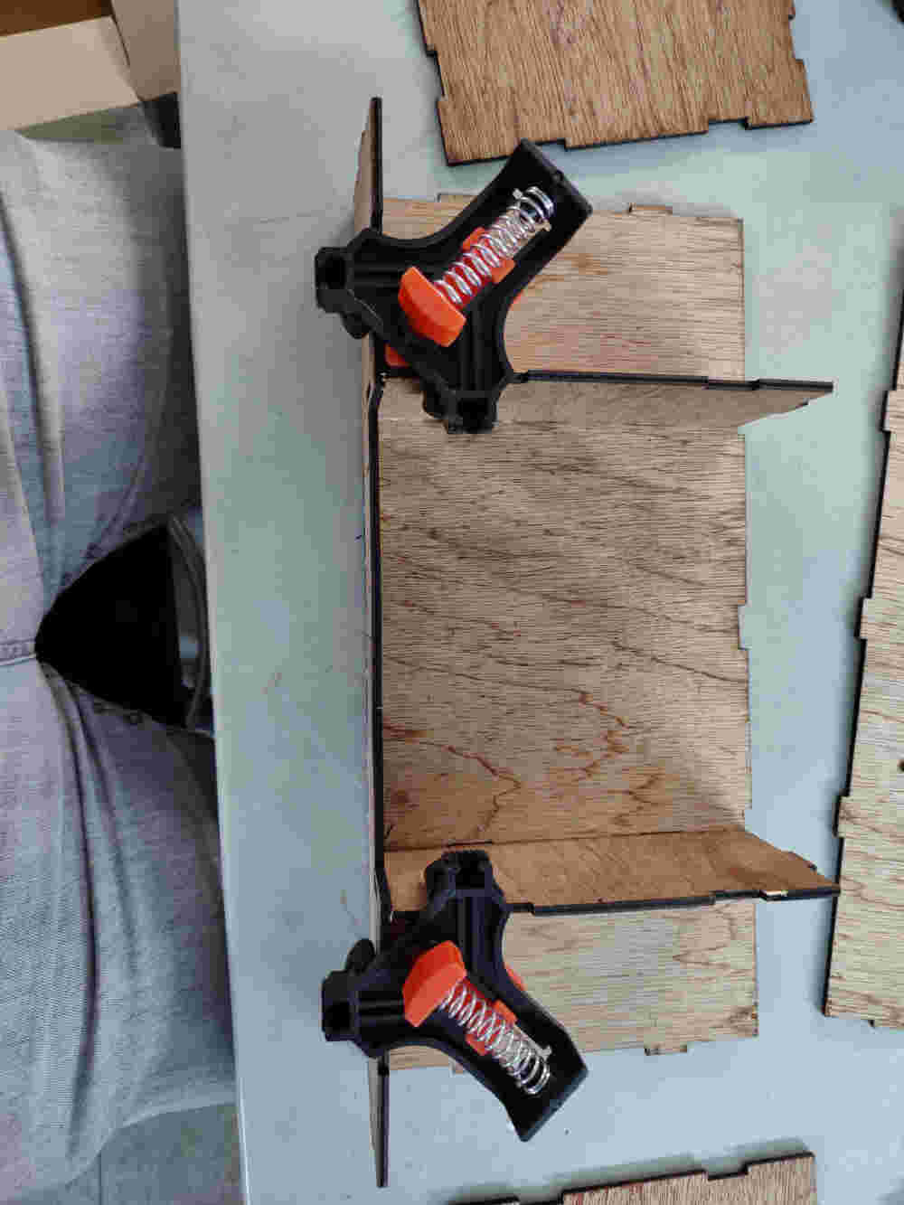
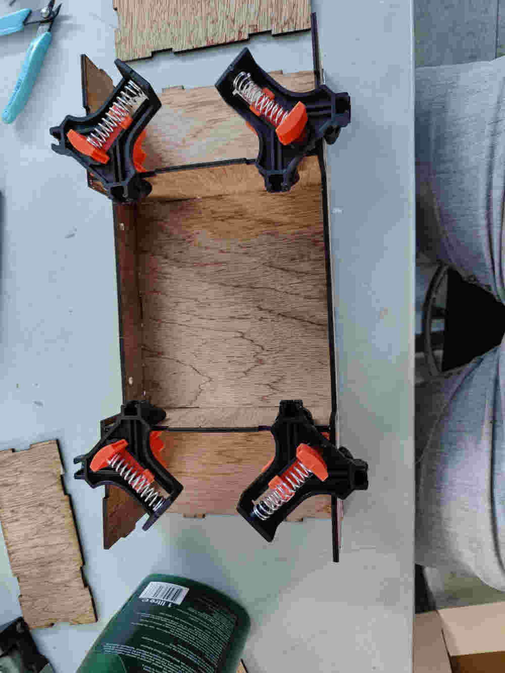
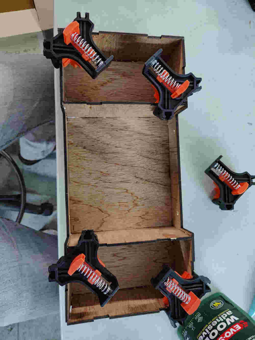
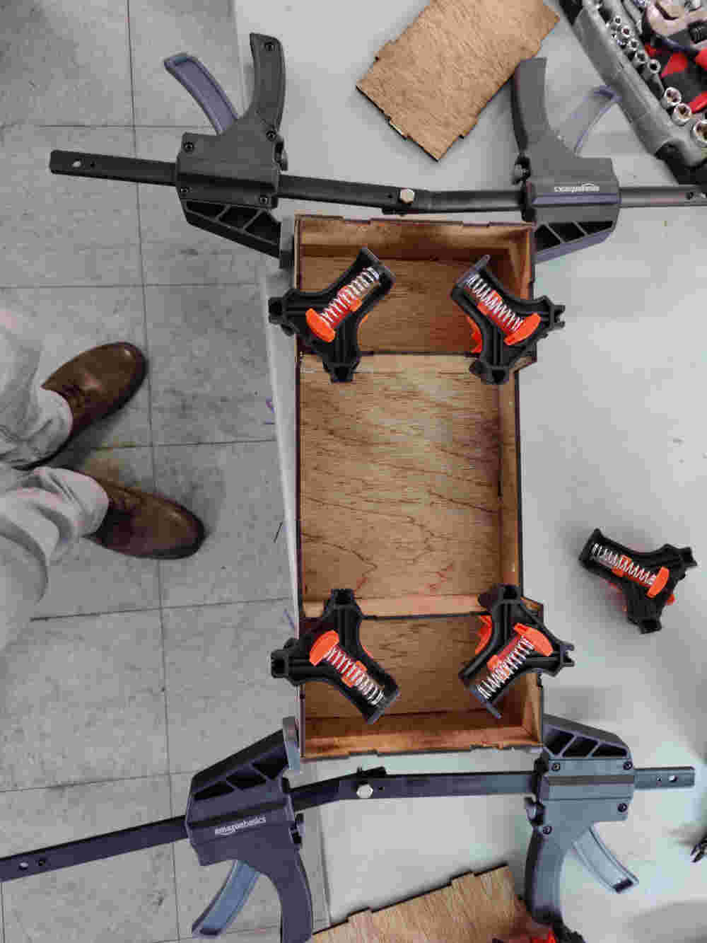
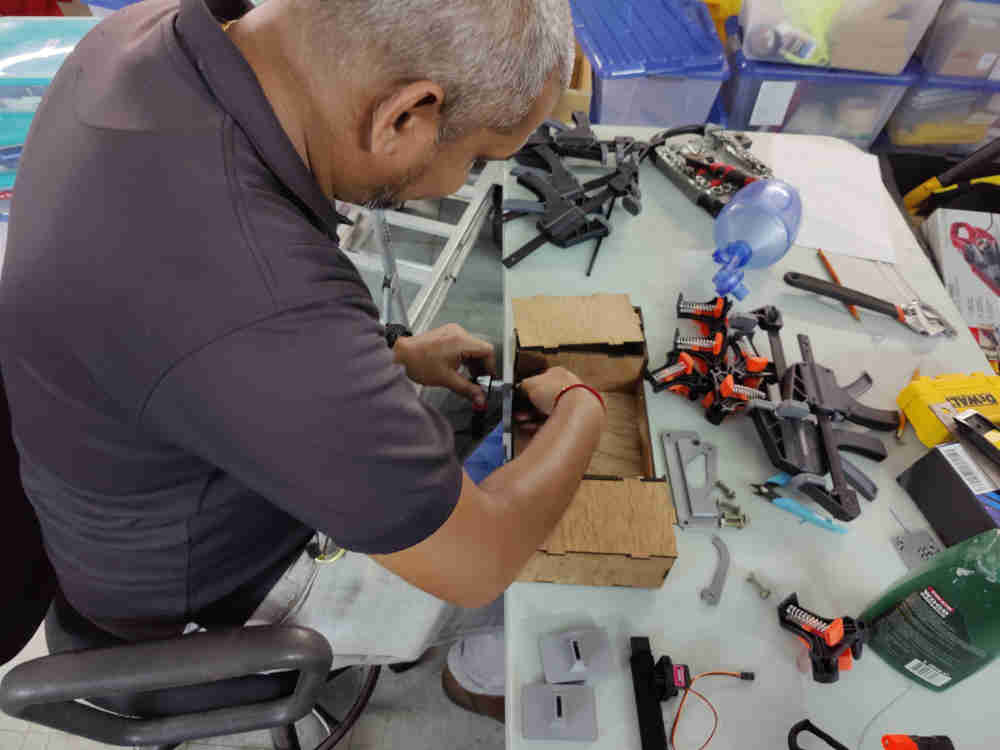
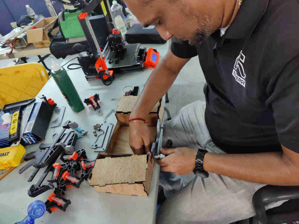
Assembly
After required pieces were cut they were assembly using clamps and wood glue.

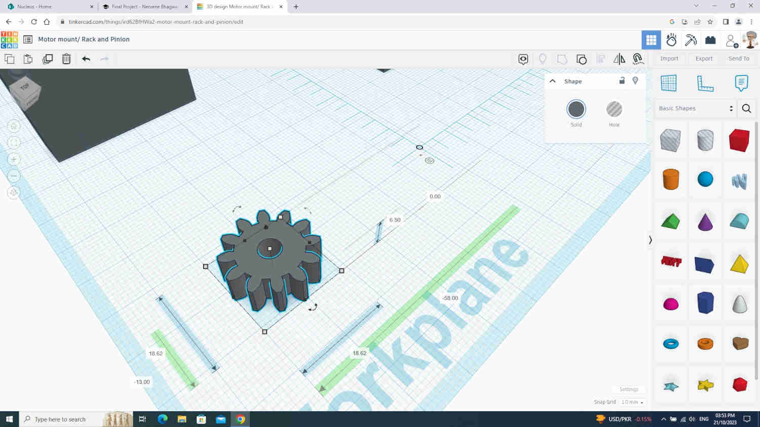
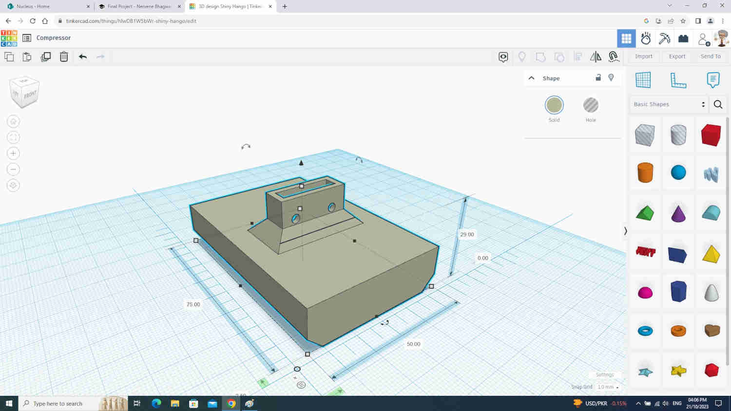
Compression Assembly
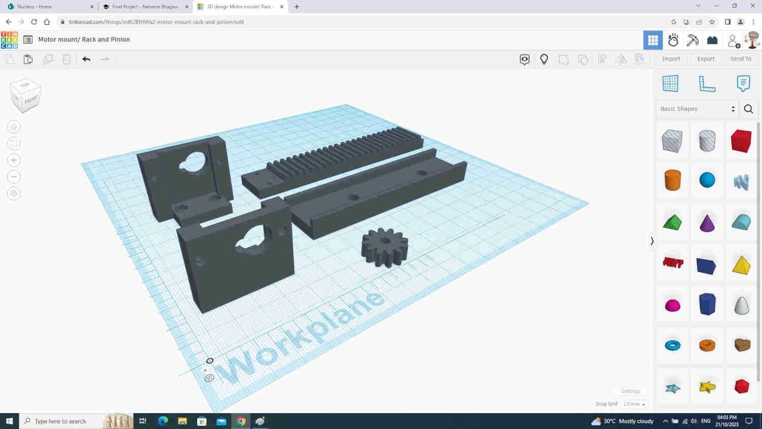
The Compression assembly is made up of the
-
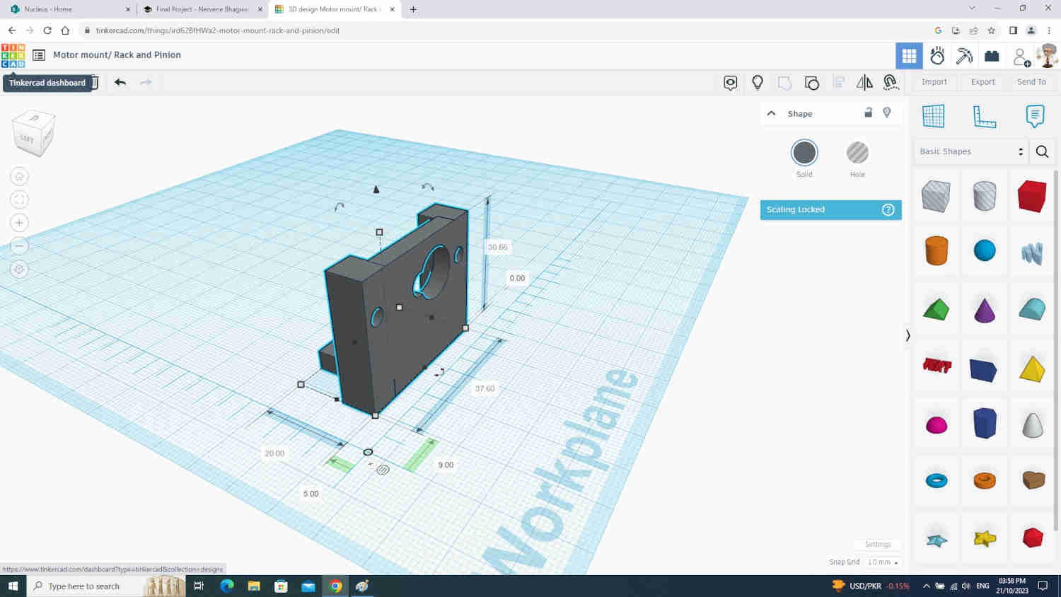
2x Motor mounts
-
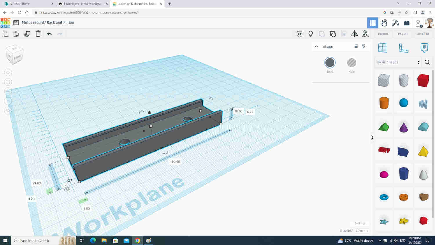
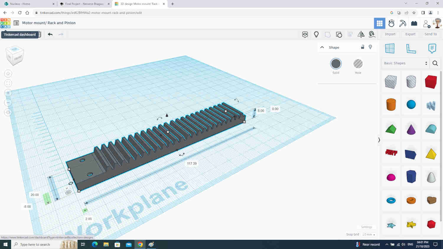
2x Rack and Pinion Gear
To design these components it was easier to TinkerCad. It is a free easy to use online 3d design software

Clamp and Arm
This was required to hold the bag valve mask in place durning the compression process
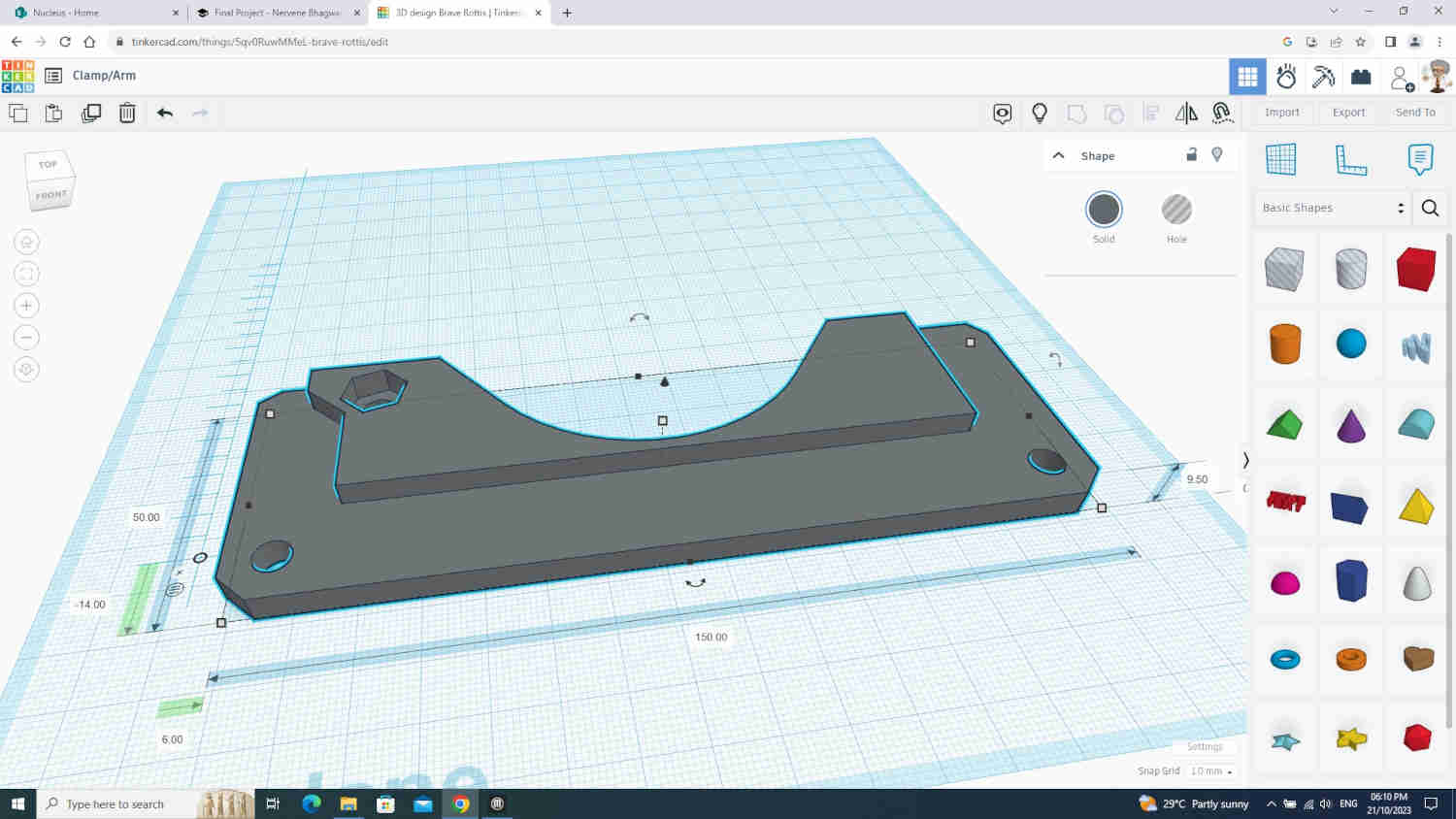
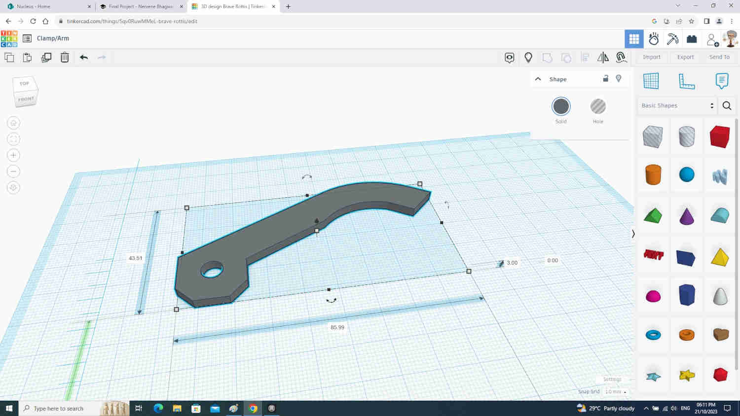
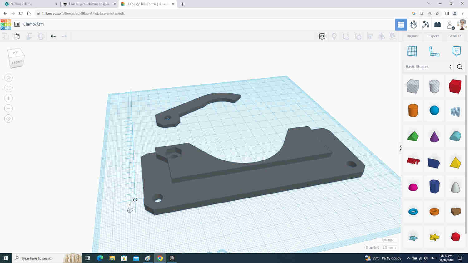

Note: The compressor and clamp & arm was design by Rice Unversity Apollo project
3D Printing
Software
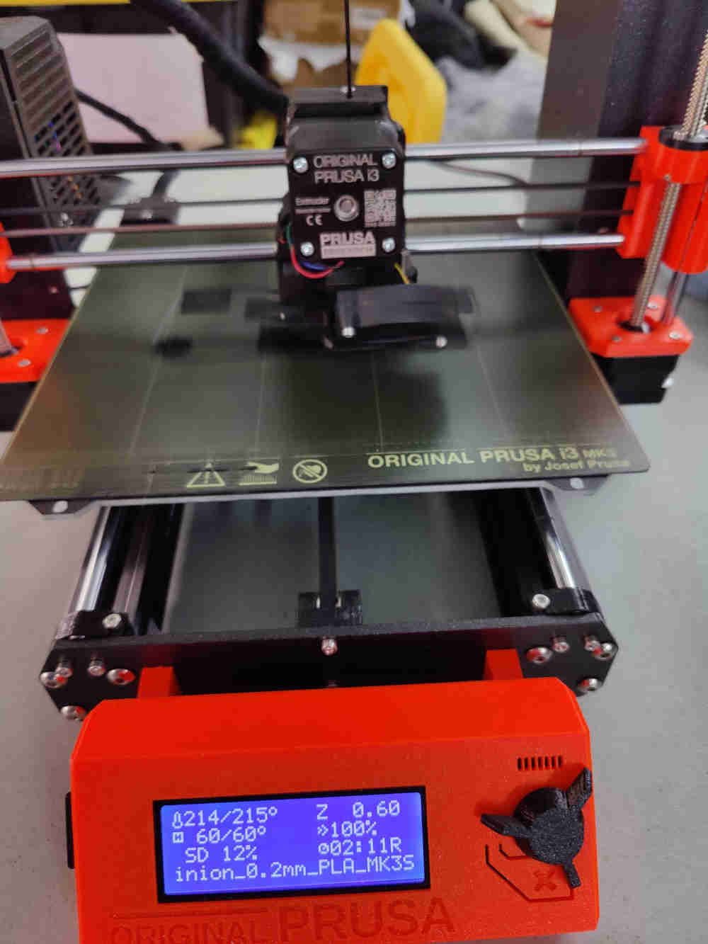
I imported all STL files into PRUSA Slicer in their respective groups and export there G-code and save on a SD card and began printing


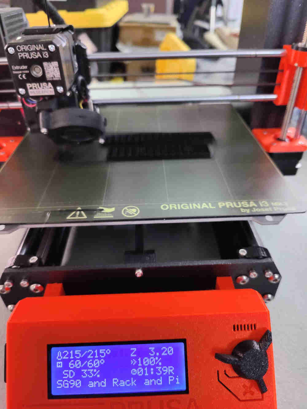
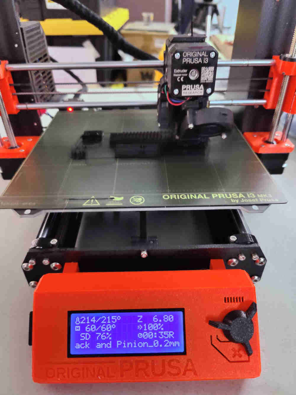
Printing Rack & Pinion gears/Motor Mount
I had to print 2 sets, one for each side.

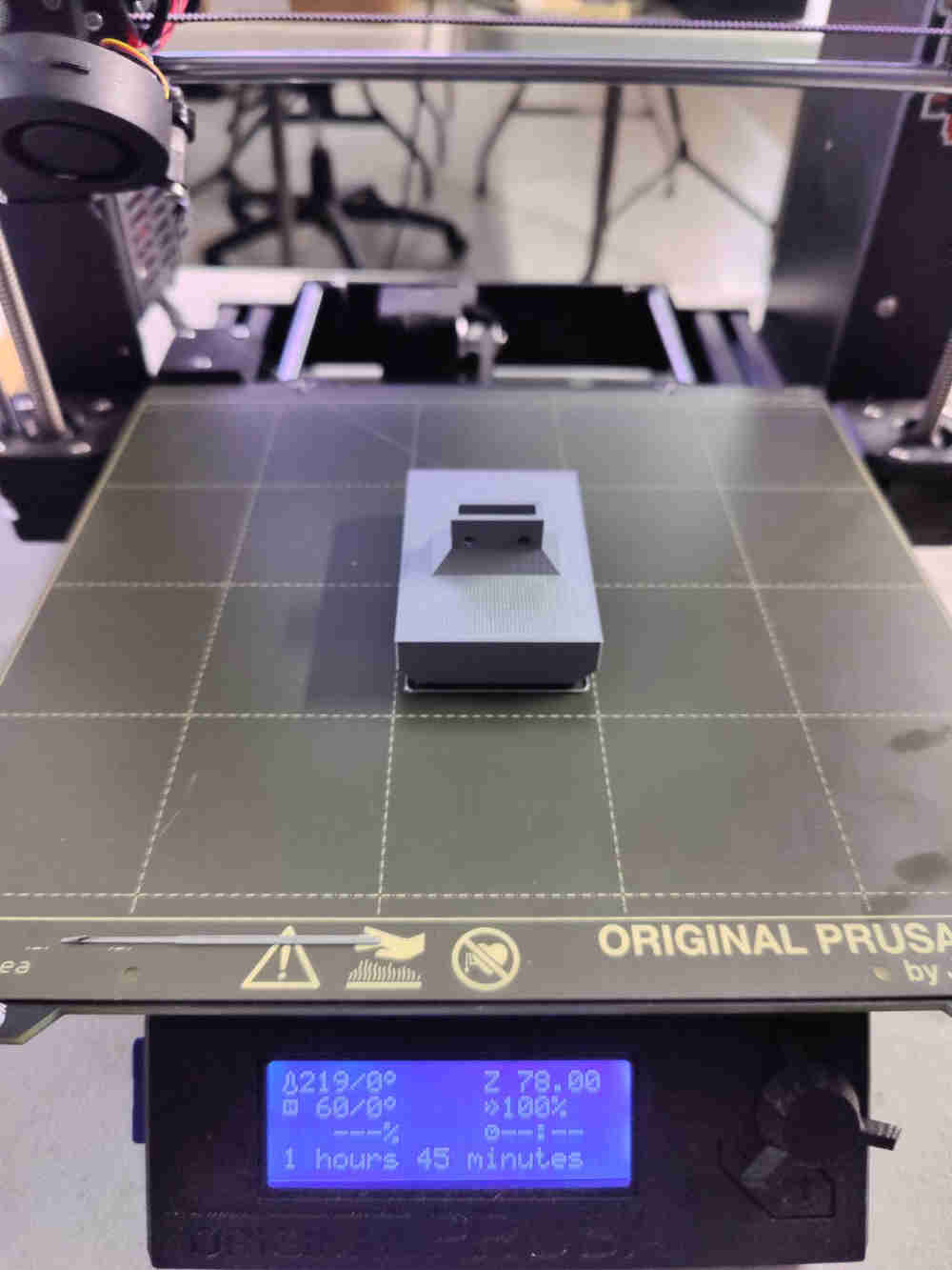
Printing Compressor
I had to print 2 sets, one for each side.

Printing Arm and clamp
I had to print 2 sets, one for each side.
Completed Prints


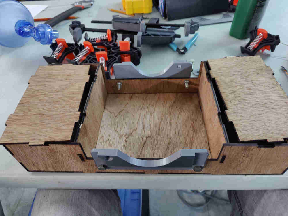
Assembly 2
Mounting Bag Value Mask Clamp
During this process I realized that I did not compensate for the holes in the frame design process for the nuts and bolts ,but it is an easy fix with a drill.

Mounting Rack & Pinion gears/Motor Mount
I mount these components using self tread screws


Mounting the Compressor/Motor


Materials
| Qty | Description | Price | Link | Notes |
|---|---|---|---|---|
| 2 | 1 x 2 1/8 ply wood | $20 TT | Ordered by sheet | |
| ½ roll | 3d Filament | $11.50 US | Matterhackers | Order 1roll |
| 1 | Single side copper laminate PCB Board 7cm x 10cm | $0.45 US | Amazon | Purchase a 10 pc pack |
| 4 | 2x3P 2.54mm pin Header Plug-in | $0.72 US | Digikey | Ordered many |
| 1 | 1 x 3p 2.54mm pin header | $0.26 US | Digikey | A rail cost $3.45 US |
| 1 | Attiny 1614 | $0.90 US | Digikey | Ordered many |
| 1 | 1 uF Capacitor | $0.05 US | Digikey | Purchased a 100 units |
| 2 | Conn 6 FTDI smd header | $0.54 US | Digikey | A rail cost $3.45 US |
| 1 | 4.99 k ohm Resistor | $0.03 US | Digikey | Ordered many |
| 1 | 3 pos female pin header 2.54mm | $0.65 US | Digikey | Ordered many |
| 1 | Ardunio servo sg90 | $4.00 US | Amazon | Purchase a 10 pack |
| 1 | Bag value mask | $30.00 US | Amazon | |
| Wood glue | Had in stock | |||
| Varity of self-tread screws | Recycle screws from old electronic equipment etc |
Programming
Now programming is the most frustrating part off this project for me and programming is not one of my strong suits. I did get some assistance from one off my colleague’s .
To achieve this part it is important to know you would require:
-
Ardunio software
-
Your PCD board
-
FTDI cable
-
Servos
-
Led
-
button
I connect the outputs & inputs and note their pin position
-
servo 1 = PA 5
-
servo 2 = PA 6
-
button = PA 1
-
LED = PA 2
And putting together code from output week and embedded week assignments. After hours and two days this is what I got !
#include <Servo.h>
#include <avr/io.h>

#define delaytime 5 // delay time between steps (ms)
#define servopin0 2  // servo 0 pin (PA6)
#define servopin1 1 // servo 1 pin (PA5)
#define BUTTON PIN_PA1
#define LED   PIN_PA2


Servo servo0,servo1; //declare servos
int angle = 0;
byte lastButtonState;
byte ledState = LOW;
byte buttonState = LOW;
byte onoffstate = LOW;

void setup() {
   servo0.attach(servopin0); // attach servos to pins
   servo1.attach(servopin1);
   pinMode(BUTTON, INPUT);
   pinMode(LED, OUTPUT);
   lastButtonState = digitalRead(BUTTON);
  }


void loop() {
      buttonState = digitalRead(BUTTON);
      if (buttonState == HIGH) {
        lastButtonState = buttonState ;
        onoffstate = !onoffstate ;
      }
      if (onoffstate == HIGH) {
        digitalWrite(LED, HIGH); // turn on LED after button is pressed
        servo0.write(0);
        servo1.write(180);
        delay(1500);
        servo0.write(180);
        servo1.write(0);
        delay(1500);
      }
      if (onoffstate == LOW) {
        digitalWrite(LED, LOW);
        delay(1500);
      }


   }

SUCCESS kinda lol
Packaging
I secured the PCB board to the wooden frame(body) using velcro and connected all the outputs & inputs.

Close up shop

Conneted ftdi cable to run system
