Electronics design
For this week assignment we had to :
- Link to the group assignment
- Documented what you have learned in electronic design
- Explained problems and how you fixed them, if you make a board, and it doesn’t work; fix the board (with jumper wires etc.) until it does work.
- Included original design files (Eagle, KiCad, etc.)
- Included a ‘hero shot’ of your board
- Loaded a program and tested if your board works
Personal assignment
Design
I started this week assignment a few hours ago… I decided to mill a pretty simple board using Eagle embedded in Fusion360. This board will just have a bunch of LED to see what color works the best. I also plan to add a button to turn them on and off.
Later, I tried to add a Serial interface to the board to test communication with it.

I began by importing every library I needed. Likewise, I first imported the fab.lbr but to my mind, some simple component are missing. I found another library from a fabacademy student online. The fab_new.lbr is much more convenient. This library provides the Attiny412 which I decided to play with. This library also provide a 3 pin connector very useful for UPDI.
I began by importing all my components into the schematic project. Then I place it trying minimizing the wiring mess. The Supply2 library from eagle cloud is very useful to simplify the power supply wiring.

I then wired everything. Except… The button, A that time I forget to wire button to the attiny… I fixed that later :()

As you can see, I didn’t have enough output to control my LED independently. I could however remove the serial or the button to change that but I didn’t notice it will be a problem while I was designing… I discovered that later while programming ! :) Then I switch to the Board designer. At the beginning, a mess… All the component were spread over the board…

I reordered everything and place them trying to minimize the PCB size and the wiring mess.

Then I use the autorouter to route everything. I use the basic design rules supplied by fabacademy. But even the autorouter is helpful, it is limited. It is good to give an idea of how the design may look, but we need to route things manually after that. The autorouter didn’t find a 100% solutions at the first time. I had to look for impossible connection and I move my components to help him find his way through the circuits.

I finally got this automatically generated result. After a few iterations I got a convenient design that I may work with. Even if the parts are all connected, The path wasn’t very elegant. I moved a few routes manually. Here is the adjusted board :


Fabrication
I was pretty ok with the design a that point. But unfortunately I didn’t check my connection… Even at 2:00 am I was sure about my work. As expected I forget to connect the button the Attiny. I can fix that by using an external wire. (I regret)
Milling
Even so, I used Mods to mill my PCB. I had to generate a PNG using Fusion/Eagle… I manage to find a process : - 1 : Hide all PCB layer except the top layer - 2 : Go to document -> print - 3 : Export a PDF with the smallest page format possible & using black/white color. - 4 : Open the PCB with Inkscape to convert it to a PNG or SVG - 5 : Open it with mods

I bought myself a sainsmart genmitsu CNC to mill PCB at home. I had to characterize the machine again. Furthermore, I set the right parameters in mods to mill the linetest again.

I use Grbl controller to control my machine

I successfully milled these traces. The V mill can be very precise when new. I use two different V mill. One for the traces, the other for the outline.
I figure out that when I use a V mill for outline, then I loose a lot of precision on the next trace cutting. Using only a bit for engraving prevent shearing too much the mill.


Another problem I got was about cutting depth. I use the supplier parameters from my PCB board. The parameters said my board was 1.5 mm thick, but it wasn’t ! It was 1.7 mm thick. As expected I didn’t go through the material…

As a result I as to finish the cutting using sand paper to reduce the thickness of the material behind the cut bottom. I finally got my PCB

After this test I imported my PCB PNG in mods. I set the right parameters using this V shaped mill calculator : Link I started the milling and wait for about 20min until the end. It successfully removes the copper down to the glass fiber.

Then I started the cutout program. Unfortunately, I’ve done a calculation mistake, and it doesn’t go deep enough… I used sand paper to get rid of the remaining material. I finally got my PCB !


Soldering
I started the soldering by placing all the component but the microcontroller and soldered them using only my iron and tin. The soldering way longer than I expected. The component are so small that they stick to my iron… Later I ordered some soldering paste and a better soldering station (hot air).

I also soldered the big flat button before the microcontroller, which is stupid since I had to space left to solder the attiny with ease…

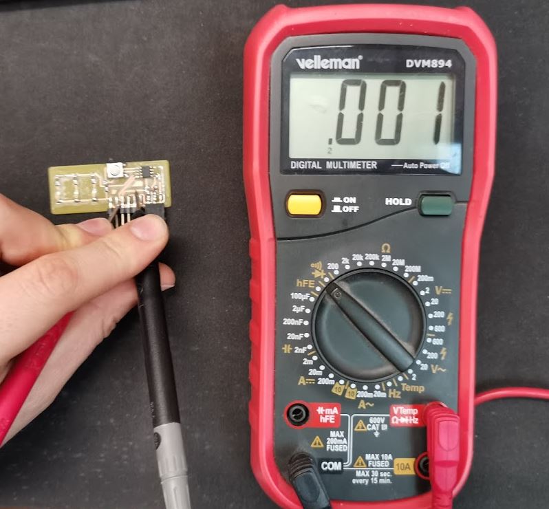
After the soldering, I checked my connection using the multimeter I have at home. I tuned the multimeter to play a beep when the current flows from one electrode to another. And tested every route on the PCB.
I found two open circuits. I needed to solder two LED again. I used another tin this time with Lead in it. Lead is poisonous so I had to open the windows, but it is way easier to solder than my lead free tin.
Programming
I used my UPDI programmer from PCB production assignment. I watched again the circuit to remind me the wiring.

In Arduino, I installed megatinycore add-on and selected Attiny 412 as my chip. I’ll use the Serial port and 4.7k PyUPDI programming methods. I connected the board and clicked Upload.

After a while, the program begin to upload into the chip. I’ve coded a simple program to make my LED blink.

Here is the result :
// the setup function runs once when you press reset or power the board
void setup() {
  // initialize digital pin LED_BUILTIN as an output.
  pinMode(2, OUTPUT);
}

// the loop function runs over and over again forever
void loop() {
  digitalWrite(2, HIGH);   // turn the LED on (HIGH is the voltage level)
  delay(1000);                       // wait for a second
  digitalWrite(2, LOW);    // turn the LED off by making the voltage LOW
  delay(1000);                       // wait for a second
}
Group assignment
Once again, I did this group assignment alone. I used two testing unit, a multimeter, and an oscilloscope.
I have to understand what type of signal a servomotor needs to be moved. I want my final project to be compatible with the servo library from arduino. I’ve built a little kit oscilloscope a few years ago. It is made out Plexiglas and I had to solder a few electronic components on it. After uploading the firmware I used it to measure vibration using piezoelectric crystals. It worked very well.

But today we need to see what servo receive. I get the following code to run into an Arduino Mega and connected the oscilloscope to the servo PWM signal Output.
#include <Servo.h>

Servo myservo;

void setup() {
  myservo.attach(9);
}

void loop() {
  myservo.write(0);
  delay(4000);
  myservo.write(90);
  delay(4000);
}
Servomotor should receive on/off signal with a very precise timing. Most microcontroller have PWM outputs. PWM means Pulse Width modulation. This protocol is sending pulse at a precise frequency. Those pulses can vary in duration.

The servo are controlled using this principle where each pulse width is associated with an angular position. This is an efficient way to control something precisely without sending lots of data using a communication protocol. Instead, the trick is to use the ability of microcontroller to measure time precisely to transmit data using time has unit.

As you can see, we can clearly see the pulses on the screen. It seems to be a 50Hz frequency, which is quite common for PWM servo control signal. Now We want to check if the signal match the theoretical timing seen above. My pulses should, according to my program, alternate between 1ms pulse and 1.5ms pulses Let’s check that !

It seems the signal is effectively alternating between two pulse length both at a 50Hz frequency. I tuned the oscilloscope settings to zoom on the pulse and make them match the 0 on time axis in order to measure correctly the pulse width.

As you may see, the subdivisions are equivalent to 0.2ms. So this signal above show pulses that are 0.58ms wide.

This second signal shows pulses of 1.58ms. If we ignore the mounting slope and start counting from the 5v peak. Signals are respectively 0.5ms wide and 1.5ms wide.
This doesn’t exactly match the theoretical values. But it seems still coherent.