Mechanical design / Machine design
For Machine week I’ve worked on two different project in two different labs. In 2021 I’ve work on the wire bending machine with Sylvain. In 2022 I’ve work on a Bidepal strange robot named BILLE.
Wire bending machine
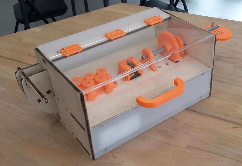
In 2021 Sylvain, Fabien and I worked on a wire bending machine, to know more about the project, click on the button below :
In short, our project is inspired by this one :
Dispatch of tasks
On this assignment, we are three students
- Sylvain will to the Cad design on Fusion 360 (helped by others),
- Fabien will work on the machine casing and integration,
- I’m in charge of the programming (Machine control & simulation).
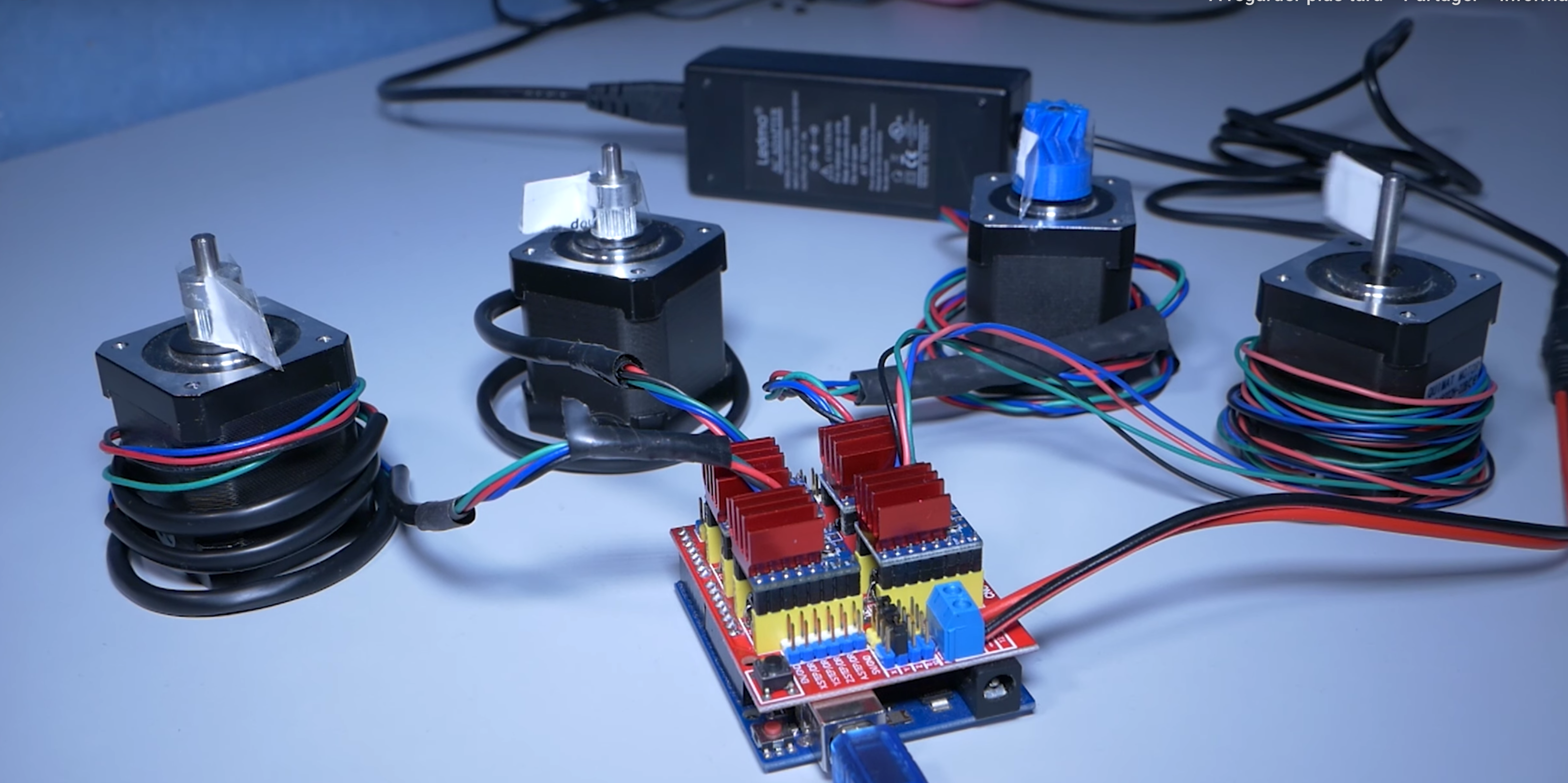
After defining the project I begin to collect some salvage to create the motorization and the electronics. Fortunately I found an old arduino with a cnc shield. I also grabbed a few stepper motors (Nema 17) on an old 3D printer.
My contribution
My role was to help Sylvain with the fabrication and to create both the simulation and the program of our bending machine.
I started creating a simulation using processing. Processing is a Java based graphics programming environment. It is very useful to show stuff on the screen without spending too much time setting up a graphics library.
Here is an overview of what I created :
The program is divided into 6 tabs (files). : - Main : Containing the main loop and the setup function - Bend : Which is dedicated to the machine control - GUI : Which is dedicated to the user interface - Mouse : Which is dedicated to mouse control - Shaft : Which is dedicated to the gray shaft simulation and control.
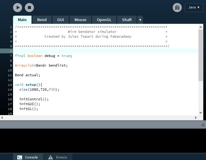
This program allows the user to design shape and then send the program to the bending machine. Each instruction is translated into code which is then interpreted by the program in the Arduino.
Download
Here are the files of the project :
BILLE the Bipedal lattice locomotion robot
I few months ago, I discovered a project at the MIT CBA lab named BILL-E. I watched the video from Adam Savage’s Tested where he visits the MIT CBA Lab with Professor Neil Gershenfeld.
Neil and his student Ben Jenett presents the project, and I was amazed how brilliant it is. The whole Idea is to reduce the payload of planes or spaceships while bringing construction material from point A to point B. This make lots of sense for spatial exploration for instance. Imagine you want to build a house on Mars. Or even a bridge. You can either use the local facilities and resources or you can bring your stuff with you. For the first explorer to travel, they cannot use any local facilities, so they need to survive and craft, shelters, bridge, wall whatever, from scratch.
The genius of the project is to use very lightweight material such as carbon. It is relatively easy to produce carbon fiber bars nowadays; Bars are pretty compact and also very light. If you arrange bars in octahedron latice structure.

But the project goes beyond the mechanical intelligence of arranging bars into complex and stiff structure. The team also created a robot capable of moving on and into the lattice. The robot may be able to reconfigure the lattice by himself to transform a shape. Robots can collaborate to speed up the process.
I’ve already seen this concept in a Sci-fi book. But what I really like is the fact that the robot has a very few sensors. I get its precision from the lattice and the advantageous shape of octahedron.
Lattice Design
This is why I wanted to give him a try. One of the most common problems in robotics is the location. Robot need to know where they are to perform. As our macroscopic space is mostly continuous, robots need to have positioning systems such as Lidar, GPS, contact switch and so on… But using a lattice, the robot don’t need that ! If the robot move from one shape to another, He knows exactly by how much he should move has the space is discretized into smaller units.
I decided to make y own BILL-E robot. As there is two part of the project, I began by working on the lattice.
I need to create an octahedron from bars and joint. I looked for lightweight bar that are accessible. It turns out I have lots of FDM spools. I tried to cut PETG filament into small bars to build my first octahedron using sticky paste as joint.
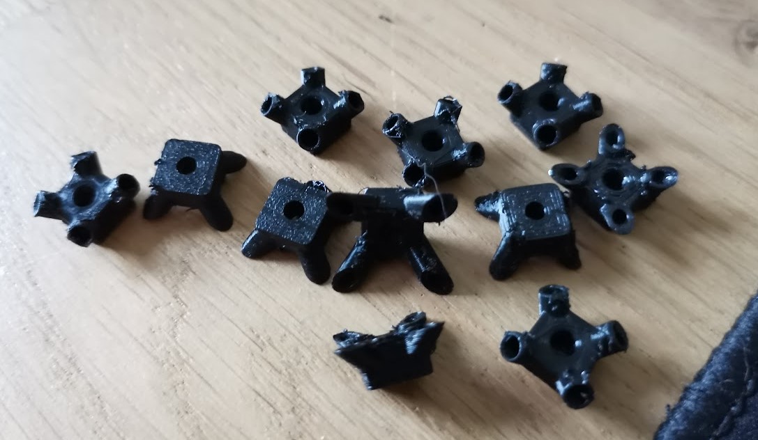
Later, I designed this little joint into Fusion 360 :
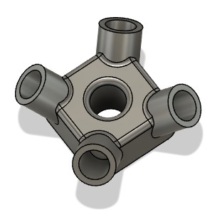
The 4 symmetric holes are 1.9 mm wide just enough to press-fit 1.75 filament from my ender 3. It turns out those holes where too small after 3D printing them, The FDM process
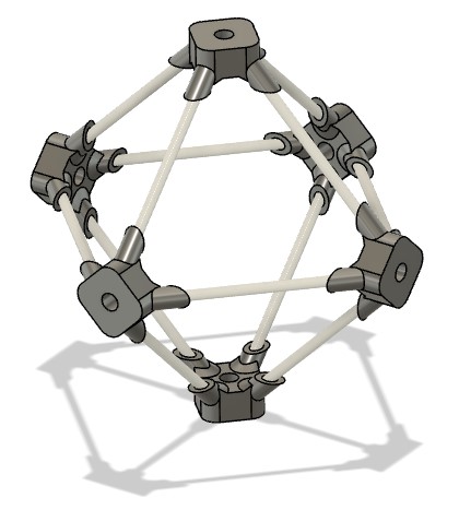
Then I created a cylinder the size of a piece of FDM Filament. Then I assembled all the 6 joints together. It was really easy in Fusion360 since the assembly tool does a lot automatically. I simply selected the center of contact face on the filament and the joint.
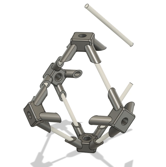
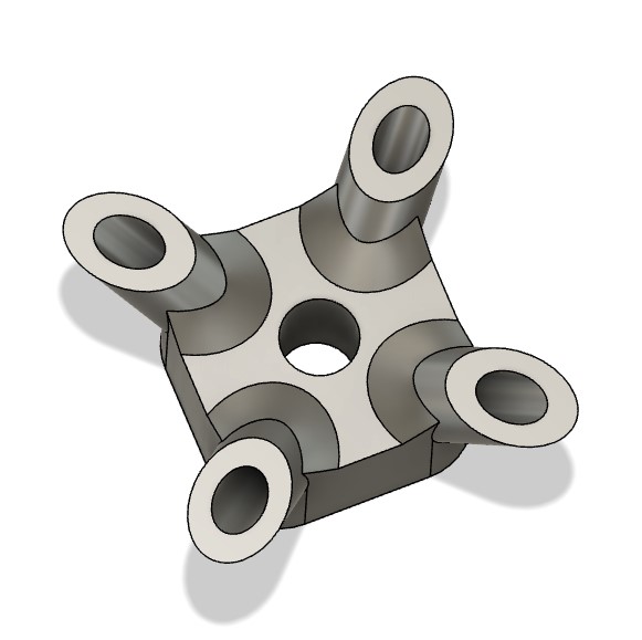
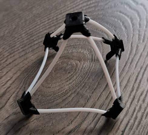
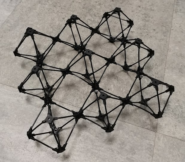
After a while repeating this process I finally created an octahedron.
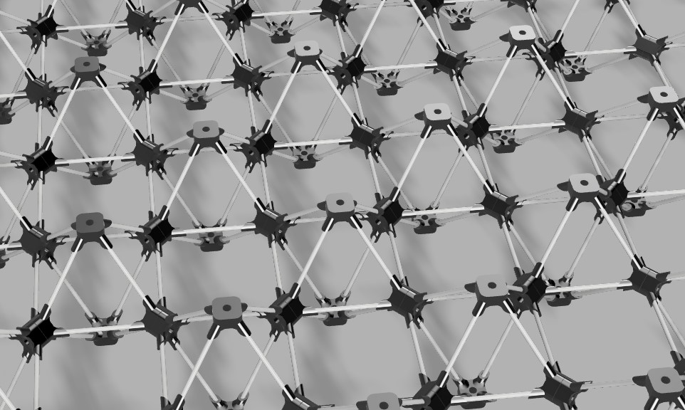
When we need a full lattice, so I began to assemble lots of them. Here is how it looks like in render mode :
I 3D printed lots of joint. While the printer was running, I was cutting piece of filament equal in size. I’ve done a little trick to automate the production of those joint. I created a routine were the machine go up, backward and go down to the buildplate. Then it go straight into the piece to push it to a litle storage box.
Here is the GCode I used between part:
G1 Z30
G1 X120 Y200
G1 Z1
G1 Y0
G28 X Y Z
BILL-E Design
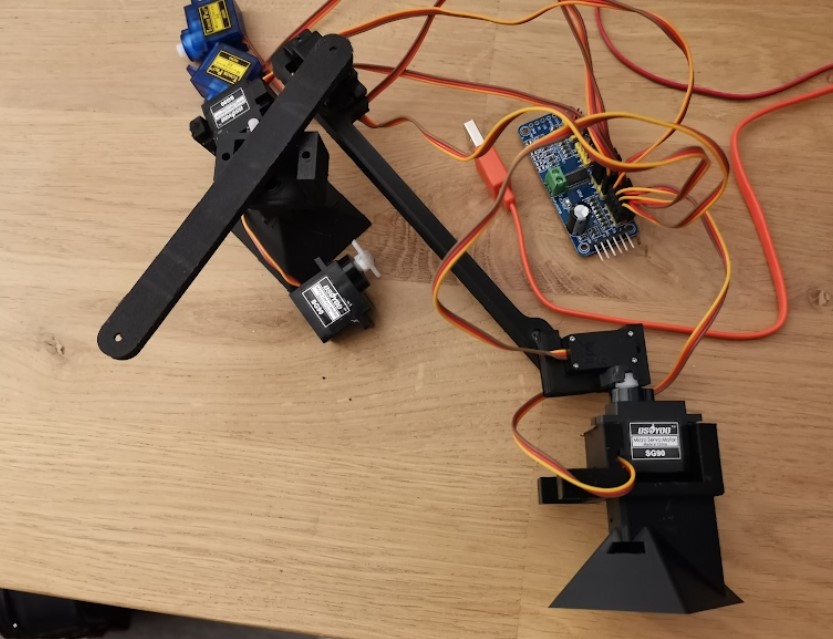
After assembling dose of octahedron, I began working on BILL-E. I started by placing all the servo that I will need in Fusion360. I work around them to connect them somehow.
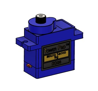
I’ll need to connect those SG90 servomotor from an old project. I also need a controller to move all the servos with limited numbers of output. I’ve found and I2C module to control the servos. I ordered this module to test lots of servo at once, but It may be very useful here.
To connect the servo together I’ll need a king of adapter. On side of the adapter will connect the body of the servo and the other one will connect to another servo output shaft.
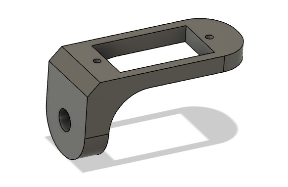
I tested several designs that didn’t fit to the servo mount. But then find the perfect fit. Even if the model is press-fit, I added tiny screw to fix servo bracket in place.
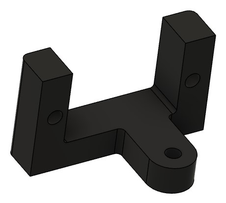
I worked on several parts to connect all the servo together.
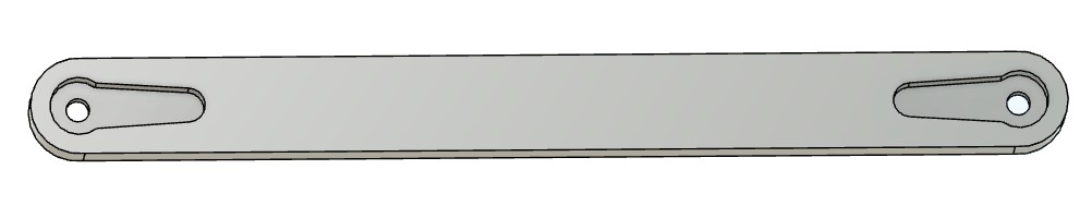
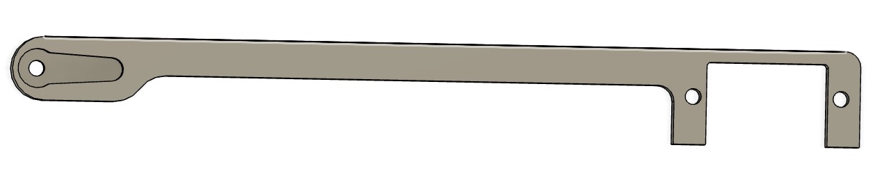
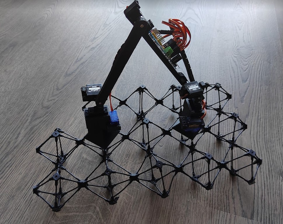
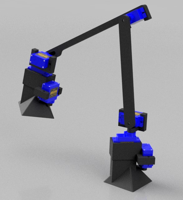
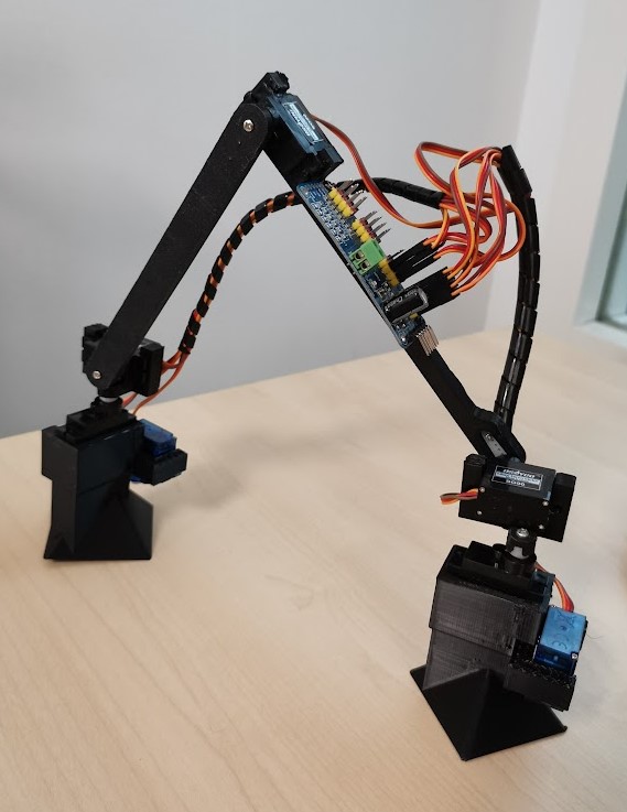
And one arm after another, I finally got something similar to BILL-E !
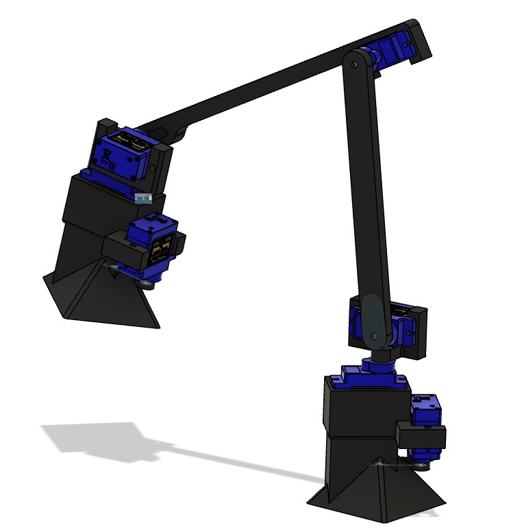
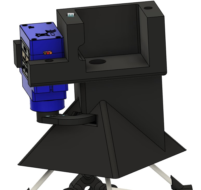
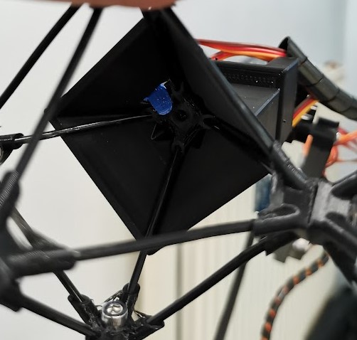
The most difficult part was surely the foot. First, the foot is an octahedron on one side, and a servo mount on the other. Connecting those two feature wasn’t easy. But I finnaly created two body that I fused later.
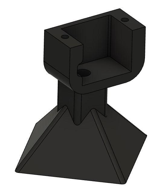
One of the side of the foot has a little hole to place the lock. The lock is in charge of Bill-E locking system.
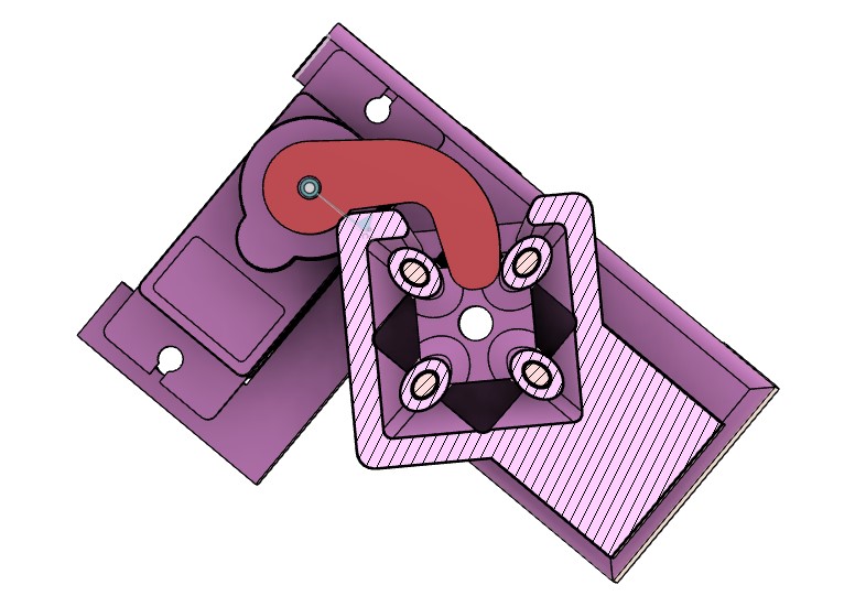
When the lock move, it allows Bill-e to move the other foot away, without falling.
I printed all the parts and finally make BILL-E alive !
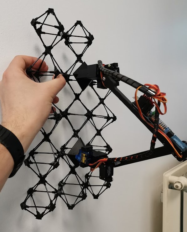
Now we need to test if he can climb using the locks.
As a result BILL-E can climb to the wall ! He is stick in place. However, I’m not sure that I will be powerful enough to climb like that. Statically it works !
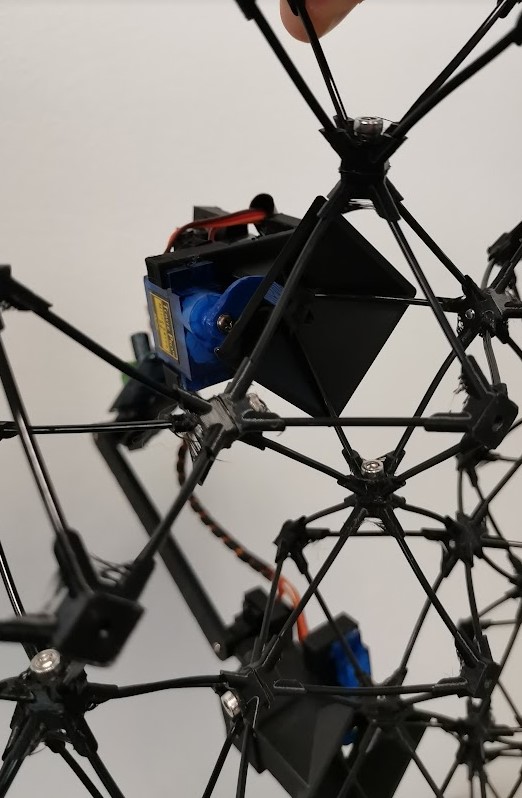
The lock is just long enough to block the octahedron in place a support the whole robot. However, the servo hasn’t much force to handle since, the force is transferred to the foot directly, the servo just slide in which require much less force.
Here is how BILL-E should walk :
Wiring
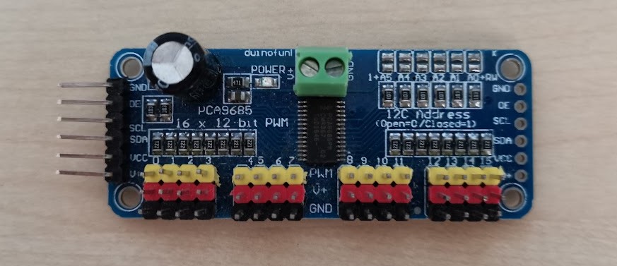
I BILLE was originally supposed to be controlled using this beautiful board :
Supported by an arduino nano. Since the arduino nano haven’t enough PWM ports to control every motors, I was planning to use the PCA9685 I2C Servo controller to move everything using only 2 pins.

Unfortunately the controller isn’t working at all. I can connect through I2C. But the basic example test or existing don’t work. It is easy to invert the polarity on this board, So I may have fried it before…
Fortunately I have a Teensy 3.5 in stock ! The teensy board have plenty of PWM ports. So I replace the Arduino nano by a teensy, wired the servos power on the PCA9685 and the signal pin on the PWM ports of the teensy.
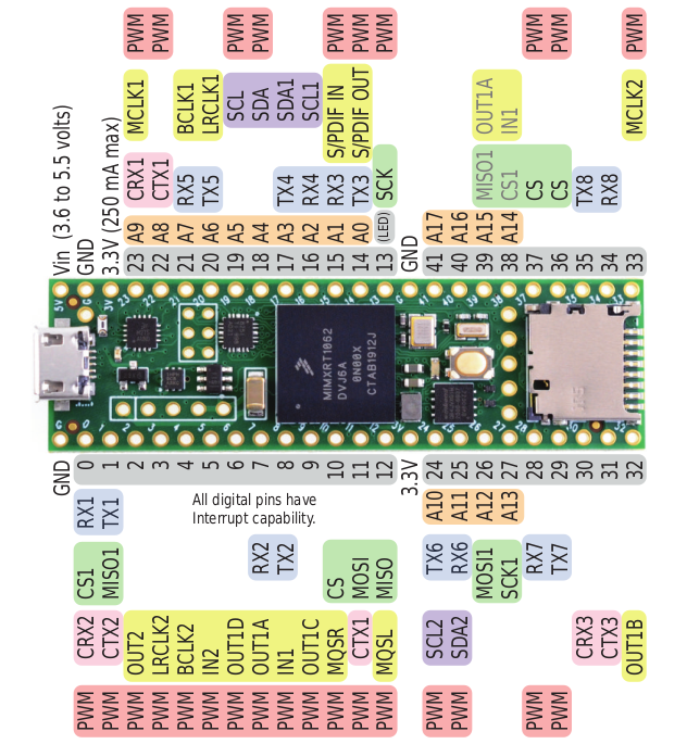
Here is the final Wiring :
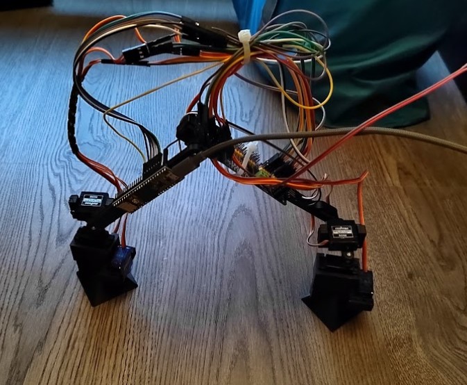
I agree with you, this isn’t the cutest robot I’ve seen. But in theory it may work !
I checked the connection twice and began to program.
Programming
Then goes the programming… First I want to warn you because, some pictures or video may be difficult to watch. Still no robots has been mistreaded turing the test phase.
I started by creating a platformio project. PlatformIO is an IDE for microcontroller programming embed in Visual Studio. It does exactly what Arduino IDE does but faster and using a powerful text editor.
To start a project in platformio, I created a new folder for the project. Inside that folder I created a new one named src and a file named platformio.ini
The platformio.ini file will tell Visual Code that this project need platformio. And obviously it should start.
Then We need to setup our environment. In platform IO, I had to install the Teensy Framework under the framework tab.
Inside the platformio.ini file I used the following lines :
[env:teensy]
platform = teensy
framework = arduino
board = teensy35
This being done, I created a src/main.cpp file which will be our main program.
When using Arduino IDE, you don’t need the Arduino library since it is already provided. But in pure C++ Files you need the library.
So, I created the program template like that :
#include <Arduino.h>

void setup(){

}

void loop(){

}
Then I need to check each servo to know which one is associated with which output. I created a very simple program to make one servo moving at once a few time. And I was taking notes of the wiring for each test. Here is the test program :
#include <Arduino.h>
#include <Servo.h>

Servo test;

void setup(){
    test.attach(2);
}

void loop(){

    for(size_t i(0); i < 10: i++){
        test.write(0);
        delay(500)
        test.write(50);
        delay(500)
    }

    while(true); //End of the program, infinite loop
}
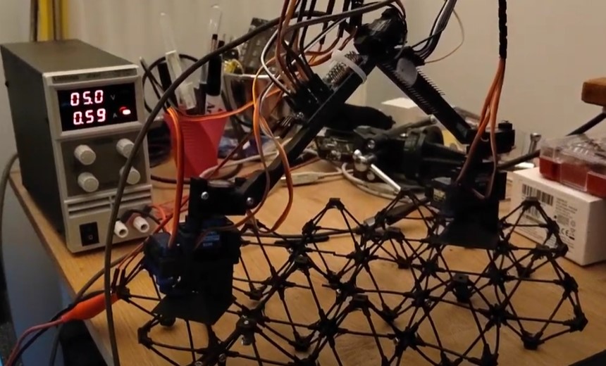
Here is the very firs test of BILLE alive :
Testing the motors without helping him wasn’t a good idea, but he survived ! After finding all the axis, I discovered that my power supply was giving 1.6A of current… Which is absolutely not a OK value. A bit of investigation and I discovered that one servo was smelling and very hot. This one died.
I replace the faulty servo and began to try a “zero” position.
#include <Arduino.h>
#include <Servo.h> //Importing the Servo library

Servo //Declaring all the servo
    footA,
    footB,
    kneeA,
    kneeB,
    body,
    lockA,
    lockB;

//Declaring function
void attachA(bool state)
void attachB(bool state)


void setup(){
    footA.attach(2); //Attach the Servo
    footB.attach(6);
    kneeA.attach(4);
    kneeB.attach(7);
    body.attach(5);
    lockA.attach(8);
    lockB.attach(3);
}

void loop(){
    //Zero position
    kneeA.write(0);
    kneeB.write(5);
    footA.write(60);
    footB.write(85);
    body.write(65);

    attachA(true);
    attachB(false);

    while(true); //End of the program, infinite loop
}

void attachA(bool state){
    if(state) lockA.write(10);
    else lockA.write(50);
}

void attachB(bool state){
    if(state) lockB.write(20);
    else lockB.write(50);
}
The zero position is basically, Bill-e attached to the lattice like that :
After a while I finally created another pos. The ultimate goal is to make a step ! Unfortunately the “knee” servo aren’t powerful enough for bille to operate on Earth.
But Hey ! Bill-e is made for spatial exploration. It can only operate on zero gravity… Not its fault !
Here is how he perform with gravity (I helped him a bit…) :
To handle that, I see 3 solution : - Send BILL-E in space. - Shorten the arm - Use stronger servo or use a reducer.
I tried the first solution, but old friend didn’t help…

So I tried to design shorter arms… I remove nearly 40mm of each arm. Let’s see !
Download
Here are the downloads if you want to reproduce BILL-E :