Output devices
For this week assignment we had to :
- Linked to the group assignment page
- Documented how you determined power consumption of an output device with your group
- Documented what you learned from interfacing output device(s) to microcontroller and controlling the device(s)
- Described your design and fabrication process or linked to previous examples.
- Explained the programming process/es you used.
- Outlined problems and how you fixed them
- Included original design files and code
- Included a ‘hero shot/video’ of your board
I choose to use servo motors and stepper motors this week. Servo motors are very easy to use, I want my final project to be as easy. Let’s get a servo to work and then reproduce the same function using a stepper motor !
Group assignment
For the motor, I tested several stepper motors and reducers. I have plenty of stepper motor from recycled project. Nowadays, you can find very cheap stepper motor since It became mainstream with inkjet printer and 3D printing. If you find an old copy machine somewhere. Open it up ! It contains doses of stepper. You can also by some cheap Chinese Stepper motor online. It works well for prototyping.
This being said, I worked mainly with two stepper motors. A NEMA17 Stepper motor and a NEMA23.
Here is a comparison with other actuators’ technology :
| Type | Advantages | Disadvantages |
|---|---|---|
| Brushed DC | Low cost, Easy to find or recycle | Need an encoder |
| Brushless | High torque | Need an encoder, Specific driver, Expensive |
| Stepper | Moderate cost, Easy to find or recycle | Complex control sequence, low speed |
For robot prototype, I need a powerful motor that can be controlled in position and speed. I want the whole product to be scalable. I choose the stepper motor because :
- I have plenty of them, and they are pretty common nowadays
- It can operate in a wide range of voltage (12v-24v and even 80v)
- High torque compared to Brushed DC
- Can be used with or without encoder
- I don’t need speed
So the main problem I should solve here is the control sequence. The motor should be as simple to use as a servo-motor, and Stepper motor are the exact opposite of control simplicity.
Here is the two Stepper I played with :
| Details | NEMA17 | NEMA23 |
|---|---|---|
| Size | 42x42x40mm | 57x57x56mm |
| Current | 2.0A | 2.8A |
| Stall Torque | 0.45N.m ~ 45.9 gf.m | 1.26N.m ~ 128.5 gf.m |
| Price | Moderate cost, Easy to find or recycle | Moderate cost, Easy to find or recycle |
| Resolution | 1.8° / revolution (200 step/revolution) | 1.8° / revolution (200 step/revolution) |
| Power consumption | 2.0A* 12v = 24W | 2.8A * 12v = 33.6W |
Torque
| Nema23 |
|---|
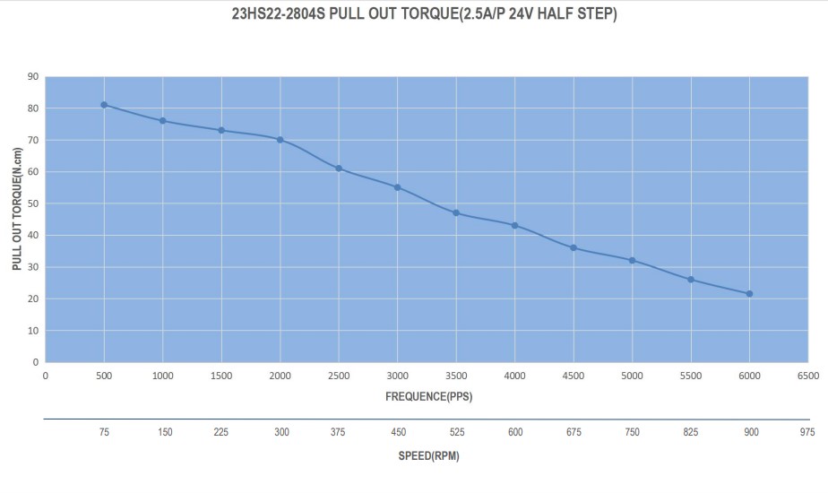 |
| Nema17 |
|---|
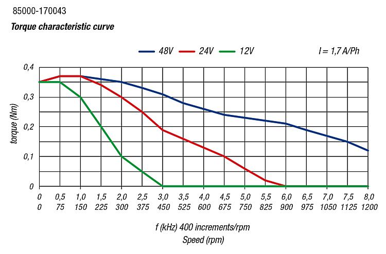 |
CAD
To include them in the project I’ve drawn those two motors during CAD Week
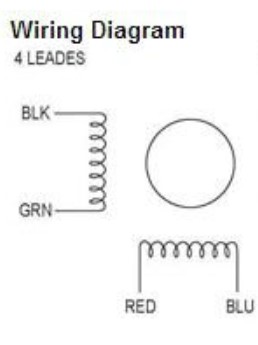
Stepper motor driver
Originnaly, I was planning to integrate this component directly onto my pcb board.
You can control stepper motors without drivers with a bunch of transistor arrays. Stepper motors are really straight forward. I did that once on an educational robot. But the problems is you need 4 outputs on you microcontroller to handle the control sequence. You need to power the coil in a defined controlled sequence to make the motor move.
Full step sequence
| Step | A | B | C | D |
|---|---|---|---|---|
| 1 | 1 | 0 | 0 | 1 |
| 2 | 1 | 1 | 0 | 0 |
| 3 | 0 | 1 | 1 | 0 |
| 4 | 0 | 0 | 1 | 1 |
Half-Step sequence
| Step | A | B | C | D |
|---|---|---|---|---|
| 1 | 1 | 0 | 0 | 1 |
| 2 | 1 | 0 | 0 | 0 |
| 3 | 1 | 1 | 0 | 0 |
| 4 | 0 | 1 | 0 | 0 |
| 1 | 0 | 1 | 1 | 0 |
| 2 | 0 | 0 | 1 | 0 |
| 3 | 0 | 0 | 1 | 1 |
| 4 | 0 | 0 | 0 | 1 |
I encountered two problems. First, When I designed the board, The driver chip wasn’t available on digikey or mouser. Also, I want my board to be compatible with different driver to ensure people can change the driver if he fry and use the driver alone if they don’t need my board anymore.
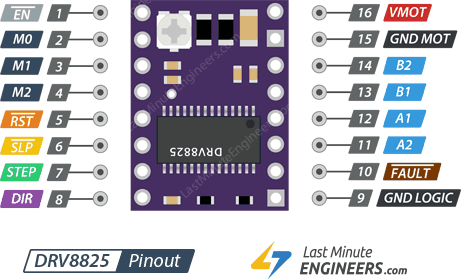
I had a lot of A4588 driver and Pololu DRV8825 at home. There is a way to create a board which is compatible with both of them. So I did. My board is compatible with both of those driver to handle the motor.
Using this driver save 1 output ont the microcontroller because I need :
- 1 pin for step
- 1 pin for direction
- 1 pin for enable
Each time you send a pulse on the step pin, the driver will increment to step according to the array above. As a result the motor will move by 1 step : 1.8 deg. The dir pin will change the direction in the step table. The enable pin power on and of the stepper motor. If the motor is idle and enabled, the output shaft is blocked. If you’re disabling the driver, the stepper will be free to move.
Servo motors
A servo motor is an actuator composed of 3 parts : - A motor (Muscle) - An encoder (Sense) - A control board (Brain)
The word servo has nothing to do with the brain but of all French people do this error since brain is “cerveau” in French which is pronounced like “servo”. Actually it means that the motors is under servitude. Even if I don’t like this idea, the motor is under strict position control. The role of the encoder is to give an information about where the motor is. Usually this data is given in degrees (rotation) or in millimeter/inches for linear actuators. According to this information, the logic has to turn on and of the motor in the according direction to move toward the required position specified by the user. In other words, Servomotor always where they are !
If I want my motor to point to 90°, it should reach that position and then stop until another request is sent. That is the main principle behind this actuator. I used a lot of servos in the past, mostly for robotics prototype. Such as BILLE from machine design week. They’re easy to use and to program.
Servomotor should receive on/off signal with a very precise timing. Most microcontroller have PWM outputs. PWM means Pulse Width modulation. This protocol is sending pulse at a precise frequency. Those pulses can vary in duration.

The servo are controlled using this principle where each pulse width is associated with an angular position. This is an efficient way to control something precisely without sending lots of data using a communication protocol. Instead, the trick is to use the ability of microcontroller to measure time precisely to transmit data using time has unit.
Personal assignment
Programming
For the programming part, I would like to use the servo interface to control the Stepper motor. Before doing this, I would like to know if the Stepper motor is working properly with my board.
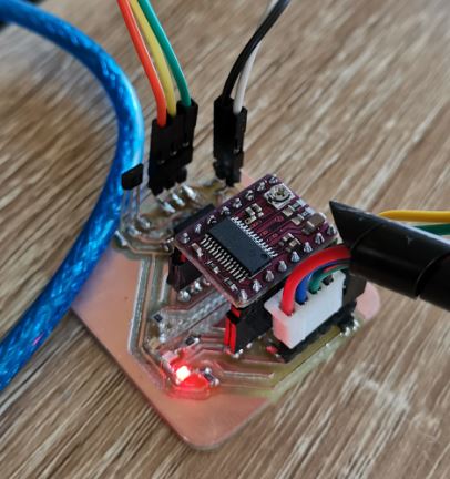
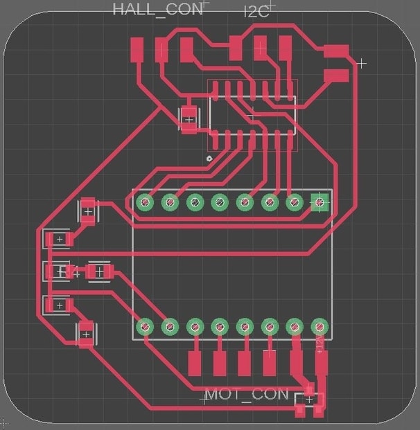
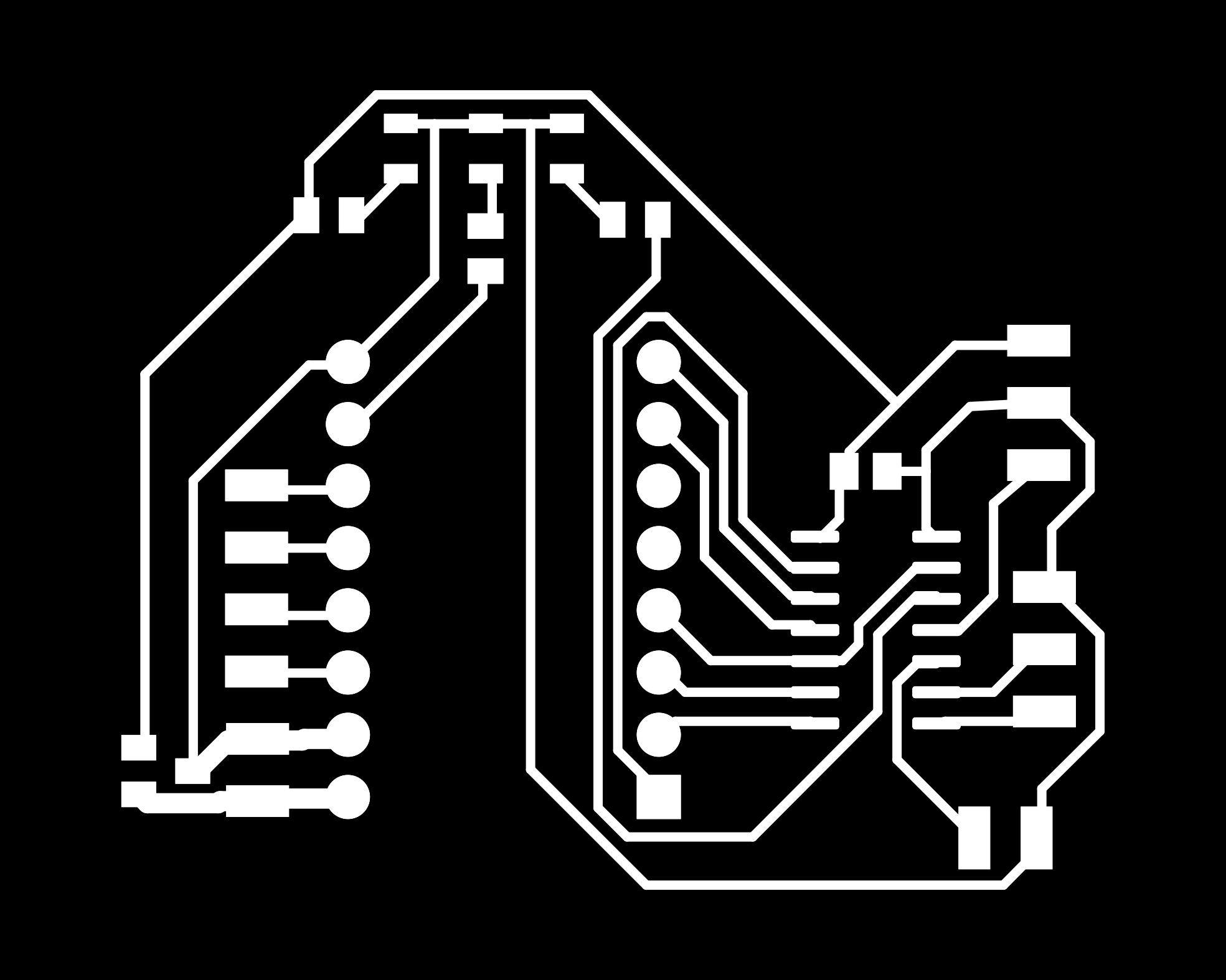
I recover the board I did during week 11 and completed the routing with the stepper driver.
I created a very simple code to test the stepper driver. Then, plugged the stepper driver STEP pin to the attiny, as well as the DIR and ENABLE pins. I completed the code made two weeks ago like this :
To accelerate the development process, I created a PlatformIO project. This project is available at the end of the page. I recovered the code I used two weeks ago and completed it with the stepper code. Here I’m enabling the stepper driver and setting various inputs and outputs.
Then in the loop function I’m creating two for loop to make the stepper do a revolution clockwise and then on anticlockwise.
#include <Arduino.h>
#define LED_PIN 13
#define HALL_PIN 8

#define ENABLE_PIN 0
#define DIR_PIN 1
#define STEP_PIN 2

void setup(){

  // Input/Output setup
  pinMode(LED_PIN, OUTPUT);
  pinMode(HALL_PIN, INPUT_PULLUP);

  pinMode(ENABLE_PIN, OUTPUT);
  pinMode(DIR_PIN, OUTPUT);
  pinMode(STEP_PIN, OUTPUT);

  //Enable the stepper stepper
  digitalWrite(ENABLE_PIN,1);
}

void loop(){
  digitalWrite(DIR_PIN,HIGH); // Enables the motor to move in a particular direction
  // Makes 200 pulses for making one full cycle rotation
  for(int x = 0; x < 200; x++) {
    digitalWrite(STEP_PIN,HIGH);
    delayMicroseconds(500);
    digitalWrite(STEP_PIN,LOW);
    delayMicroseconds(500);
  }
  delay(1000); // One second delay
    digitalWrite(DIR_PIN,LOW); //Changes the rotations direction
  // Makes 400 pulses for making two full cycle rotation
  for(int x = 0; x < 400; x++) {
    digitalWrite(STEP_PIN,HIGH);
    delayMicroseconds(500);
    digitalWrite(STEP_PIN,LOW);
    delayMicroseconds(500);
  }
  delay(1000);

}
I uploaded the code into the board. And started the power supply. For some reason, the big capacitor under the stepper driver exploded ! I may have soldered it the wrong way… But I wonder why it didn’t explode before…
Anyway, I soldered a new one and everything else was OK ! Hopefully !
However, the motor doesn’t spin… I look to the driver datasheet and seen this schematic :
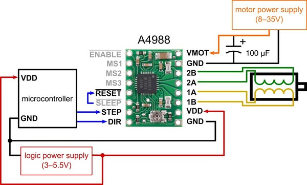
Obviously I forgot to power the VDD Pin. So the driver isn’t supply with logic power… I changed that on a new board design. At the same time I got an idea.
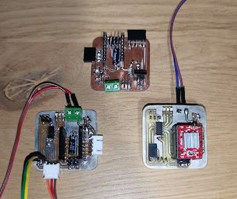
Remember the previous board ? Look at the new one :
| Old | New |
|---|---|
|
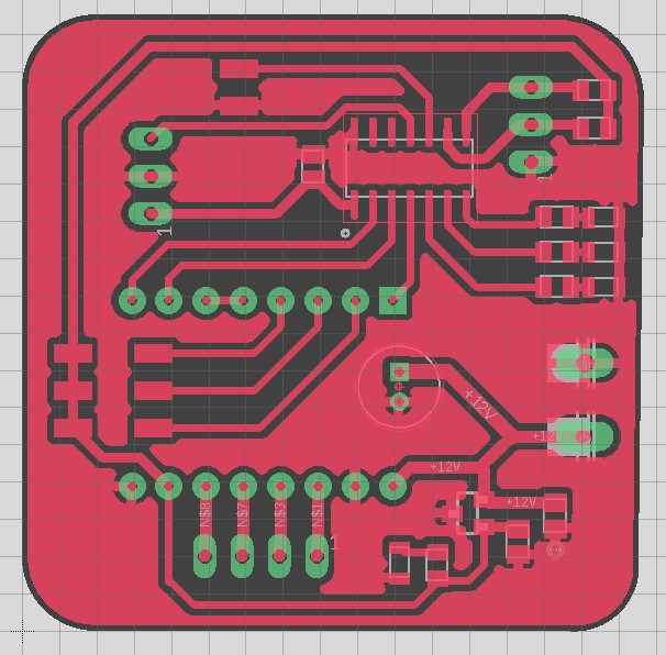 |
As you can see there is a lot of Improvement ! Big step up in electronic design !
So there is a lot to say about it… Let’s begin by something cool. Do you see the three bottom pins of the Attiny of the old board ? Those pins were connected to the driver mode pins. These pins are used to switch between step mode (full step, half step, 1/4, 1/8 …).
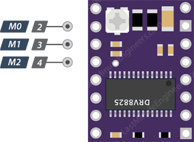
Usually when doing 1 step, the stepper motor will turn by 1.8°. But you can be smoother by switching to 1/4 step. This way the motor will need 4 step to make 1.8°. The moves are smoother, the motor is quieter. And the acceleration curve is also smoother.
| M0 | M1 | M2 | Microstep Resolution |
|---|---|---|---|
| Low | Low | Low | Full step |
| High | Low | Low | Half step |
| Low | High | Low | 1/4 step |
| High | High | Low | 1/8 step |
| Low | Low | High | 1/16 step |
| High | Low | High | 1/32 step |
| Low | High | High | 1/32 step |
| High | High | High | 1/32 step |
Those modes require 3 pins to be changed… But I need pins for communication and sensors… So I decided to used jumper instead Those pins will be connected to male pin header. I’m using jumper, I’ll be able to select the mode manually.
I milled the board and try again my program.
This time : The motor make a little noise but don’t turn…
I try different mode configuration without result.
I thought about a pin selection problem.. So I refactored the way I was managing pins in the program.
I created a pin.h file in the src folder.
#pragma once

namespace Pin{
    const int
    ADRESS  = 0x08,
    SERVO   = 6,
    SPEED   = 7,
    LED_G   = 3,
    LED_B   = 4,
    LED_R   = 5,
    SENSOR  = 8,
    DIR     = 0,
    STEP    = 1,
    ENA     = 2;

} // namespace Pin
Then I included the file in the main.cpp.
#include <Arduino.h>
#include "pin.h"


void setup(){

  // Input/Output setup
  pinMode(Pin::LED_B, OUTPUT);
  pinMode(Pin::LED_R, OUTPUT);
  pinMode(Pin::LED_G, OUTPUT);

  pinMode(Pin::SENSOR, INPUT_PULLUP);

  pinMode(Pin::ENA, OUTPUT);
  pinMode(Pin::DIR, OUTPUT);
  pinMode(Pin::STEP, OUTPUT);

  //Enable the stepper stepper
  digitalWrite(Pin::ENA,1);
}
No the motor is running properly, I can measure the current flow using my power supply :
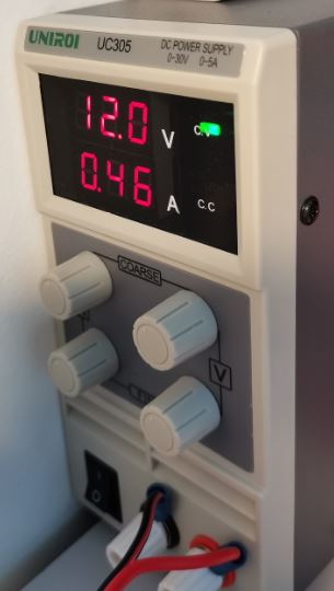
So the overral stepper consumption is
The problem with the previous code is that I cannot do anything else while the motor is working. I cannot check the hall effect sensor for instance. So I had to refactor the Stepper part also.
I created a new file named Stepper and implements non-blocking stepper control. At each iteration of the main loop, I execute the updateStepper function. This function will check if the stepper need to step. If it needs to, It executes one step or two. Then the function is called again.
To control the speed of the stepper, I’m calculation the delay between to step. This will be part of the step condition. If the motor need to move and if the last step was more than the delay ago. Then, do a step.
Here is the class I came up with :
#pragma once
namespace Stepper{

    const int range = 360;

    void init();
    void update();

    void enable(bool = true);
    void disable();

    bool isEnabled();

    void step();

    void setTarget(int);
    void setDirection(bool);
}
#include "stepper.h"
#include "pin.h"
#include <Arduino.h>

namespace Stepper{

  int target = 0;
  int position = 0;

  int speed = 800; // step/s
  int mode = 4;

  unsigned long period = 1000000 / speed / mode;
  unsigned long tlastStep = 0;

  bool dir = false;
  bool enabled = false;

  void init(){
    pinMode(Pin::DIR, OUTPUT);
    pinMode(Pin::ENA, OUTPUT);
    pinMode(Pin::STEP, OUTPUT);

    setDirection(true);
    setTarget(0);
    enable(true);
  }

  void update(){
    if(target - position != 0){
      if((target > position) != dir){
        setDirection(!dir);
      }
      if(micros() - tlastStep >= period){
        step();
      }
    }
  }

  void setDirection(bool ndir){
    dir = ndir;
    digitalWrite(Pin::DIR, dir);
  }

  void setTarget(int ntarget){
    target = ntarget*35;
  }

  void step(){
    digitalWrite(Pin::STEP,HIGH);
    delayMicroseconds(8);
    digitalWrite(Pin::STEP,LOW);
    delayMicroseconds(8);
    position += dir ? 1 : -1;
    tlastStep = micros();
  }

  void enable(bool state){
    enabled = state;
    digitalWrite(Pin::ENA, !state);
  }

  void disable(){
    enable(false);
  }

  bool isEnabled(){
    return enabled;
  }

} // namespace Stepper
I also implemented a class for controlling the LEDs :
#pragma once

#define PIN_LED_G 3
#define PIN_LED_B 4
#define PIN_LED_R 5

namespace Led{
    void init();

    void ledR(bool);
    void ledG(bool);
    void ledB(bool);

    void test();
    void blink();
}
#include "led.h"
#include <Arduino.h>

#include "pin.h"

long lastBlink = 0;

bool ledGState = false;
bool ledRState = false;
bool ledBState = false;

namespace Led{
  void init(){
    pinMode(Pin::LED_R, OUTPUT);
    pinMode(Pin::LED_G, OUTPUT);
    pinMode(Pin::LED_B, OUTPUT);

    digitalWrite(Pin::LED_R, LOW);
    digitalWrite(Pin::LED_G, LOW);
    digitalWrite(Pin::LED_B, LOW);
  }

  void ledR(bool state){
    if(ledRState != state){
      digitalWrite(Pin::LED_R, state);
      ledRState = state;
    }
  }

  void ledG(bool state){
    if(ledGState != state){
      digitalWrite(Pin::LED_G, state);
      ledGState = state;
    }
  }

  void ledB(bool state){
    if(ledBState != state){
      digitalWrite(Pin::LED_B, state);
      ledBState = state;
    }
  }

  void test(){
    ledR(true);
    delay(1000);
    ledG(true);
    delay(1000);
    ledB(true);
    delay(2000);
    ledR(false);
    delay(1000);
    ledG(false);
    delay(1000);
    ledB(false);
  }

  void blink(){
    if(!ledGState){
      if(millis() - lastBlink > 2000){
        ledG(true);
        lastBlink = millis();
      }
    }else{
      if(millis() - lastBlink > 80){
        ledG(false);
        lastBlink = millis();
      }
    }
  }
}
As you can see, everything in those class are based on the millis() function. This function returns the number of milliseconds that have passed since the beginning of the program. This way, I can keep track of the time passed since the last step or LED blink. I’m aslo using the micros() function to get the delay in microseconds.
Now we have a way to control the stepper motor using the SetTarget function. The next step is to communicate with the board to control the motor.
Fabrication
I created a lot of board this week ! Each time with a mistake to solve…
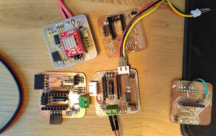
I began by testing the board from week 9. Then Redesign the whole board and change a feature or two each time.
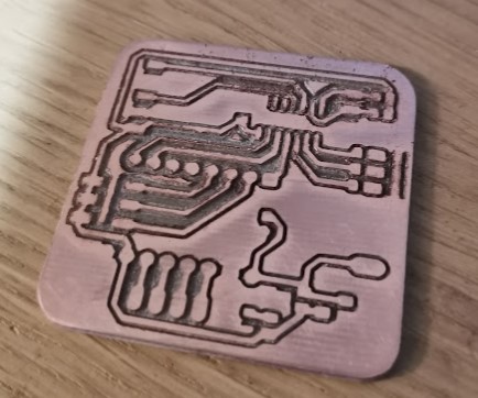
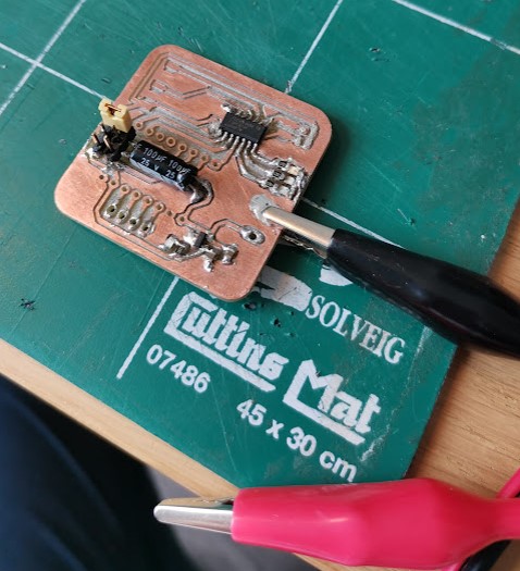
I ended up with this beautiful board :
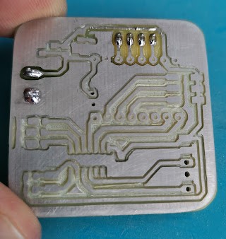
I began by milling this board :
Then I soldered all the SMD component.
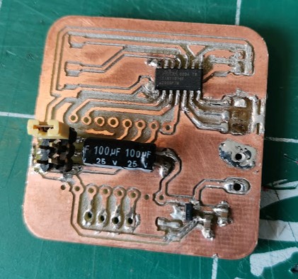
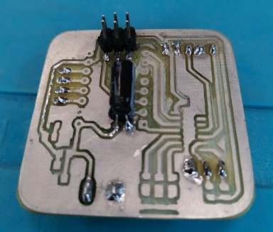
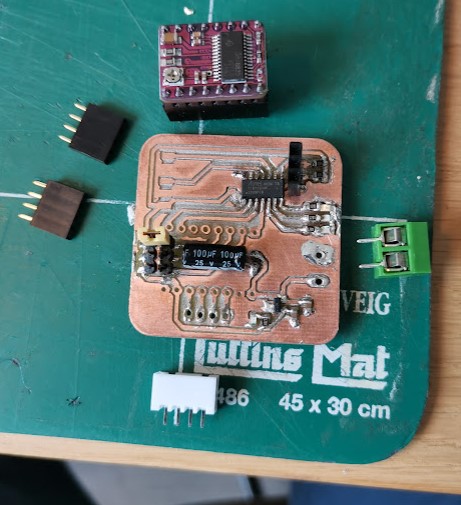
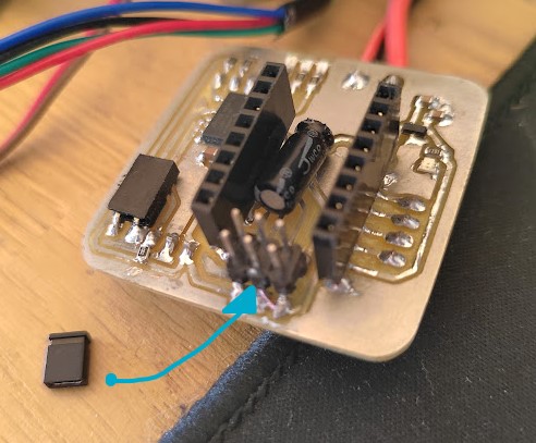
It worked pretty nicely, but I had lots of problems with the connectors. So I decided to mount them at the bottom of the board.
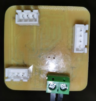
However, I won’t be able to mount the board directly on the motor like that :
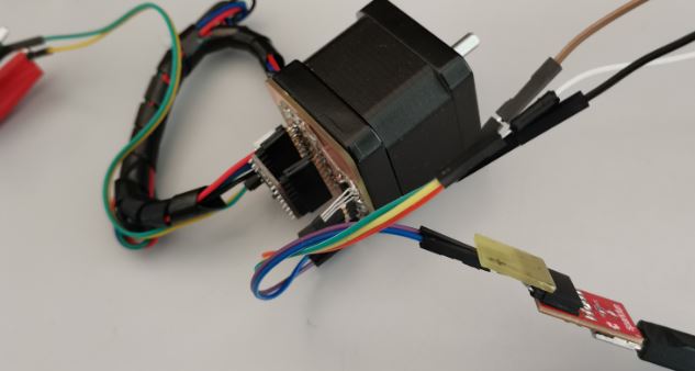
I may need a 3D printed case for that purpose. I also tried coled tining. Furthermore, I bought Chemical tin on Gotronic. It is basically compose of acid with Tin ion in it.
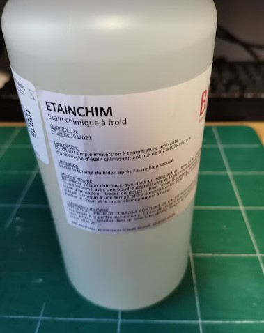
When the copper board is immersed in the solution, tin ion will be fixing on the copper to deposit a thin layer of tin. The board was much easier to solder after that !
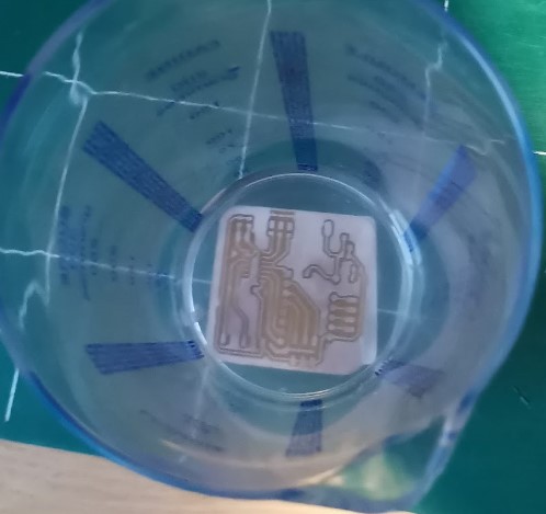
The board is also more protected against corrosion problems.
I tested for shortcut on each of my board to avoid exploding capacitors again !
Downloads
Board :
Code : - PIO smartStepper