Wildcard week
This week we had to cover a wild subject of our choice.
I decided to play with compliant mechanism.
Compliant mechanism is a very interesting subject and also very related to digital fabrication and mechanical engineering.
A compliant mechanism, as opposed of rigid body, has some degree of freedom from the flexibility of its components.
One mainstream example is the nail clipper.

When you press the handle of a nail clipper, the two lower blade will get closer and eventually put some force onto the nail et cut through it. This kind of usage is advantageous for several reasons.
First, it reduces the production and Assembly cost in most case. But reducing the number of component of a system you reduce the cost ans the system complexity. This kind of system don’t need lubrication since there is no friction during repeated moves. The absence of friction leads the system to buy very quiet and more durable.
Recently compliant mechanism had been used in extreme precision positioning. Since the system doesn’t wear, the precision of a compliant system is constant in the time.
Even designing compliant mechanism may seem strange and uncommon, there is a lot of similarities to conventional mechanism.
First, let deal with Mechanical properties :
Each material have several physical properties. All materials can be classified using these properties. In mechanical engineering we use a simple chart to describe the material behavior undo force or deformation.
This is defined by the Hooke’s law. This law can be simplified be considering each rigid part as a spring. When we pull onto the part it may stretch of brake. Actually the reality is a bit more continuous. Every material have 3 deformation state :
- Elasticity
- Plastic deformation
- Fracture

Actually there are more than 3… but it’s OK for know :D
Here is a pretty good tutorial to estimate material property and understand what’s going on in the material.
I plan to design simple compliant mechanism and test it using different material. I also want to simulate deformation using Fusion 360 static simulation environment.
Designing a plier
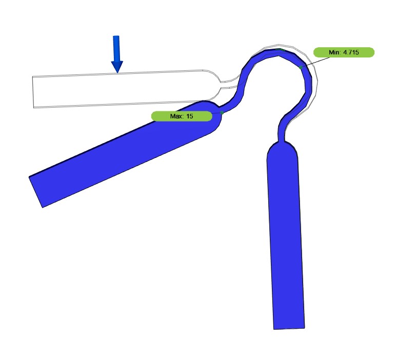
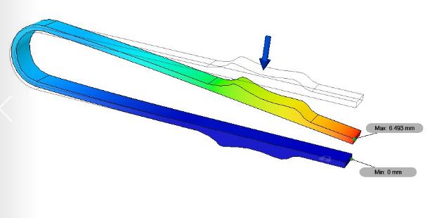
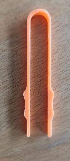
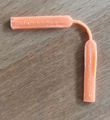
I design a simple plier because I broke very often my SMD parts while soldering them. I designed a very thin U-shaped plier using Fusion. Here is the simulation. I applied 50g of weight onto one side of the plier and constrained the other side.
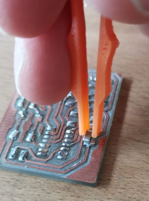
I also 3D printed the plier. The result is perfect ! I can hold my SMD capacitor while soldering ! :)
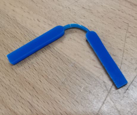
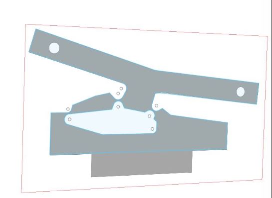
One very famous compliant mechanism is the bistable switch. I took a picture online to get the right shape of the switch. I then imported the picture in fusion 360 as a canvas to sketch onto it. Here is the original file.
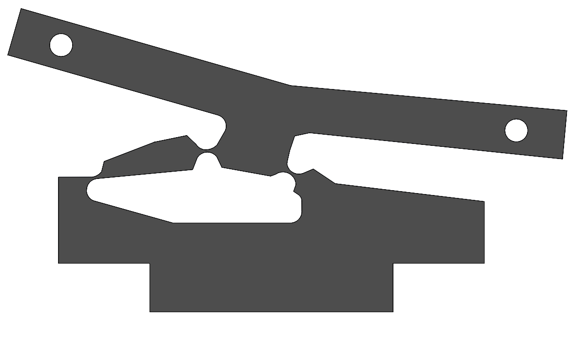
You may have to resize the canvas when imported. It simply uses the graduation of the grid to get almost the same dimension as the original model.
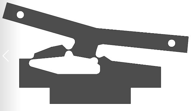
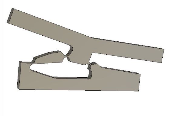
I use lines and arc to draw around the model and got that sketch and extrude it by 5 mm :
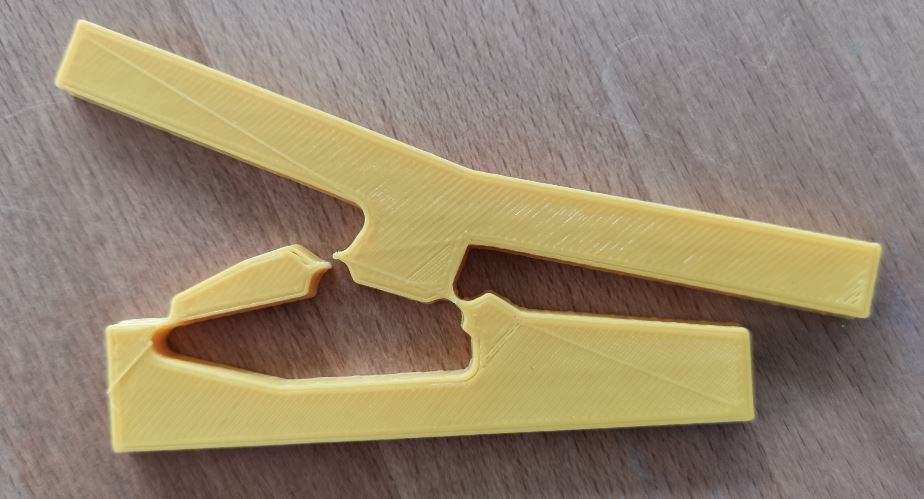
After 3D printing the model, here is how it looks :
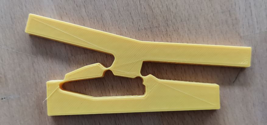
The switch seems functional and took around 1 hour to print.
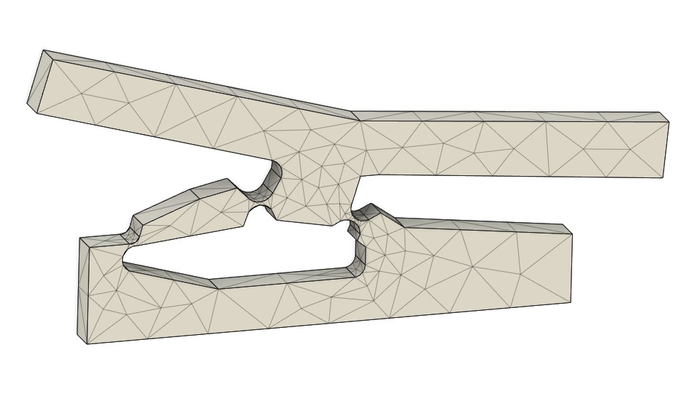
On the simulation the bistable state doesn’t work. Fusion don’t simulate the full move of the part…
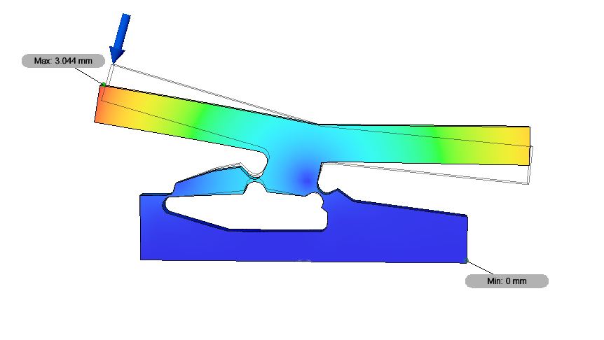
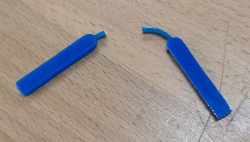
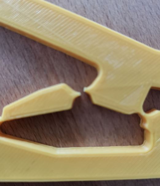
After toggling the switch around twenty times it broke. I think the joint were a bit to thin and the kinematics may not be very accurate…
I also tried to cut those part using the laser cutter. But I forgot to take the kerf in account.
Here is the Plexiglas version of the switch :
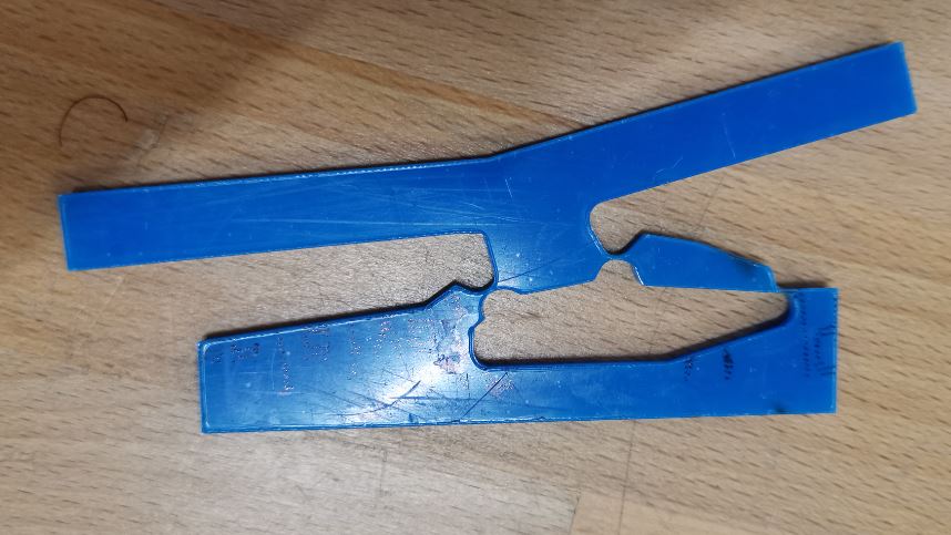
And without surprise it broke !
A very simple compliant joint is the revolution joint. This joint is simply composed of a thin arc line
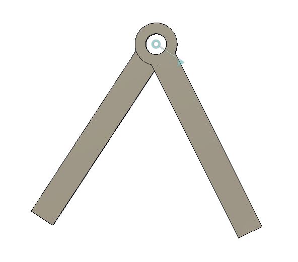
As you may see in the video if I go too far, the joint doesn’t restore its original position. It is deformed forever.
The Plexiglas version failed… Plexiglas is very brittle…