7. Electronics design
   group project:
      use the test equipment in your lab to observe the operation
         of a microcontroller circuit board
   individual project:
      redraw an echo hello-world board,
      add (at least) a button and LED (with current-limiting resistor)
      check the design rules, make it, and test it
      extra credit: simulate its operation
Redesigning the board
For my echo hello-world board, I decided to use a board with an ATTiny412 chip along with both the echo and blink combined to meet the assignment requirement. I used Autodesk Eagle to redraw my PCB.
First, some new libraries are needed as the pre installed libraries do not have the symbols and footprints we need to map out the echo/blink board.
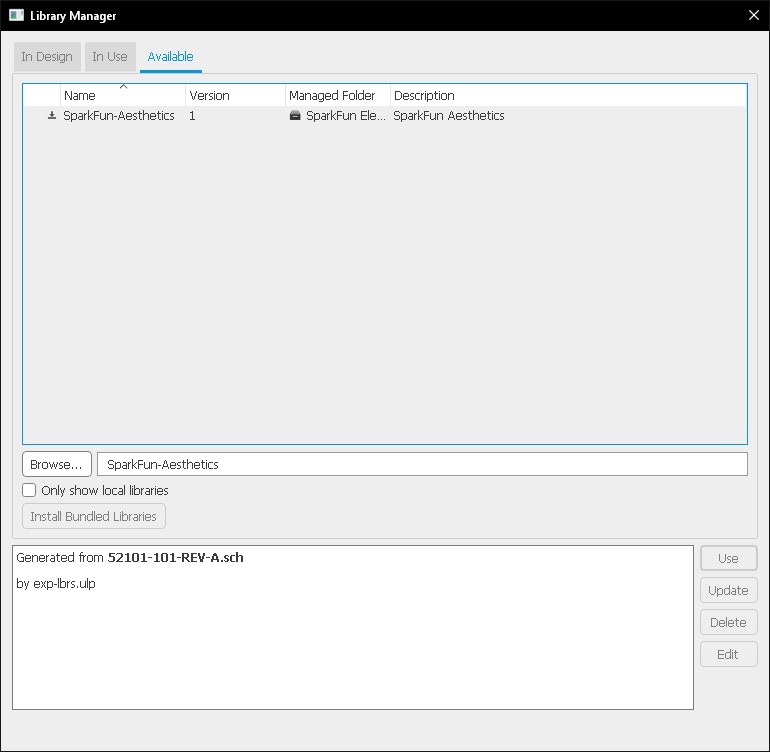
We need the following libraries: - SparkFun-Aesthetics.lbr (in library manager) - fab_new.lbr (use folder)
Downloading the libraries is simple, requiring that you either use the library manager under the library tab and search for common libraries.
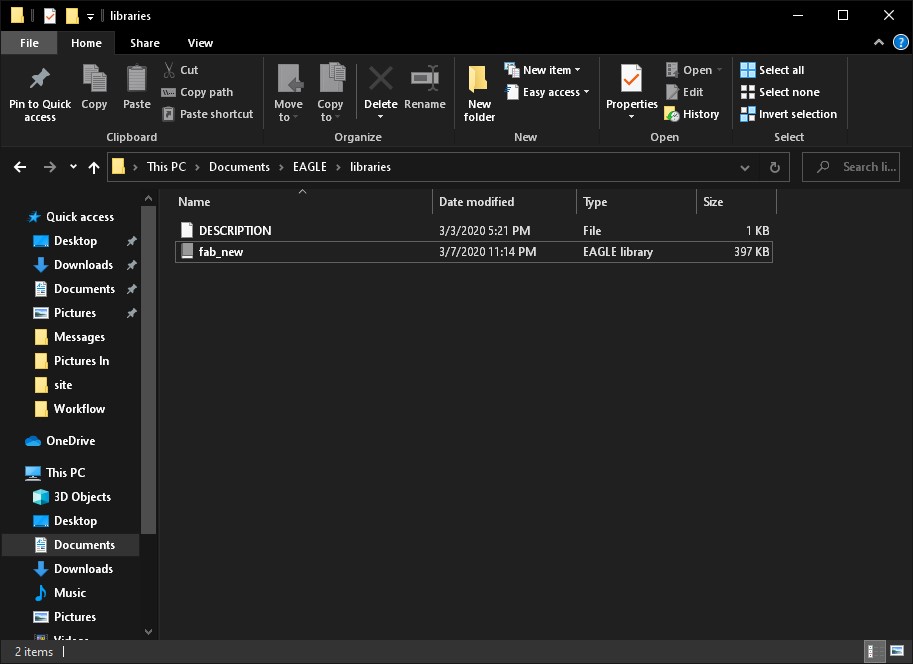
Or navigate to ./Documents/EAGLE/libraries and place your file with the .lbr extension into it. Please note that these .lbr files are created using text so if simply saving a notepad file with the .lbr extension will create a library.
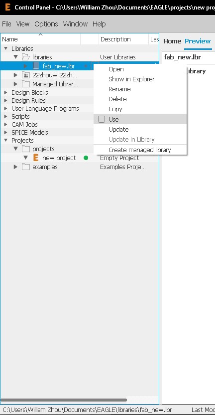
To use your libraries in your projects, you first need to enable it.
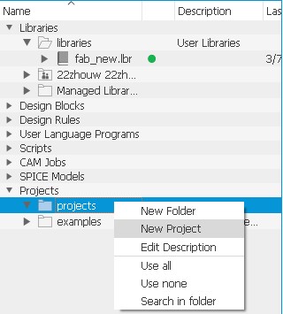
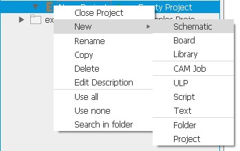
Once we have done that, it is time to create a new project.
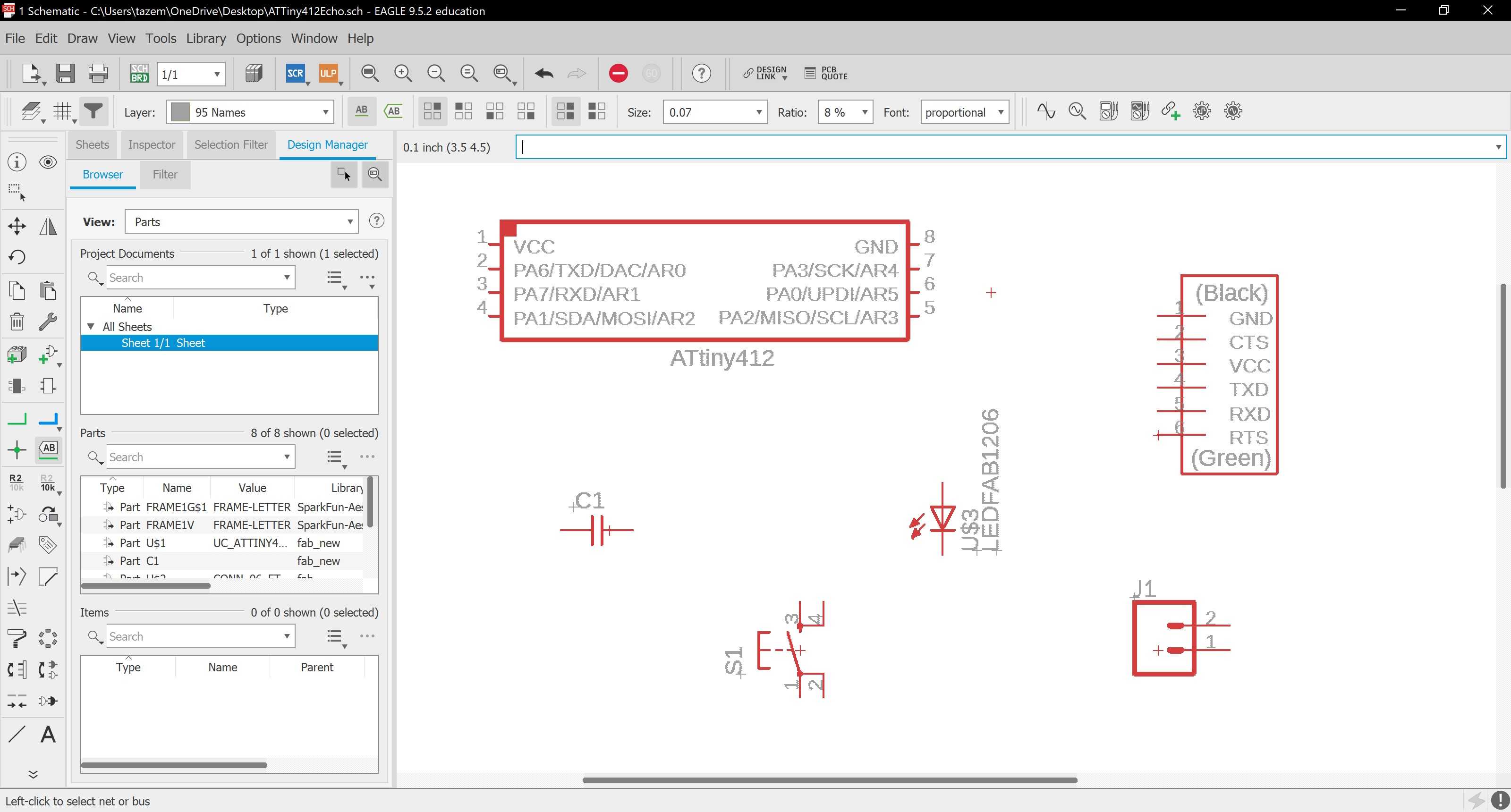
From this, we will create a schematic of our board.
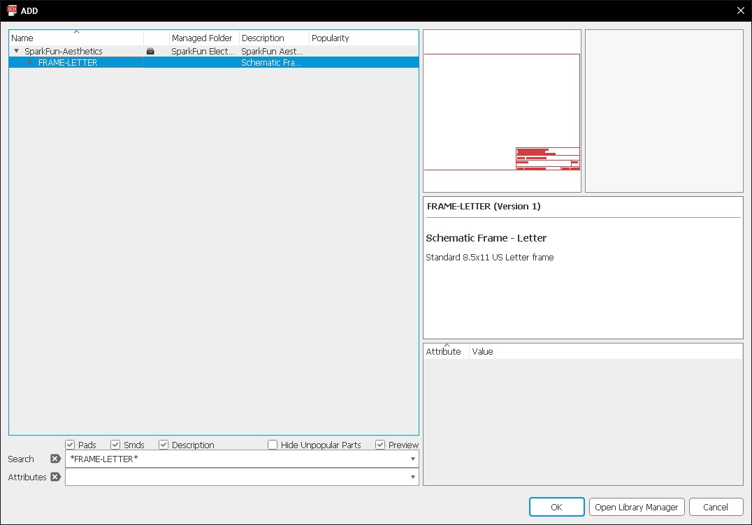
Adding symbols into your schematic requires the use of the Add Tool. This search tool is very literal so it is best to use asteriks as a wildcard for any number of characters (e.g. /FRAME/ or /FRAME-LETTER/).
We will first add in a FRAME-LETTER to give us a reference in our schematic.
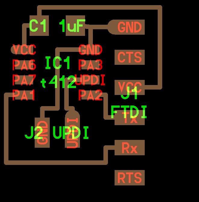
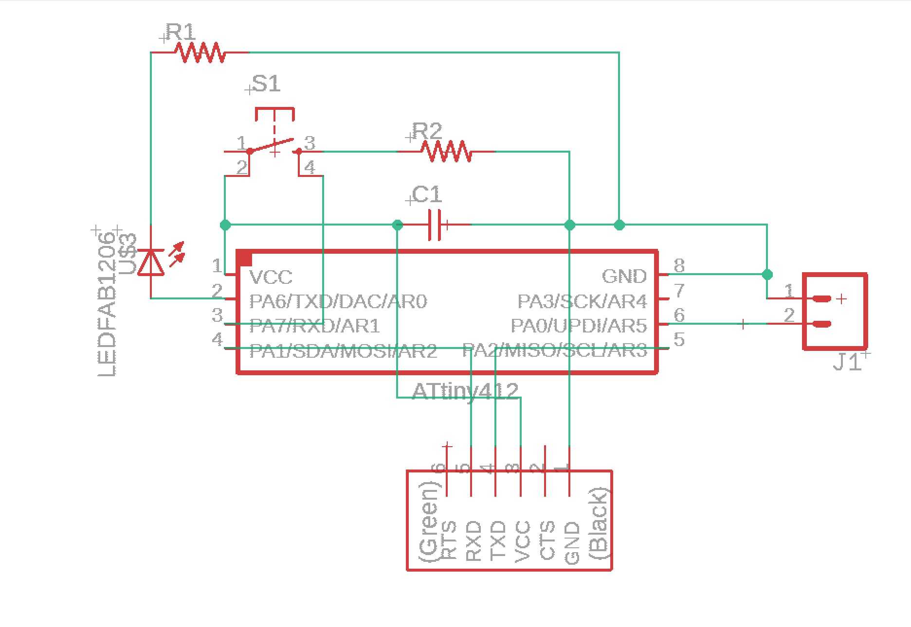
Now these are the two schematics that we will combine to make this board.
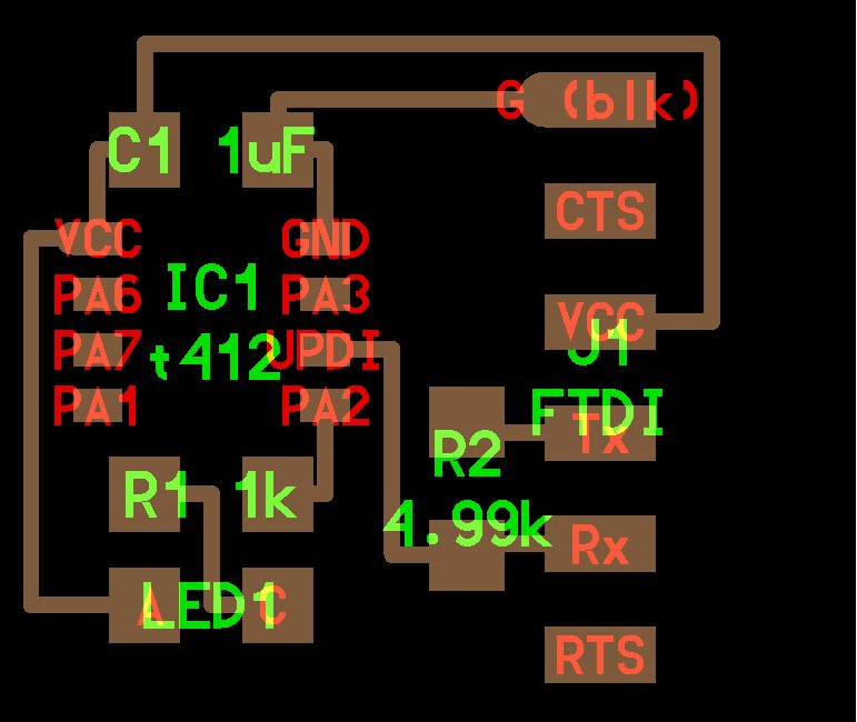
I added the components needed for this board.
Then, I wired the proper connections between each component.
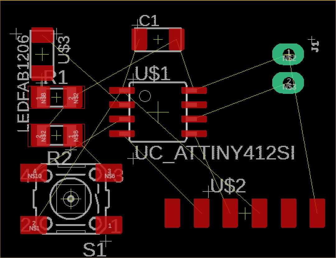
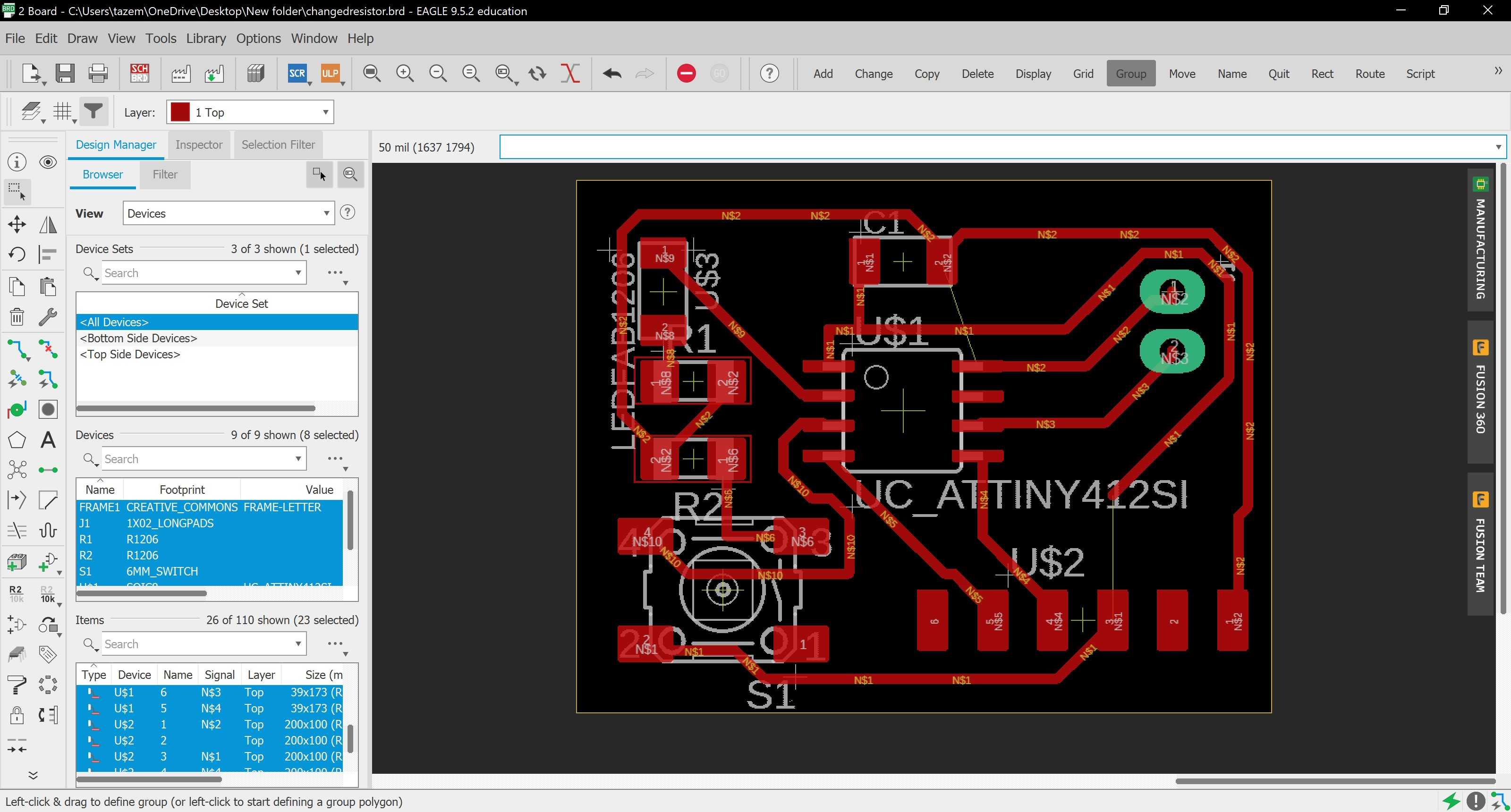
Now, I switched to the Board to start figuring out the placements of components.
I tried to make my design as small as possible along with positioning the components to make soldering as easy as possible.
Next, now that I have the positioning of my board down, it is time to autoroute it. I first downloaded a .drc file for Bantam Tool’s Othermill that I will import into EAGLE. This will make our traces the desired width when milling using a certain bit.
When the zip is downloaded, extract the files. Under Edit>Design Rules, load the file named OthermillDRC_1_64_v2.drc as a setting and click Apply.
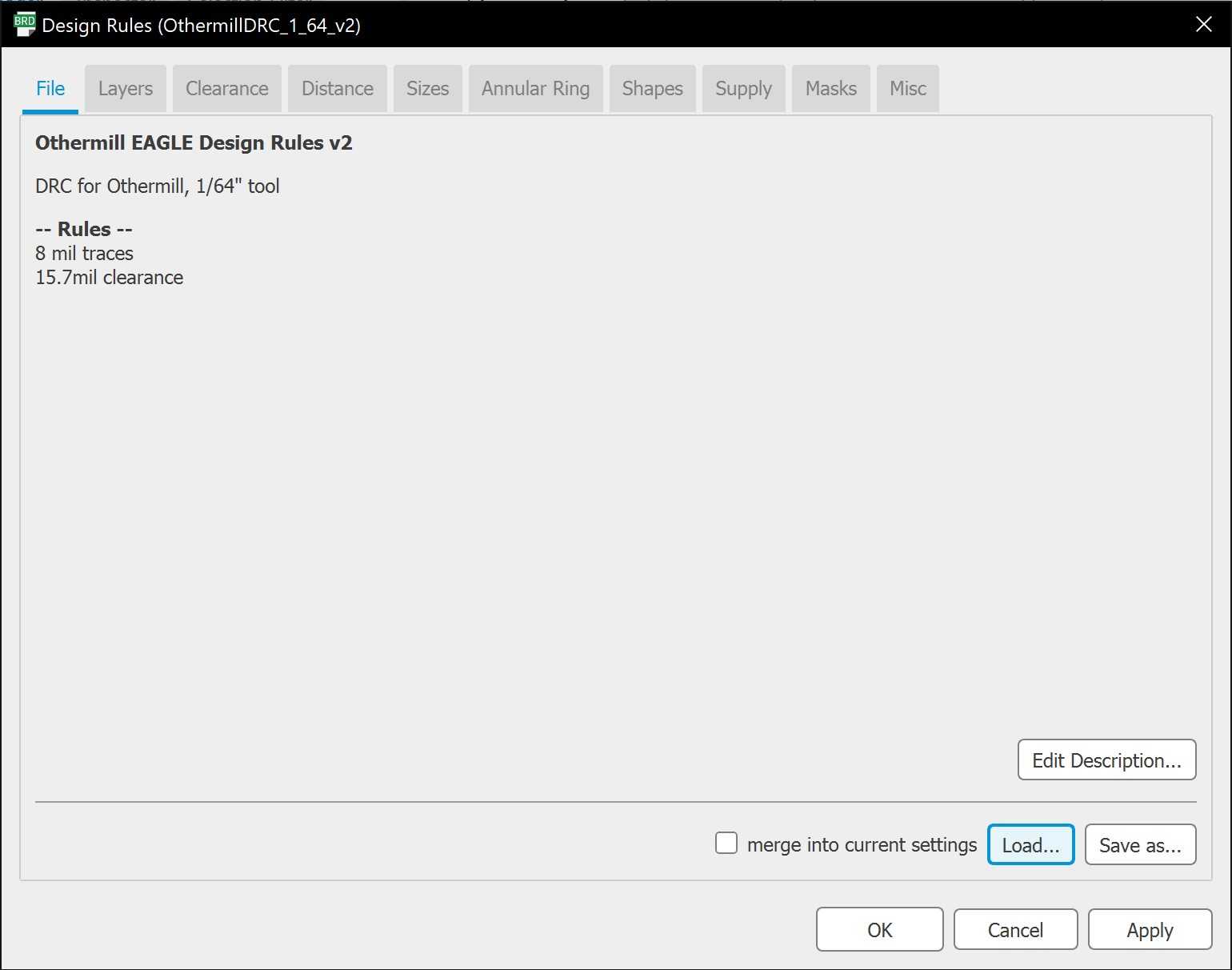
As we are using the Single-Sided FR-1, we only have a Top Layer and that will be the only layer selected for this board. In addition the effort will be set to High.

Start the autoroute and it will give you a variety or autoroutes to choose from. Choose the one you like with the highest percentage completion and evaluate it.
This is what my final traces looks like:
To mill out my board, simply take the .brd file of your project and import that into Bantam Tools. This skips the need for using tools such as Fab Mods or Modules.
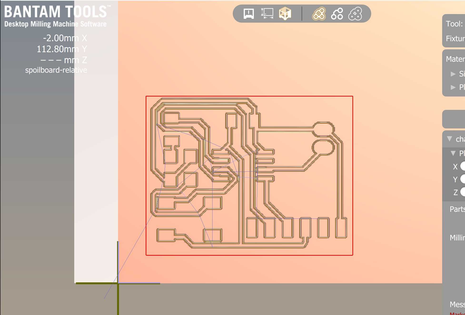
I milled this out first using a 1/64th bit and later on using a 1/32th bit to widen the traces and cut out the outline.
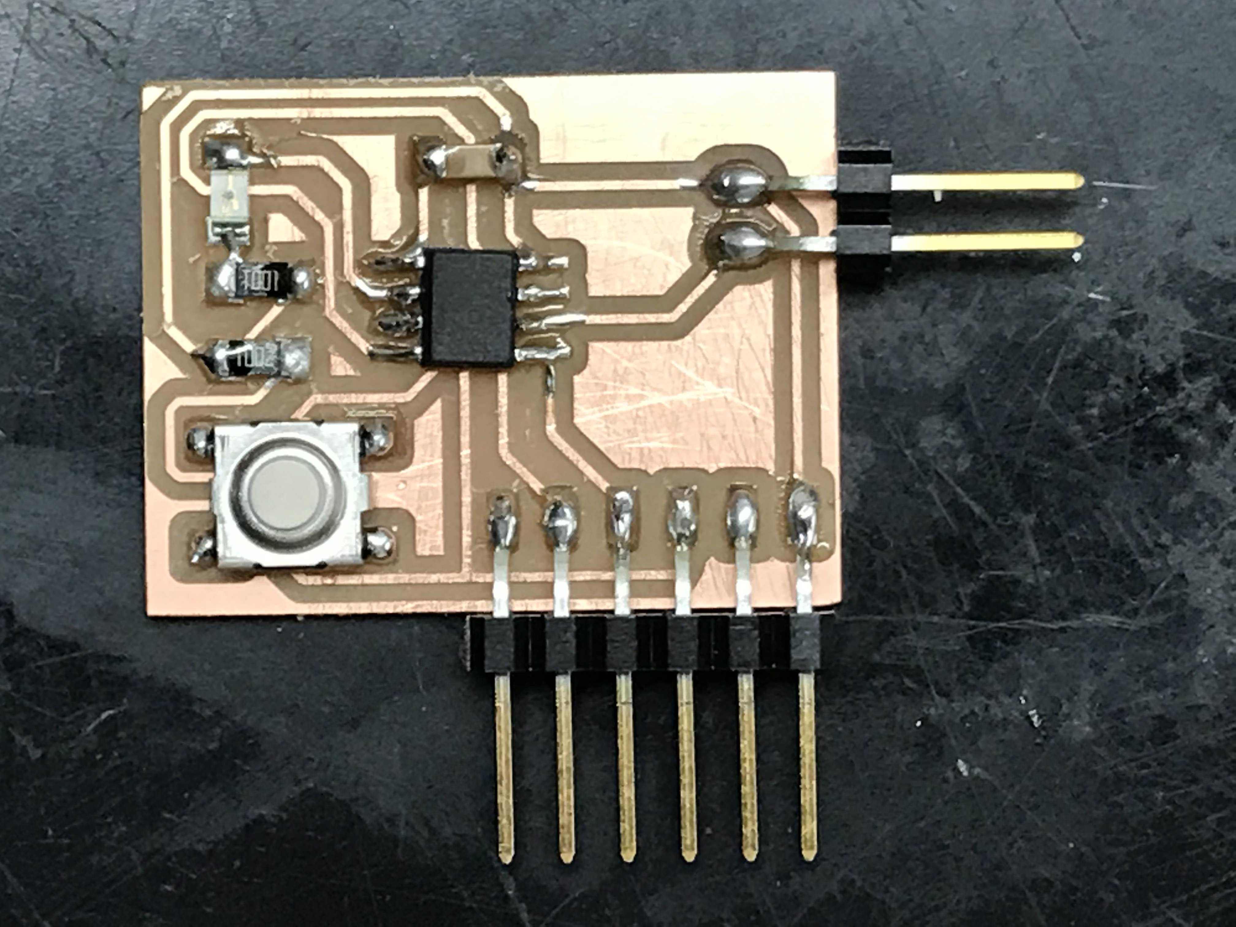
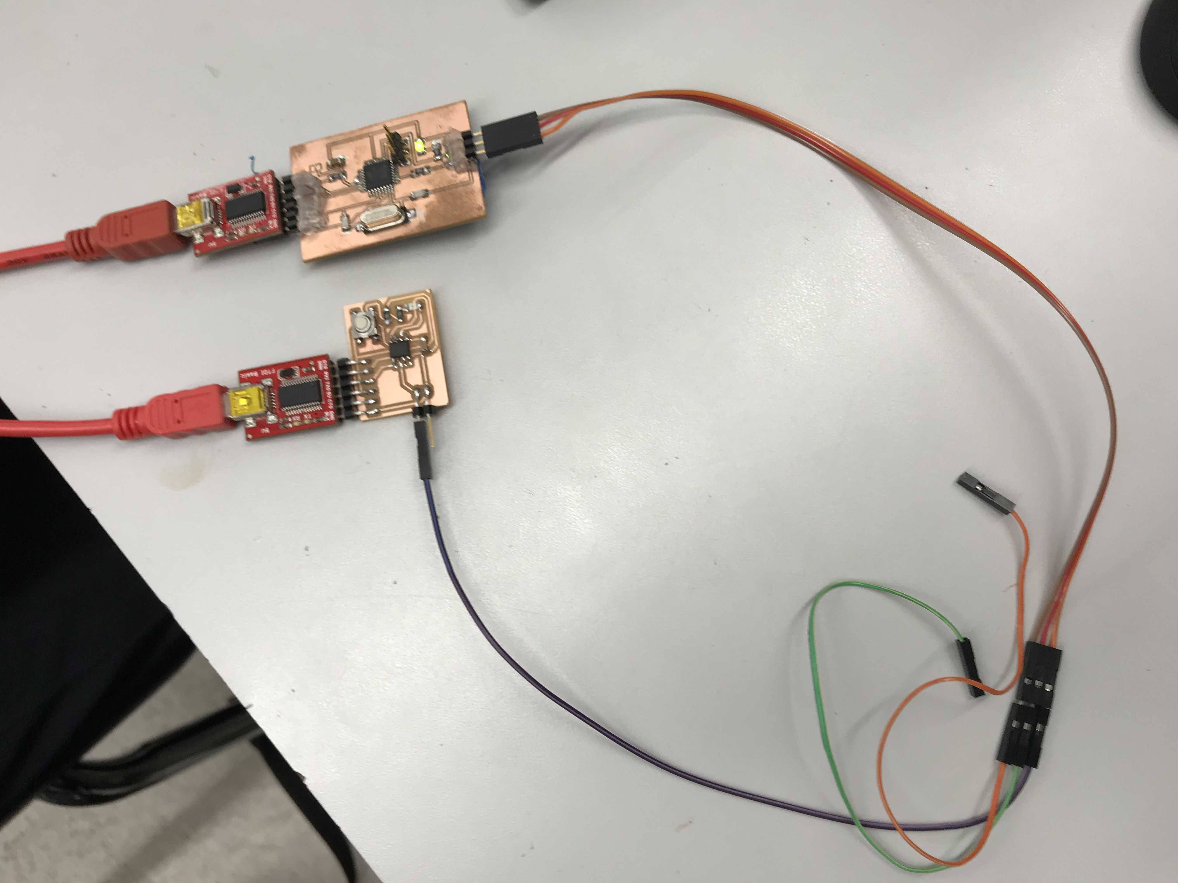
I soldered on all the required components: - 1x ATTiny45 Chip - 1x Omeron Tactile Switch - 1x 6 Pin Right Angle Male Header - 1x 2 Pin Right Angle Male Header - 1x 1 uF Capacitor - 1x 10k Ohm Resistor - 1x 1k Ohm Resistor
Here is what the finished board looks like:
After uploading the blink code to it, the LED stayed on and when I clicked the button, it turned off.
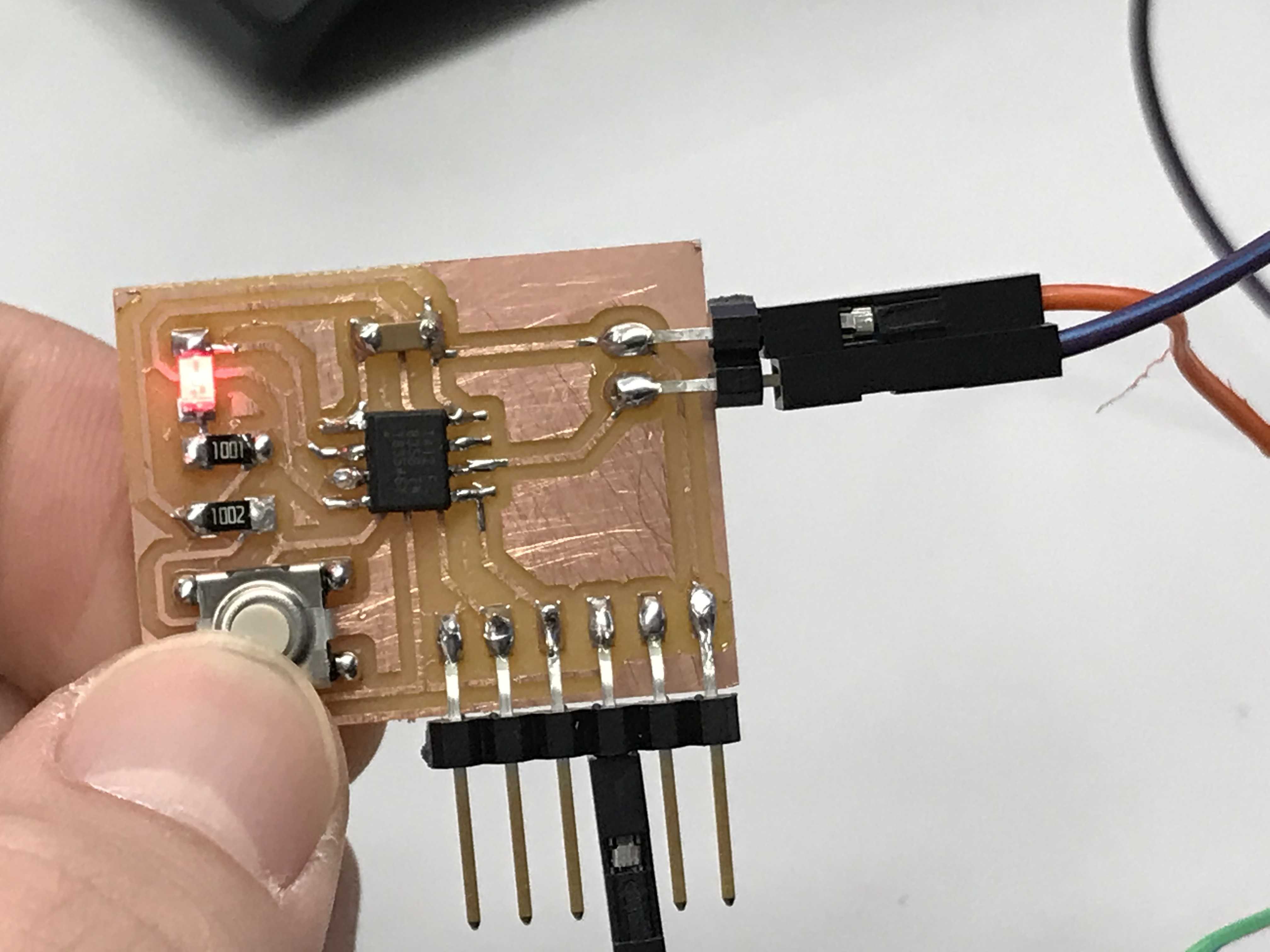
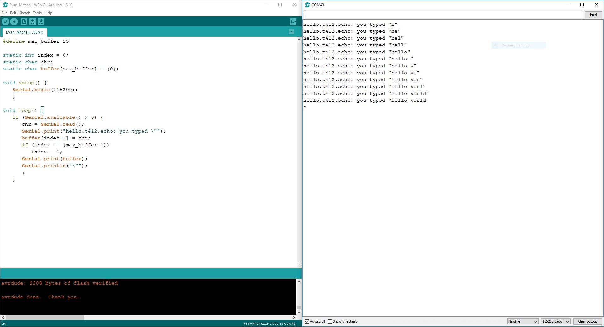
The echo code on the other hand worked flawlessly. Entering “hello world” through serial communication echoed the message back to me.
Here are the files for this week: board schematic
Group Assignment
The group assignment can be found here.