5. Electronics production
This week’s assignment was:
group assignment:
      characterize the design rules for your PCB production process
   individual assignment:
      make an in-circuit programmer by milling and stuffing the PCB,
      test it, then optionally try other PCB processes
Creating the G-code
I first downloaded these two images from this guide:
I used Fab Mods to convert these two images into gcode.
First, by right clicking, you bring up a menu. In this menu there are four options:
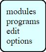
Click “programs” to bring up a list of options.
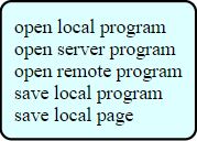
Click “open server program” to bring up a list of previously created programs that you can access.
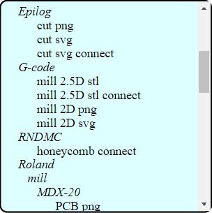
Under machines > G-code you want to click “mill 2D png” to bring up the program to convert PNG to G-code.
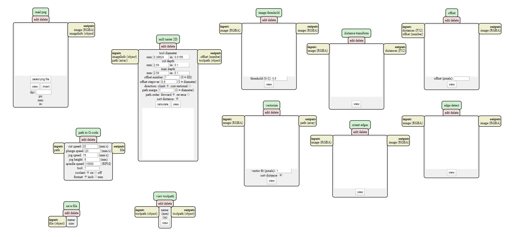
There are four modules that should be paid the most attention to. First is the “read png” module:
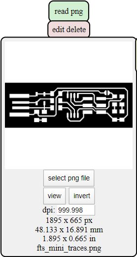
Insert your picture by pressing the “select png file” button.
Next, you need to look at the “mill raster 2D” module.
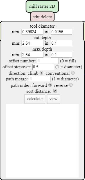
In here, you set the parameters for milling. Specifically what you need to set is the diameter of your tool, the cut depth (how far the tool goes down on each pass), and the max depth (the depth to where you want the mill to cut to). For cutting out the outline, the max depth should be the width of the material and the cut depth should be set where the mill needs 6-8 passes to fully cut out the material. For traces, both the max depth and cut depth should be set to where the bit does not go too far into the board but still cuts the traces.
The offset number should be changed to the appropriate number (0 = fill, 1 = no fill).
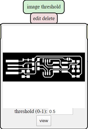
On the image threshold module, the threshold parameter decides how sensitive the program picks up black and white in your png image. This should be set to almost 1 for the outline cut as the border is hard to pick up.
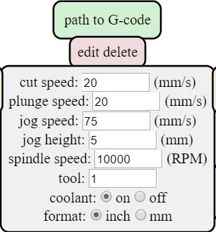
Lastly is path to G-code where you set the speed of your bit. It is important that these are set correctly so as to not break your bit. The correct settings for bantam tools can be found on their website:
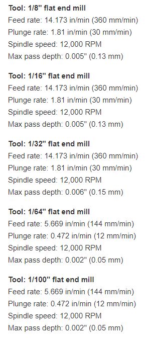
Fill in the same settings into the path to G-code module and set the jog speed to the same as the cut speed. It is important to know that the Othermill V2 takes in these values as mm/minute but in this module, it says it is input as mm/s. Fab Mods does not know if you are using an Othermill or not so put in your values as mm/minute. In addition, change the format to mm from inches.
To get the actual G-code file, go back to the mill raster 2D module and click calculate to download your file.
I did this for both images to create the two G-codes I needed to cut out my programmer. One major thing with the G-code is that it has one line of code that is not compatible with the Othermill. There will be a line that has “G54” and this will break the z axis of your G-code. Change this to “G55” to fix this problem.
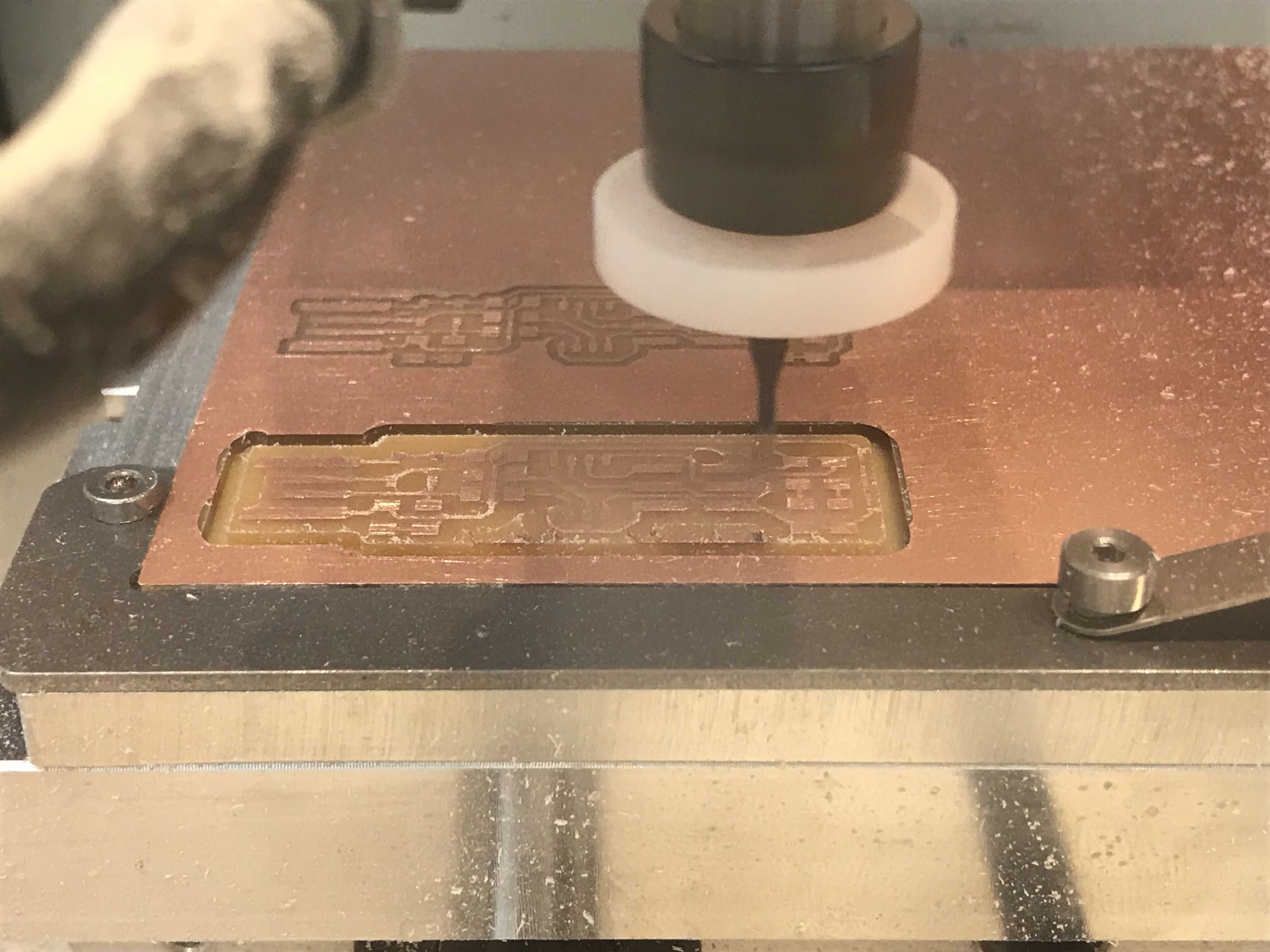
Milling the PCB
The milling machine I used was the Othermill Pro. The software I used was the Bantam Tools Desktop Milling Machine Software.
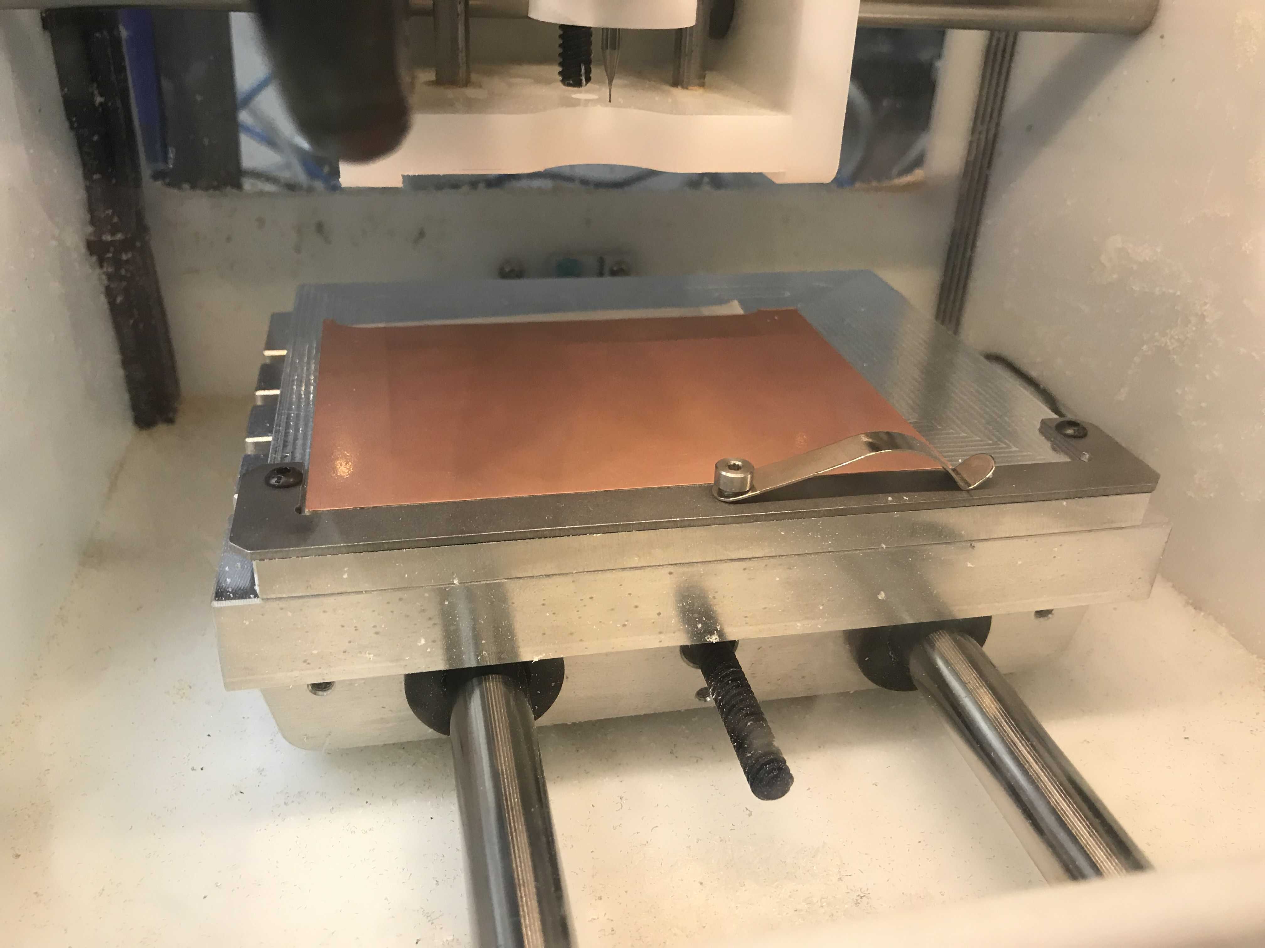
The material I cut my programmer out of was a single-sided FR-1. Enough pieces of nitto tape to cover the entire backside was applied to the material and the length/width was measured using calipers.
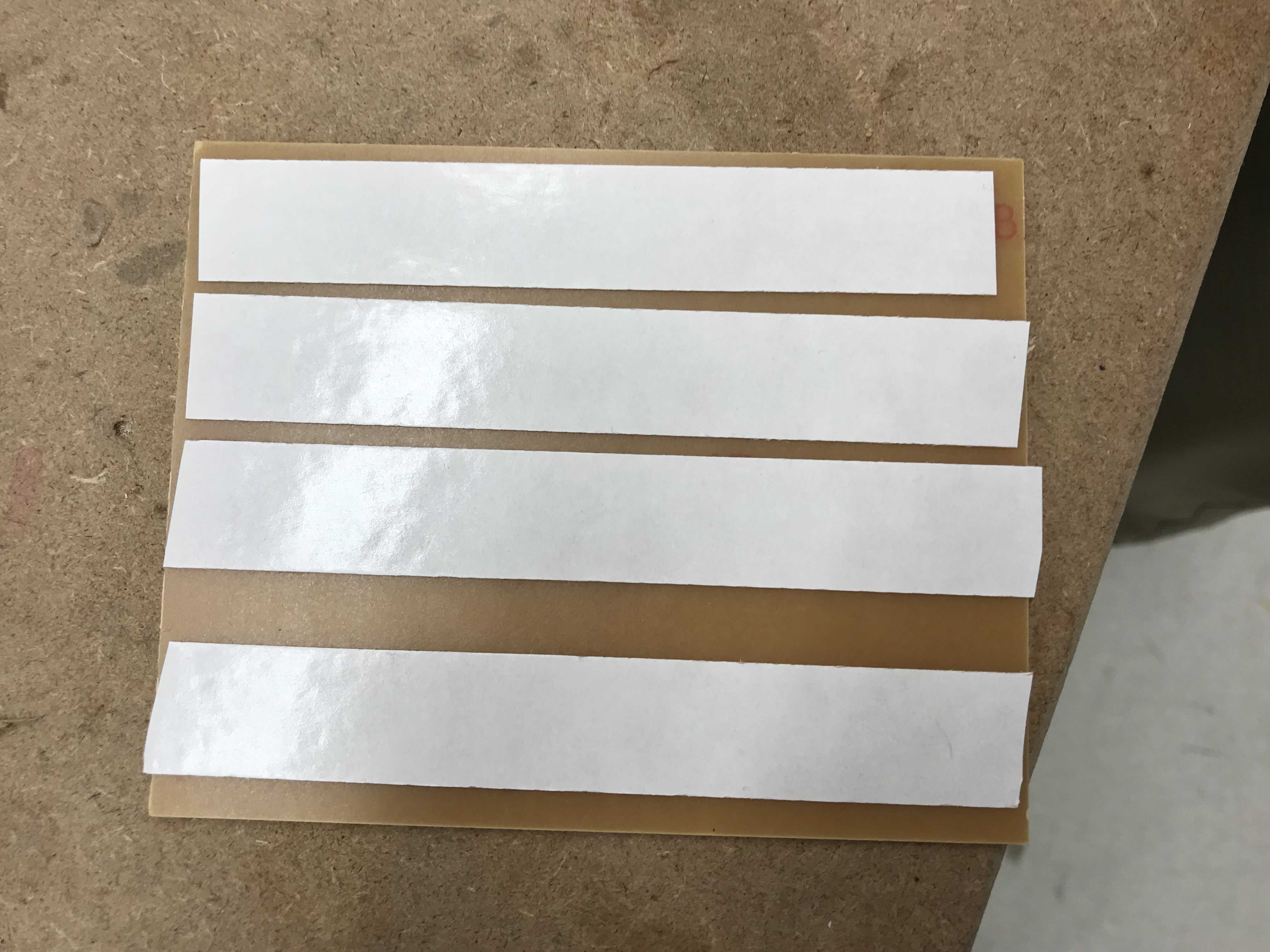
I placed the material into the milling machine and set all the parameters (material type, length, and width) for milling in Bantam Tools. The height of the FR-1 was acquired using the Probe Material Thickness within the BitBreaker option in the software.
I imported my G-code and moved both the outline cutout along with the traces to an area that was fully within the milling area by setting the x and y both to 4 millimeters.
I inserted my 1/64th inch bit into the mill as I wanted to cut out my traces first and hid the gcode for milling with the 1/16 inch bit.
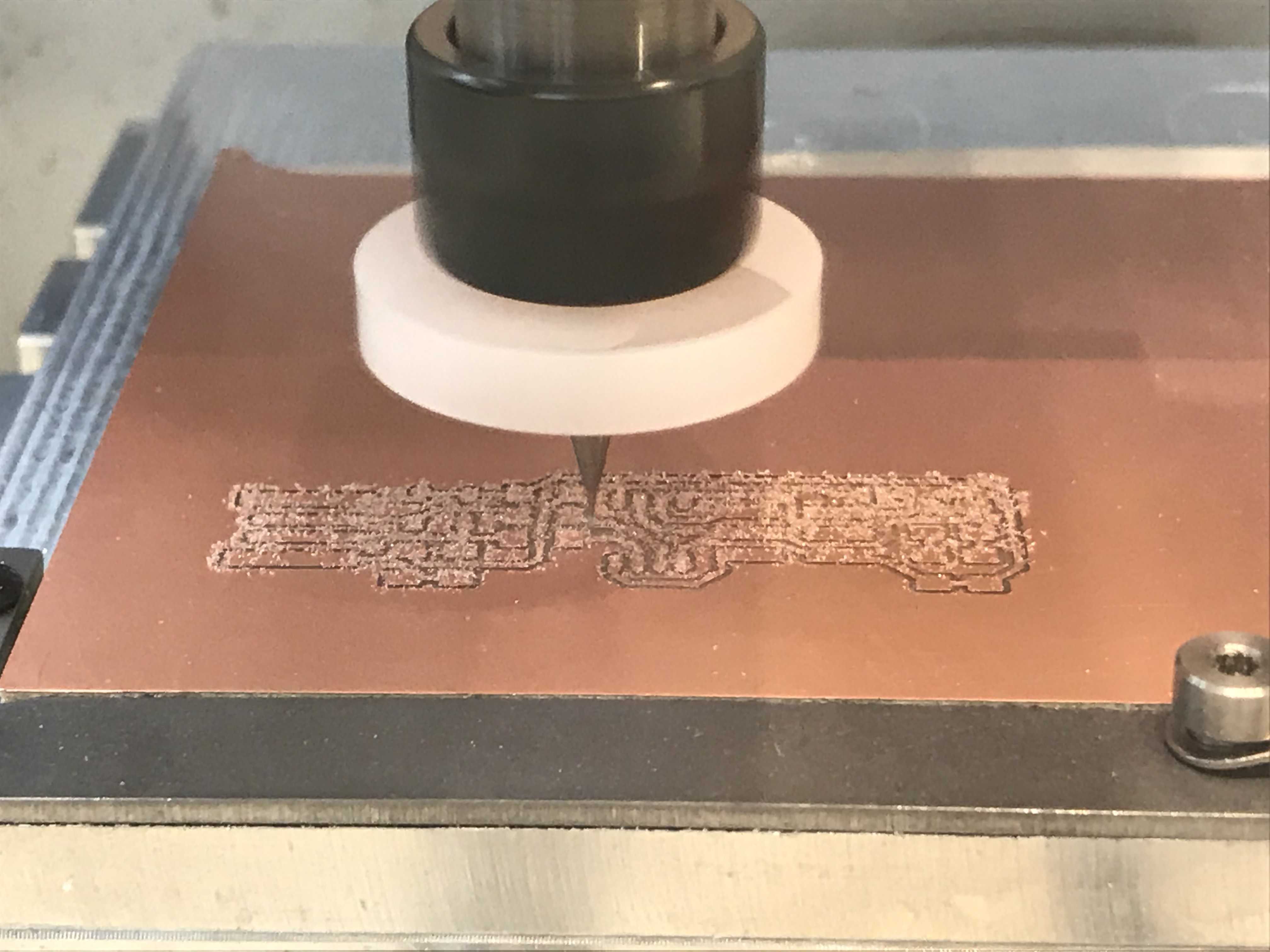
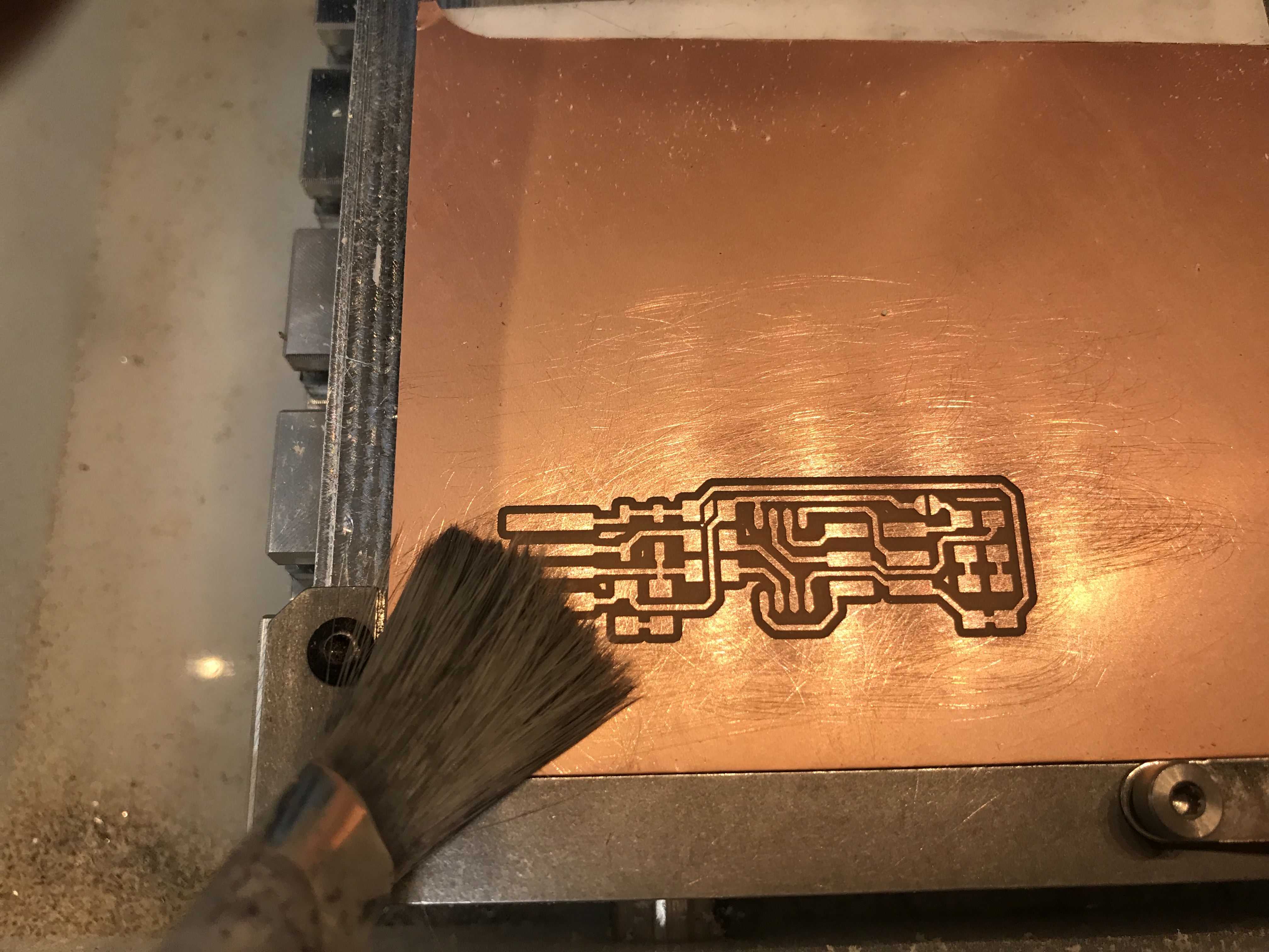
To fully cut out the programmer, I replaced the 1/64th bit with a 1/16th inch and milled the outline code.
After each cut, it is good practice to sweep away any particles using a brush and sand any metal burrs on the traces.
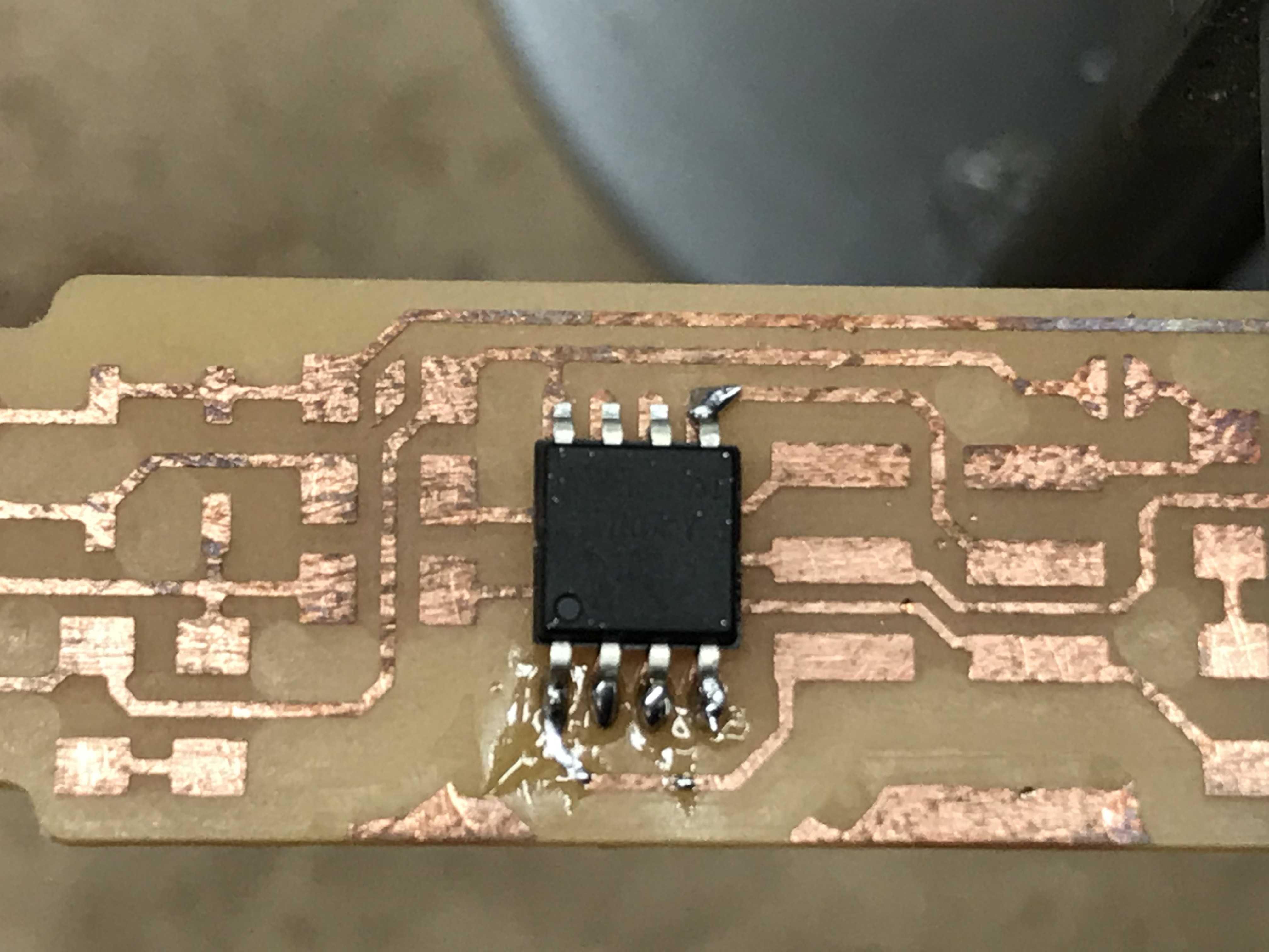
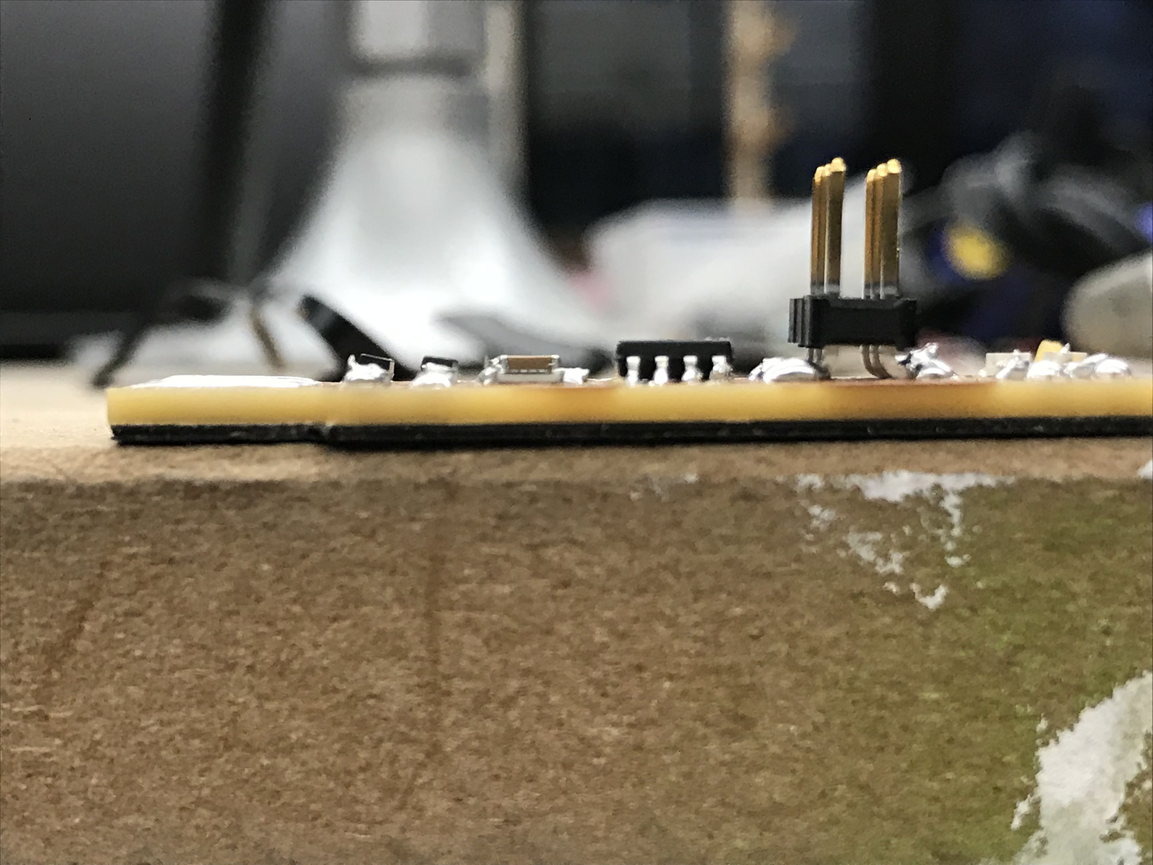
Soldering the Components
To make surface mount soldering a bit easier, it might help to use a soldering iron with a very fine tip.
Now, I soldered the programmer from the inside-out starting with the ATtiny45 and going outward.
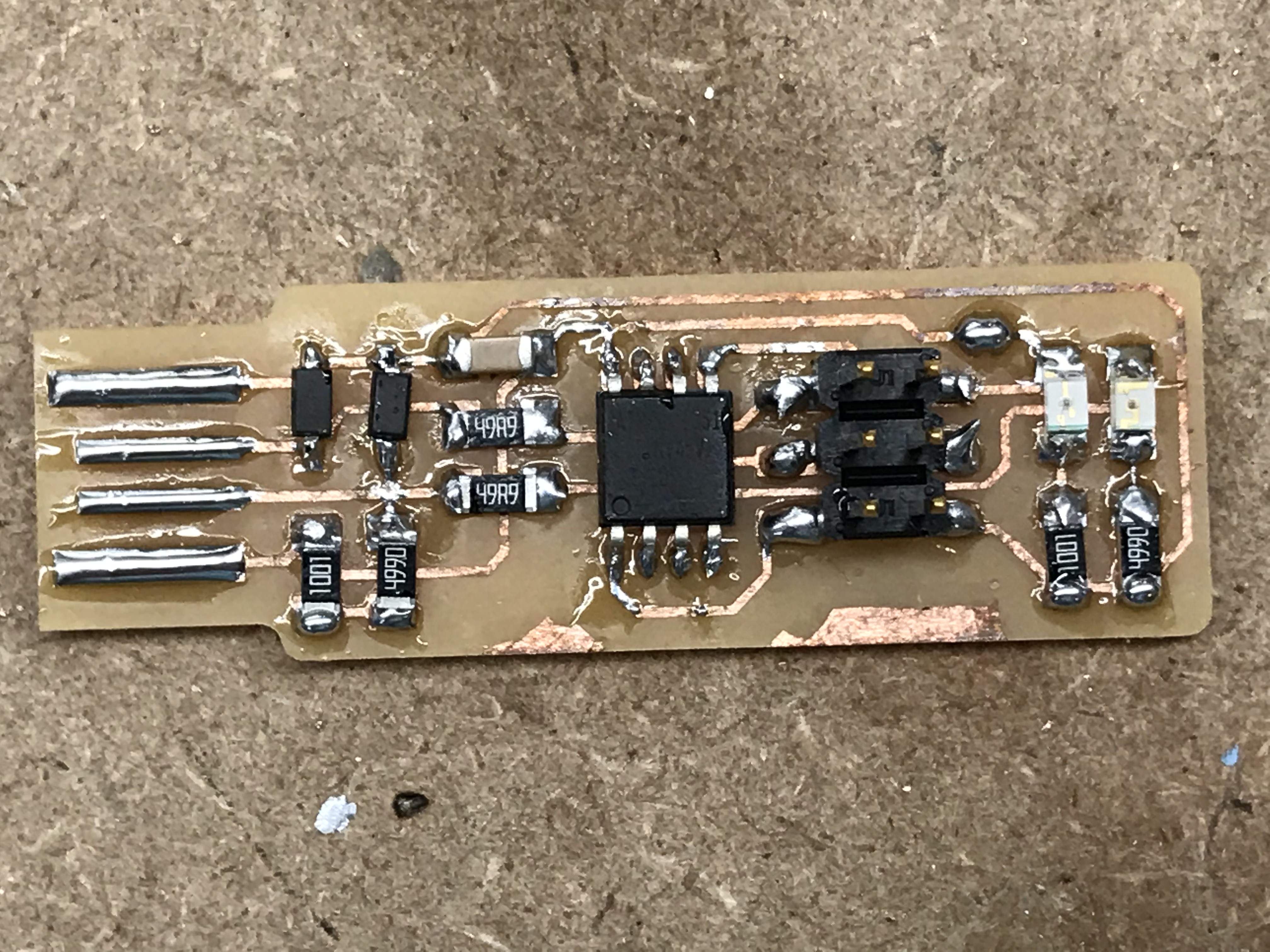
Correct wiring for the board was procured from this guide.
Remember that every component has a correct orientation except for the capacitor and it is important to check constantly for mistakes.
Once the board is finished, you can 3D print a case for it or simply apply tape to the bottom to increase the thickness to where it can tightly fit into a USB port.
Programming the Programmer
Now that all my pins are soldered onto my board, it is time to program the programmer. I followed this very helpful guide through the entire process.
Since I was using Windows, additional steps were required to program my ATTiny 45 Chip. Three files needed to be downloaded and extracted first:
-
Grab the latest version and extract this file to
C:/Program Files. -
Simply run the exectuable and and extract to the default location listed in the installer.
-
Once the archive file is downloaded, extract this folder to
C:/Program Files.
Update Your Path
Search for “Path” in the Windows search bar and “Edit the system environment variables” should pop up.
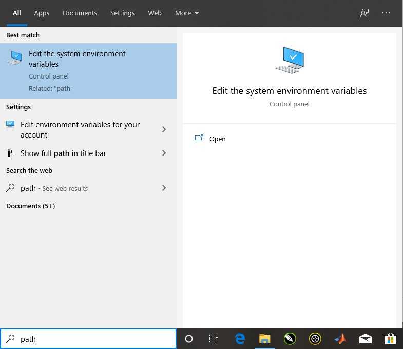
Open this to arrive at the Advanced tab in System Properties. Select Environment Variables at the bottom of the window to edit your Environment Variables.
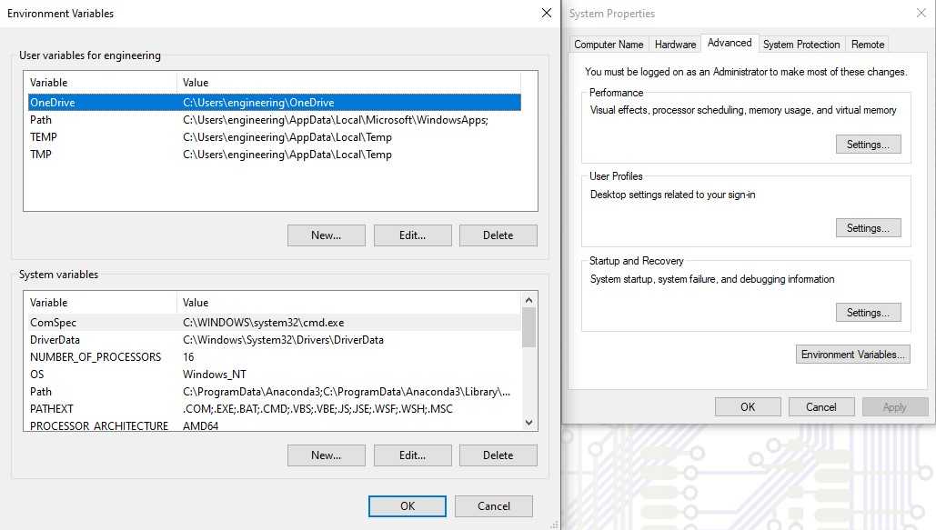
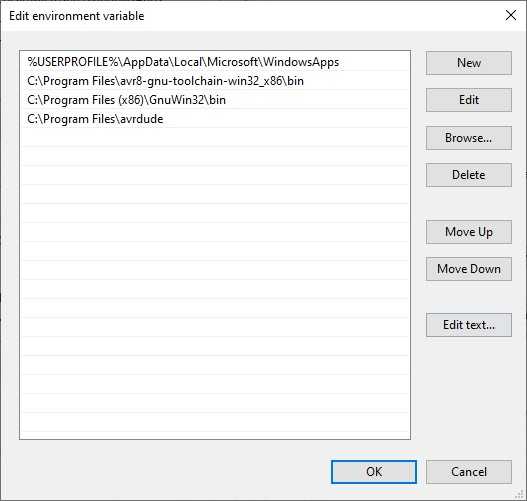
Enter Path in the User variables and add three new environment variables.
- C:/Program Files (x86)/GnuWin32/bin
- C:/Program Files/avrdude
- C:/Program Files/avr8-gnu-toolchain-win32_x86/bin
- This will most likely not be the same path that you will use. The path that goes here should be
C:/Program Files/+ (Your AVR Toolchain File Name) +/bin. In my case, the name of the file wasavr8-gnu-toolchain-win32_x86/bin
Installing Drivers
Install Zadig to install the USB drivers needed to recognize a FabTinyISP.
Plug an already programmed FabTinyISP into your computer.
Open Zadig, select the Options drodown, and enable List All Devices.
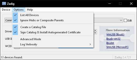
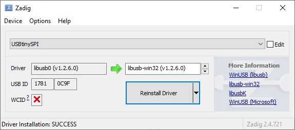
In the main dropdown box to list all the USB devices, a device named USBtinySPI.
In the driver selection box, use the arrows to navigate through all the drivers until the libusb-win32 driver is selected. You only need this driver once and do not need to install it again for consecutive programmer uses.
Programming the ATtiny45
Download the firmware source code and extract.
The extracted folder should contain another similarly named folder with four files inside. Copy the system path of this folder and open up Windows Powershell. Enter:
cd <YOUR_FILE_PATH_GOES_HERE>
Now, type make all to build the Makefile. This command should populate the firmware source code folder with a few more files.
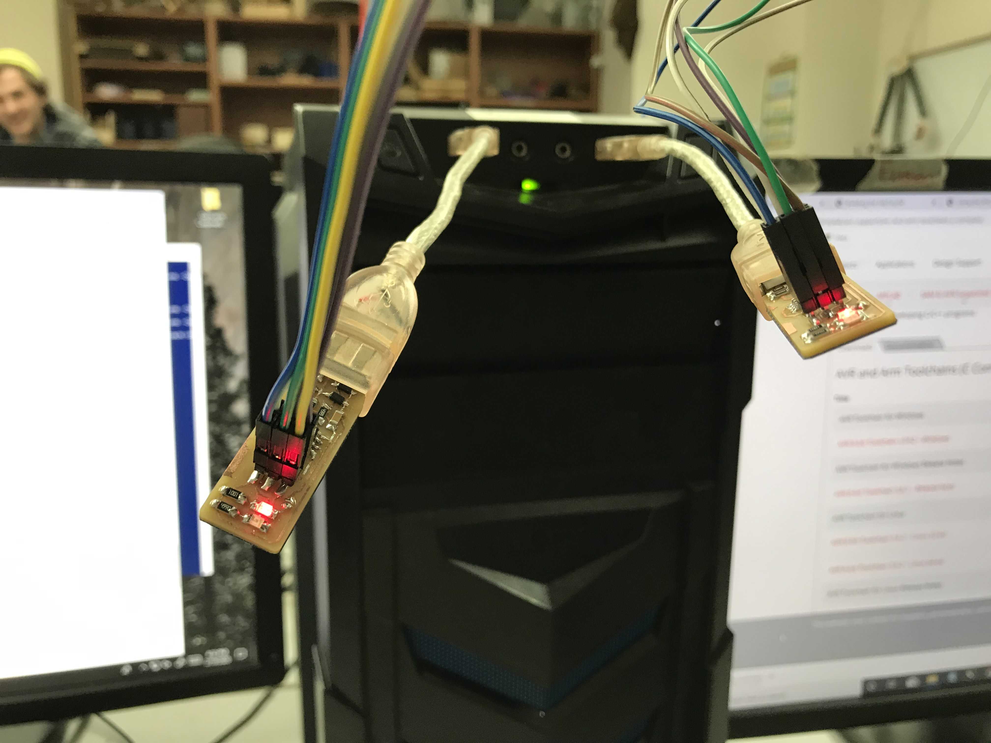
Connect what you are trying to program to your programmer using the six pins. Make sure the pins are lined up and that power is supplied via the six pin or a USB connection. If you are using a USB connection, do not connect your programmer directly into yur computer’s USB port as this may damage the port.
Run the following commands next:
make flash
make fuses
make rstdisbl
Now that your programmer is fully programmed, be sure to break the solder bridge.
Even after all this, your programmer still may not work. It is good to test to see whether your programmer can actually program other things. Trying making another programmer or program an Arduino to do something in order that you see if everything works.
Group Project
The group project is here.
I updated the website and helped fellow peers understand how to use Fab Mods.