9. Embedded programming
individual assignment:
      read a microcontroller data sheet
      program your board to do something,
         with as many different programming languages
         and programming environments as possible
   group assignment:
      compare the performance and development workflows
         for other architectures
Programming the Board
We used the programming software, jtag2updi, to upload code into our boards that we made for the Elecronics Design week. To use it, we created a board with an ATMega 328p chip on it to be used with jtag2updi. The board and schematic can be downloaded here: board schematic
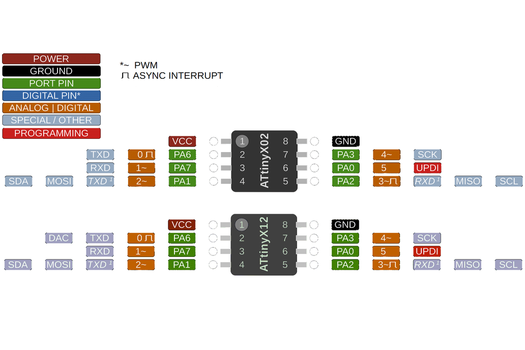
I referenced this pinout diagram for the ATTiny X12 series chips.
Arduino IDE
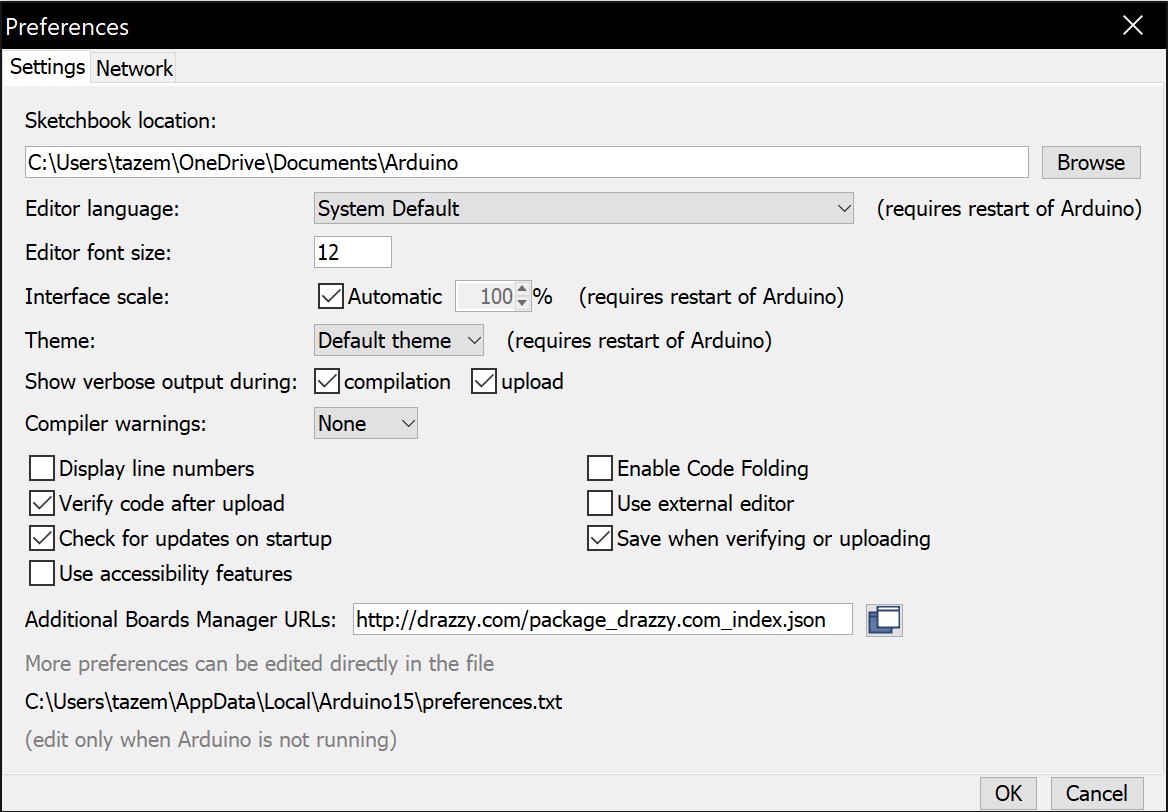
To use the jtag2updi programmer, the megaTinyCore board manager needs to be installed. Adding this link http://drazzy.com/package_drazzy.com_index.json in Additional Boards Manager URLs under Preferences will add the boards to the boards manager. Now under Tools, set your board to the ATTiny412 and the programmer to jtag2updi.
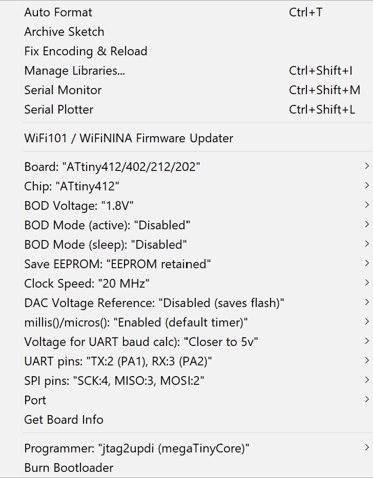
Now, you are ready to use your jtag2updi programmer. Finally, when your code is ready to be uploaded, simply upload your sketch using Upload Using Programmer.
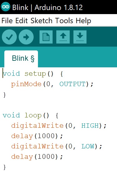
Now for the actual code that I will upload to my board, I first used the example Blink code provided by Arduino. The code does a digitalWrite so the port I referenced in the code were the Analog | Digital pins or the orange color. In this case, it was 0.
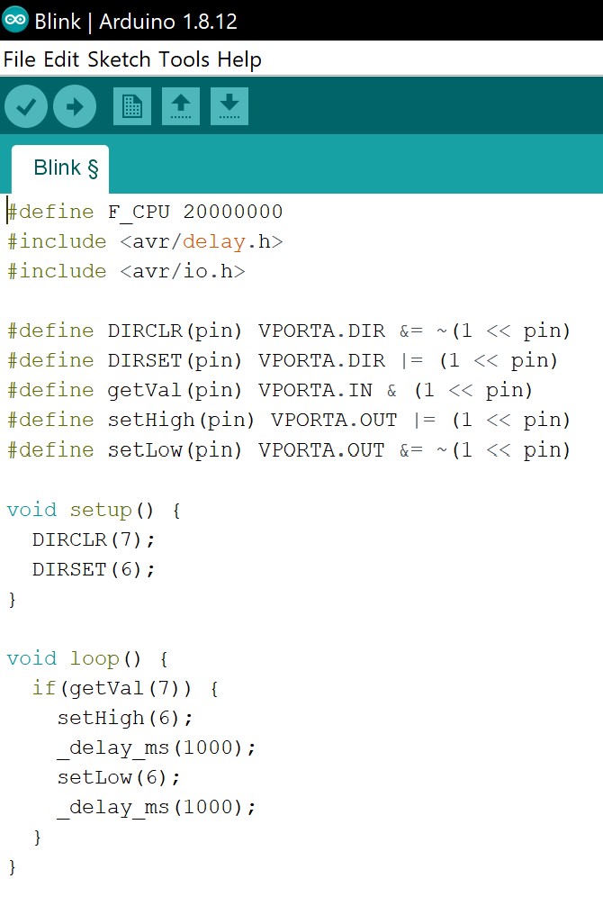
Now it was time to write this in C. I referenced the basic functions data sheet for the ATTiny 412 to better grasp how to manipulate the pins. To setup which ports are input or output, we will change the value of PORT.DIR most preferably with a bitwise operation on these two register: PORT.DIRSET or PORT.DIRSET. The value of ports will be set with a bitwise operation on the virtual port register, VPORT.OUT. The port number we will refer to will be green on the pin out diagram.
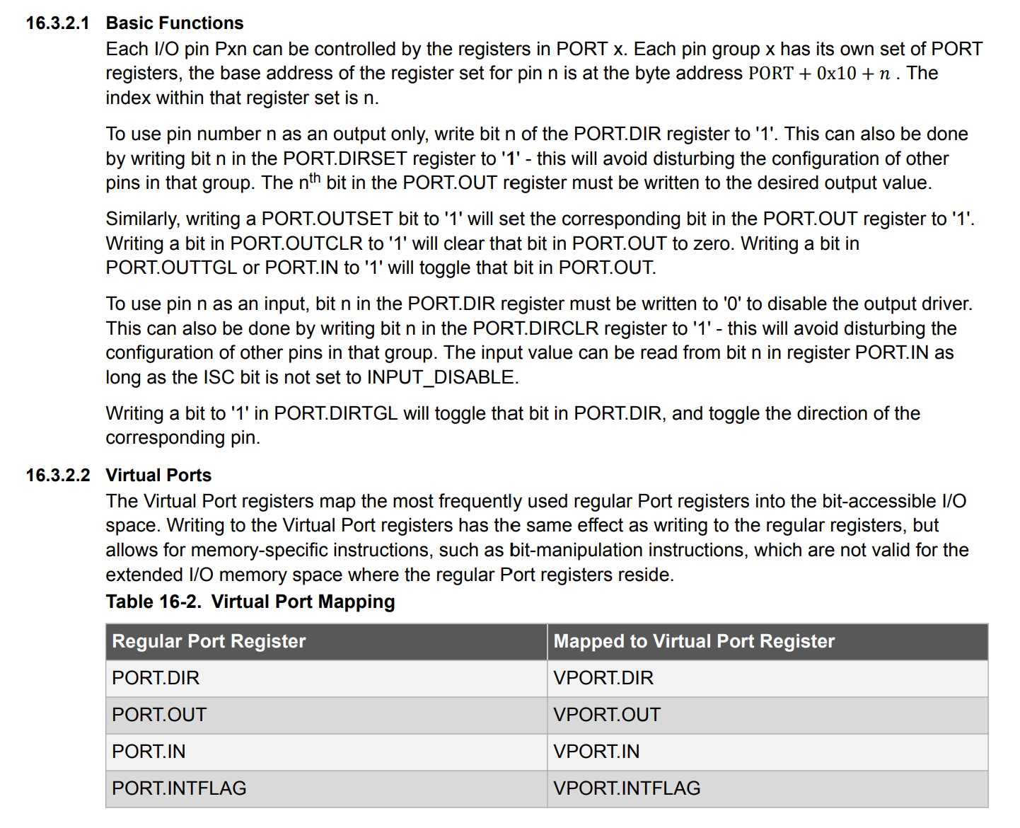
It is alright to write change the regular port register, however, Professor Neil Gershenfeld provides and excellent example of the timings when writing to a port. Writing to the virtual port was the fastest and I chose to implement this into my code.
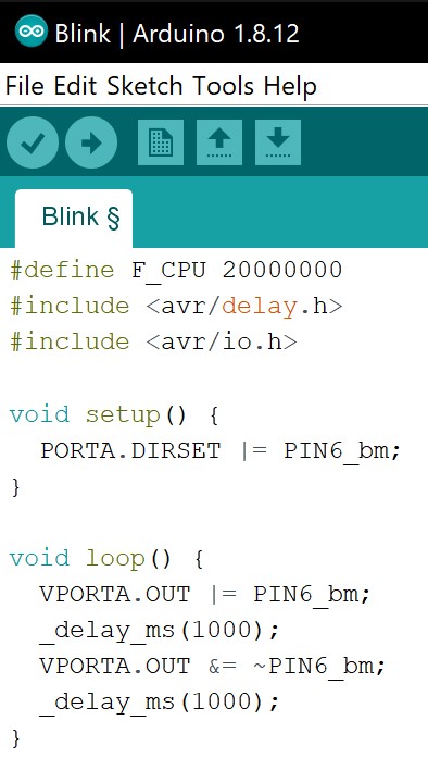
I then tried to created some code to blink only when the button was press down.
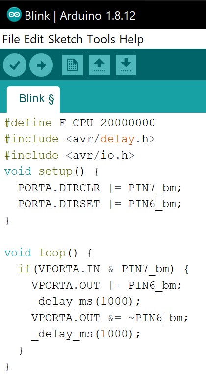
To make it simpler for myself, I defined a few functions that may be used many times.
Atmel Studio 7
To get started, first download Atmel Studio from Microchip. The installation will take quite a while but hang in there. During this installation, I followed this series of YouTube videos by Microchip that guided me through Atmel.
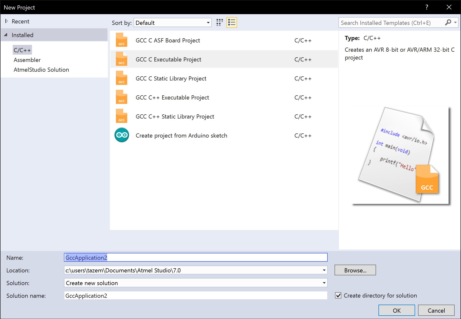
Now in Atmel, create a New Project.

In this case, we will create an Executable Project
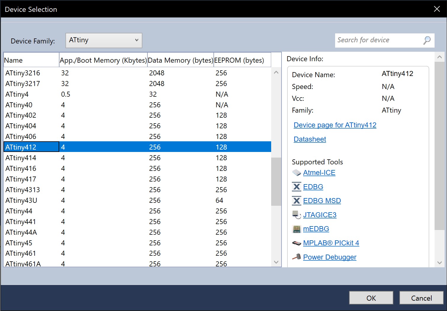
Now for this Executable Project, we will need to specify what chip we are trying to program. In this case, it is an ATTiny412.
Now you should be left on this screen with a bare backbone main.c file.
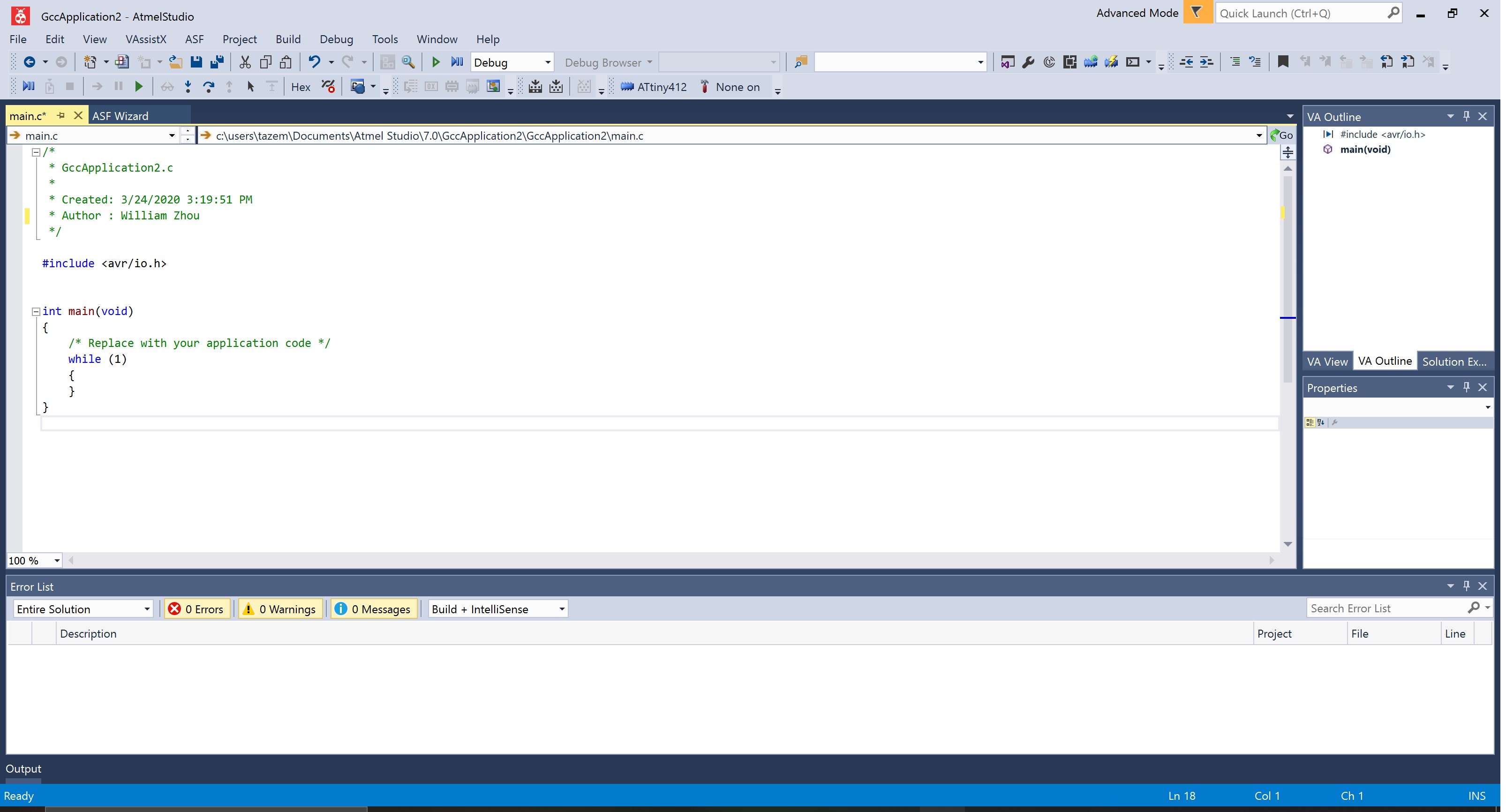
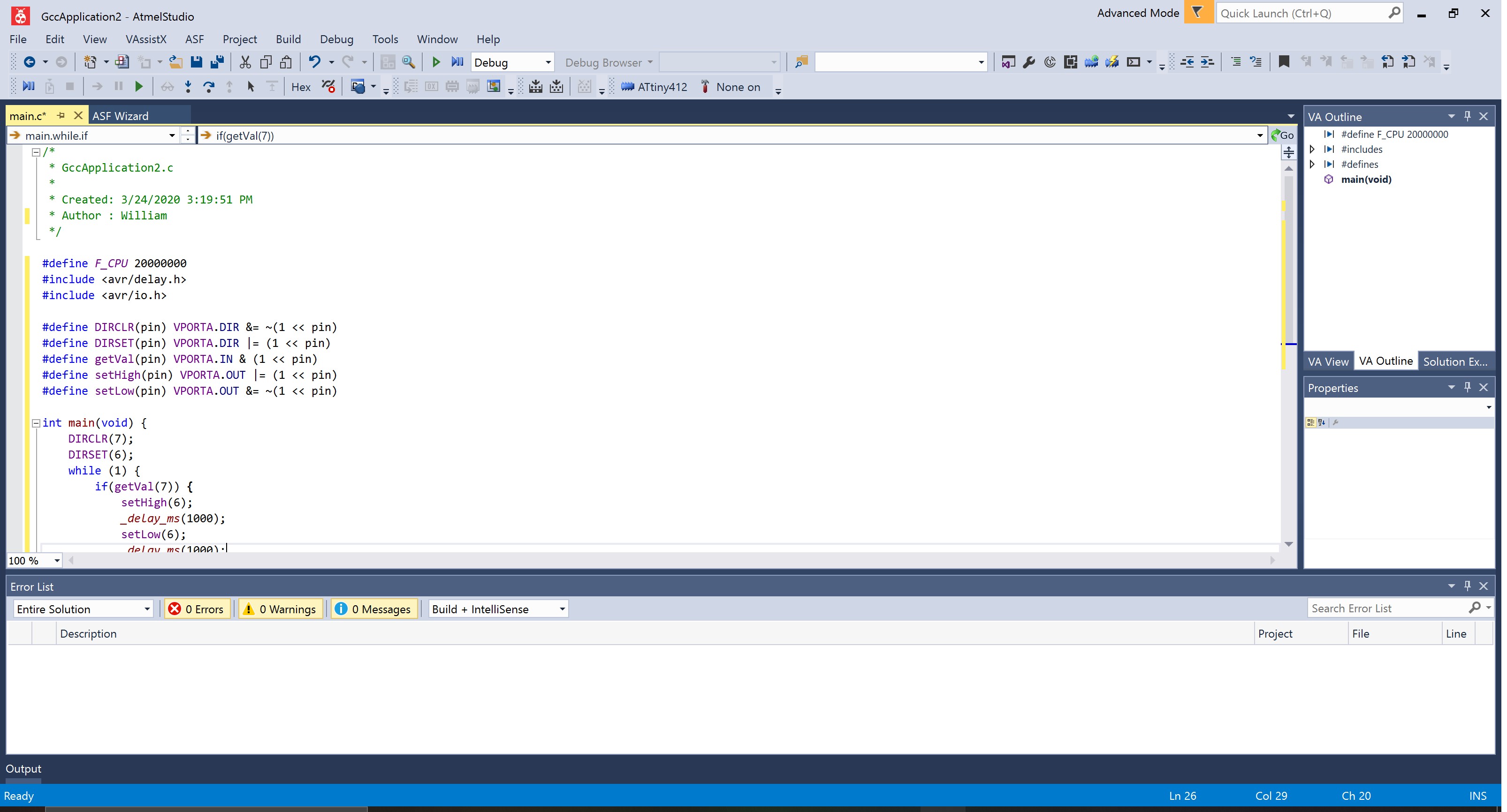
Simply put the code you want to upload into the ATTiny412 chip into this file.
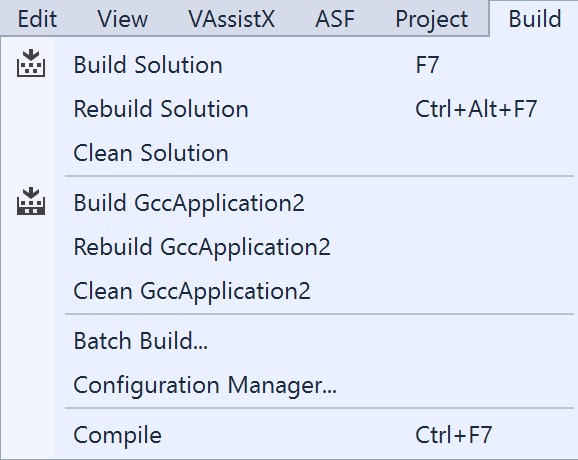
Once this is ready, you will need to go under Build and build your project. If you change your code later, you will need to use the rebuild option.
Now, it is time to set up the jtag2updi as a programmer that uses avrdude. I followed this guide to set it up; however, I modified it a bit as it didn’t quite work.
First, navigate to the avrdude.exe that Arduino uses. This will mostly likely be in your Documents folder at *\Documents\ArduinoData\packages\arduino\tools\avrdude\6.3.0-arduino17\bin\avrdude.exe
You will also need the avrdude.conf file that came with the megaTinyCore board manager you installed earlier. You will find this in *\Documents\ArduinoData\packages\megaTinyCore\hardware\megaavr\1.1.5\avrdude.conf
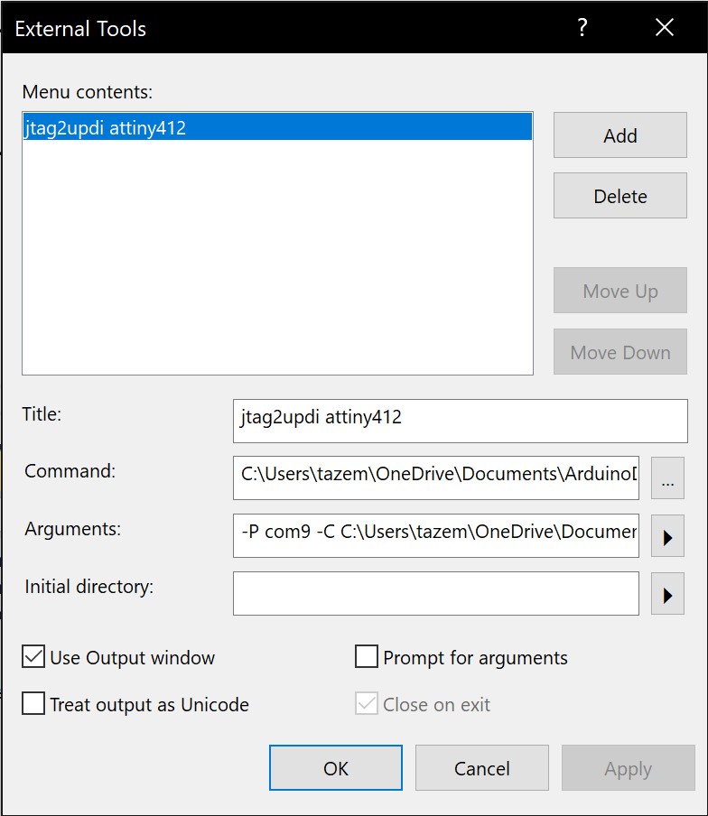
Now open up External Tools under the Tools tab. You will enter the path of avrdude.exe from Arduino into the Command box. Now what you will need to enter into the Arguments box will follow these guidelines. Enter each each line into the Arguments box with just a space in between
-P com9                                            # The port your jtag2updi is plugged in
-C (PATH)                                          # The path of your avrdude.conf file
-c jtag2updi                                       # The programmer you are using
-p t412                                            # The chip you are trying to program
-U flash:w:$(ProjectDir)Debug/$(TargetName).hex:i  # Memory operation specification (Don't Change)
Once you are finished, it should look something like this:
-P com9 -C C:\Users\tazem\OneDrive\Documents\ArduinoData\packages\megaTinyCore\hardware\megaavr\1.1.5\avrdude.conf -c jtag2updi -p t412 -U flash:w:$(ProjectDir)Debug\$(TargetName).hex:i
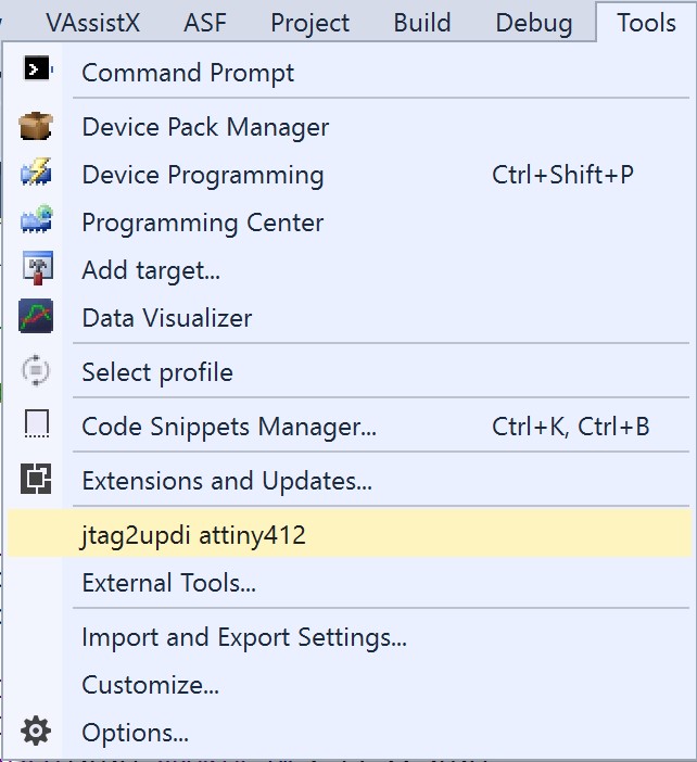
When you are ready to upload your C code to the ATTiny412 chip, simply click on the Tool you just created and the code will be uploaded.
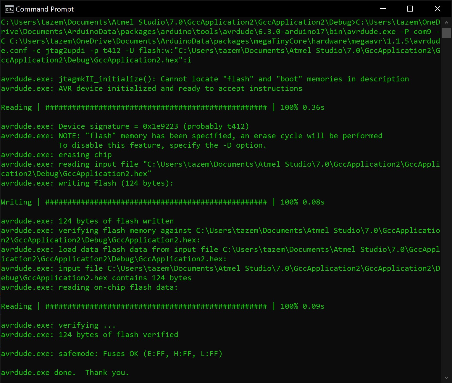
Command Prompt/Powershell
If you really wanted to, you could locate the hex file that Atmel Studio builds for you and use command line to upload to the MCU.
Simply join what is in the Command box and Arguments box to create one large string. Modify the memory operation specification so that where it says “$(ProjectDir)Debug/$(TargetName).hex” is replaced with the actual path of your hex file.
Here are the files for this week: download
Group Project
The group assignment can be found here.