4. Computer controlled cutting
This week I worked on cutting something on the vinyl cutter and designing, lasercutting, and documenting a parametric construction kit. In addition as a group, we characterized our lasercutter’s focus, power, speed, rate, kerf, and join clearance.
Vinyl Cutting
Using the vinyl cutter, I created a sticker that would eventually be displayed on the window of our instructer’s office. My original idea was to create a sticker that was 3D where I would layer multiple stickers on top of each other. The shape would a be a pyramid with tabs that would allow the pyramid to hang off the wall and stand upright.
I used a sketch in fusion 360 to create each layer of my pyramid. I knew that each layer would have a very small height so I would need a good amount of layers to actually have a pyramid. I started with 27 layers where the largest layer would be 1 inch by 1 inch and each subsequent layer would decrease by roughly 0.046 on each side.
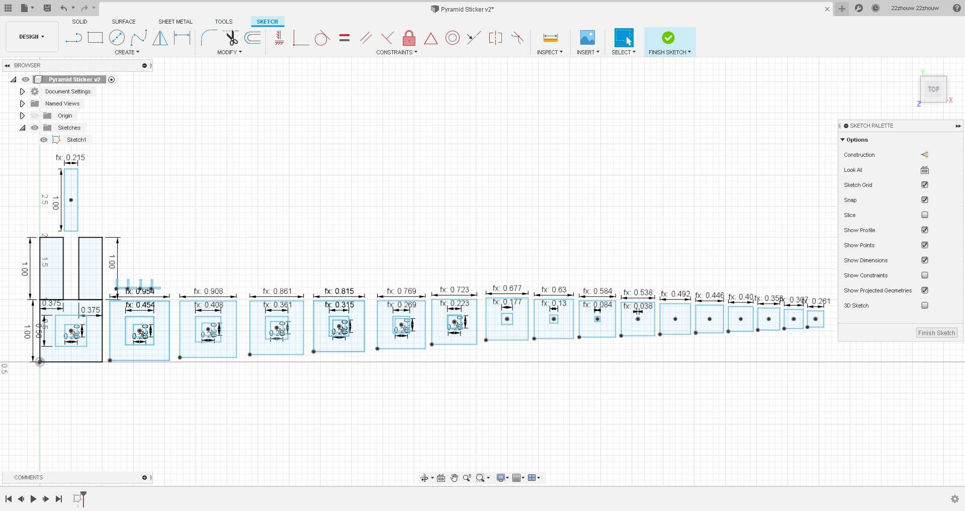
Once I had this sketch, I exported it as a dxf file and imported it into CorelDraw to realign the layers to fit onto the sillhouette. Once I was finished, I exported it as an svg file and sent it to Silhouette Studio.
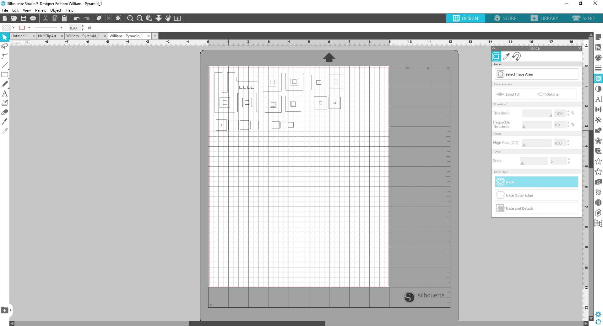
In Silhouette Studio, you need to trace the parts of your file that you want to cut on the vinylcutter. To do so, I used the trace area tool.
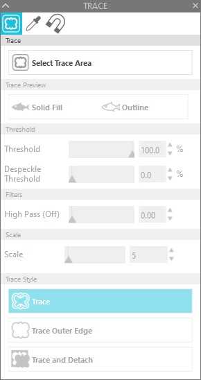
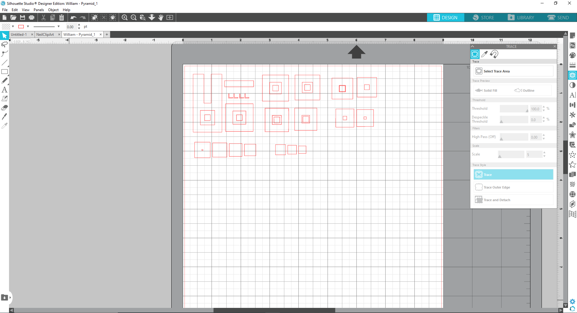
I previewed the trace with outline and then maxed out the tresholds so that it could pick up every line in my svg file. The red outline it creates is now what the vinylcutter will cut out on the piece of vinyl you insert.
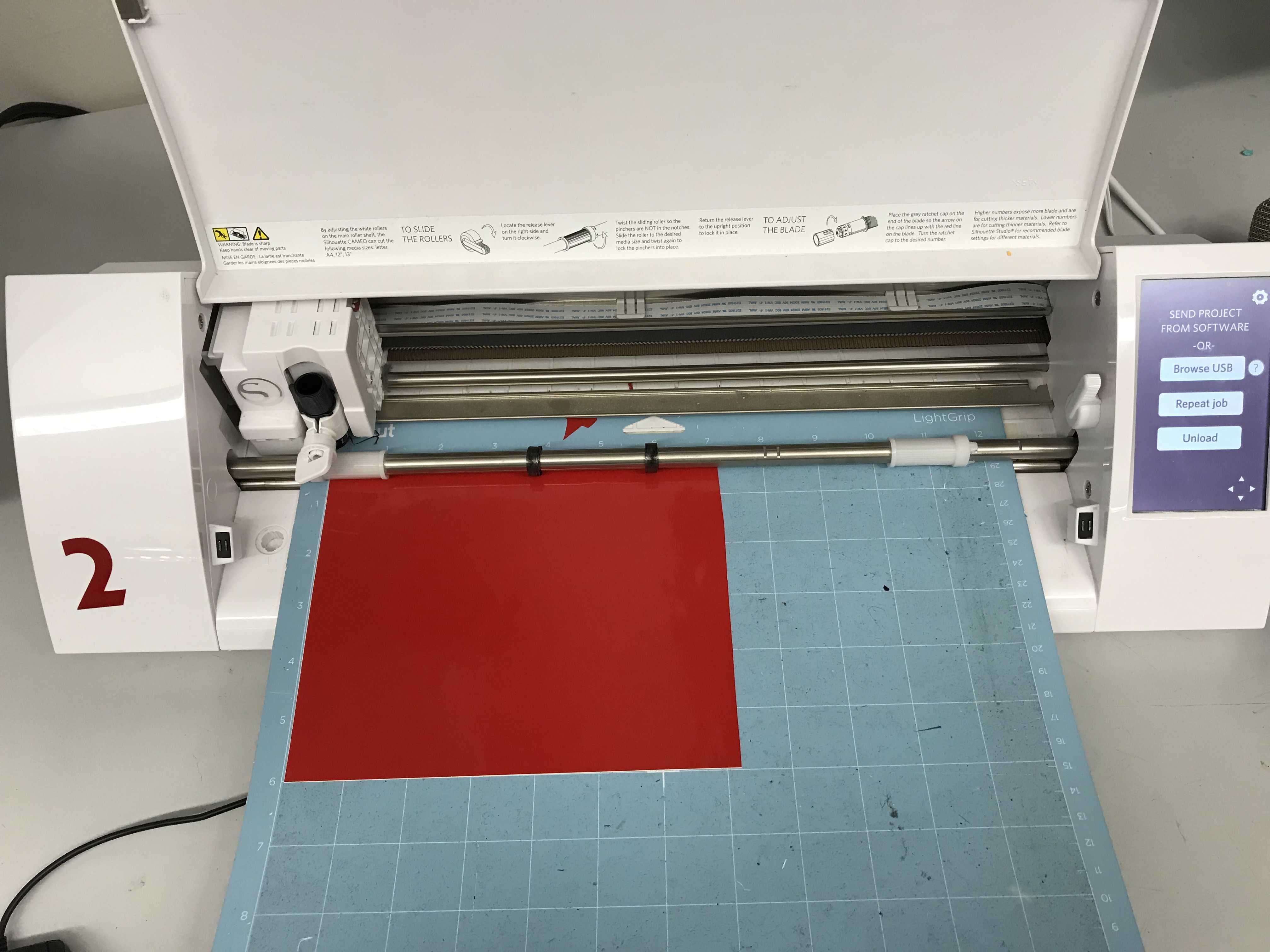
I loaded a piece of vinyl onto a cutting mat and inserted it into the vinyl cutter.
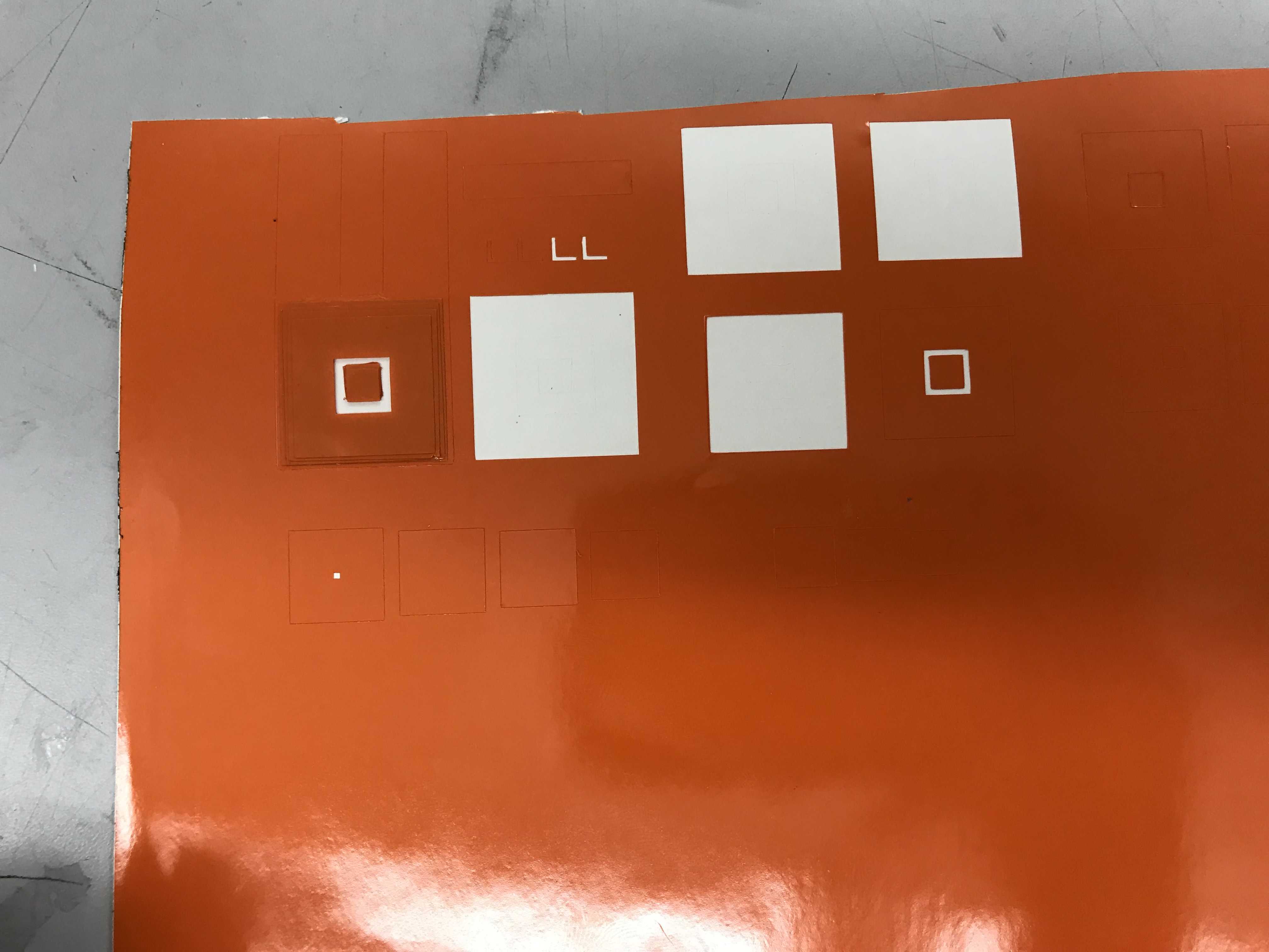
Looking back, I should have used some alignment markers on my sticker to help facilicate putting the layers on my pyramid. Instead, I painstakingly put each layer onto my base layer and lined it up with vision.
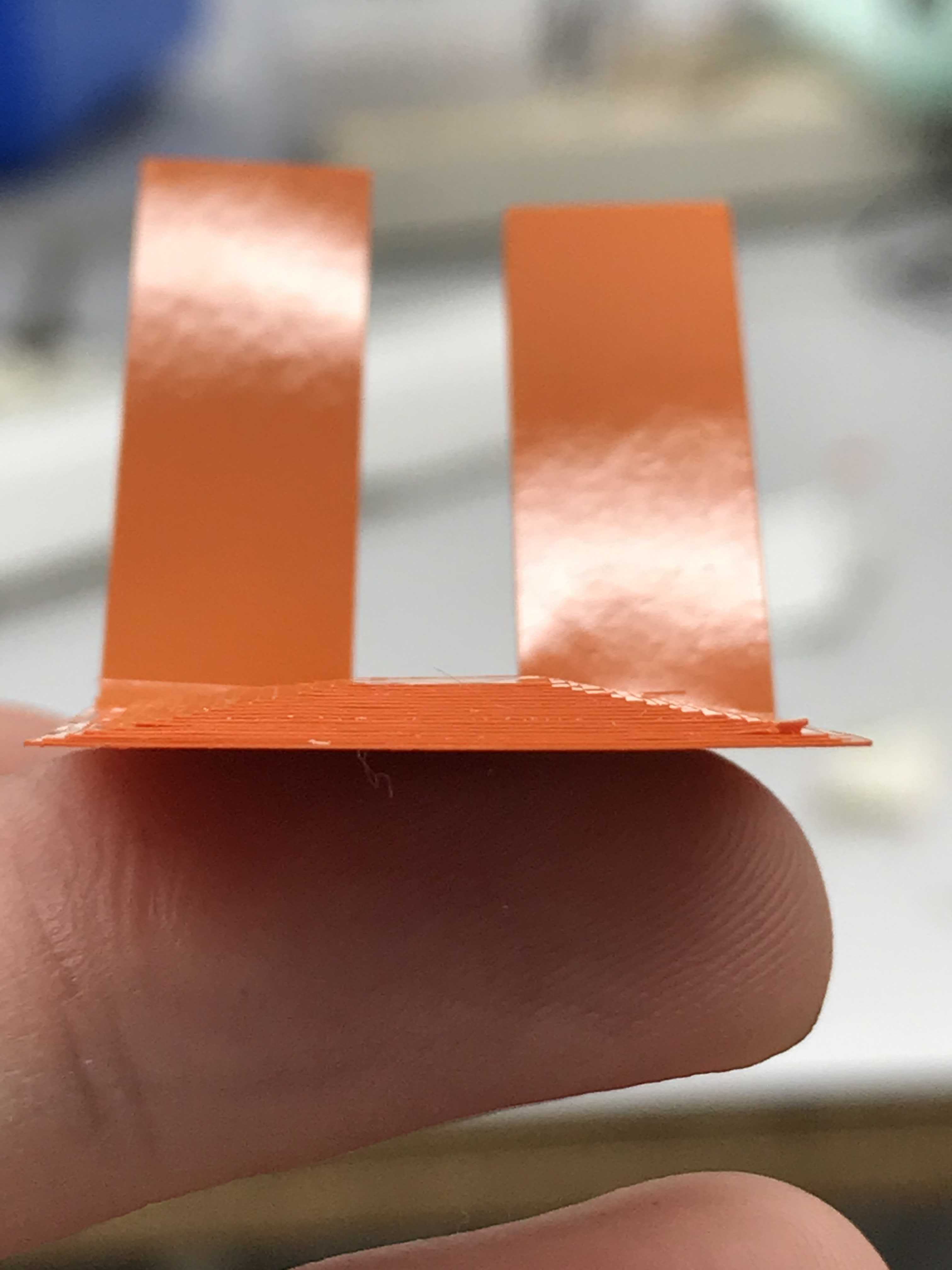
The end result definitely wasn’t what I wanted it to be. I will make another sticker but a conventional 2D one.
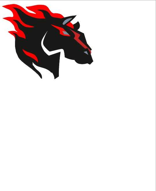
This time I used an svg file of an icon and modified it to make it a little easier to see.
I started with the original image of the icon:

and set all the white on the svg to red so that I could see and manipulate it easier.

After this, I removed all the unncessary background and removed parts of the border around the icon.
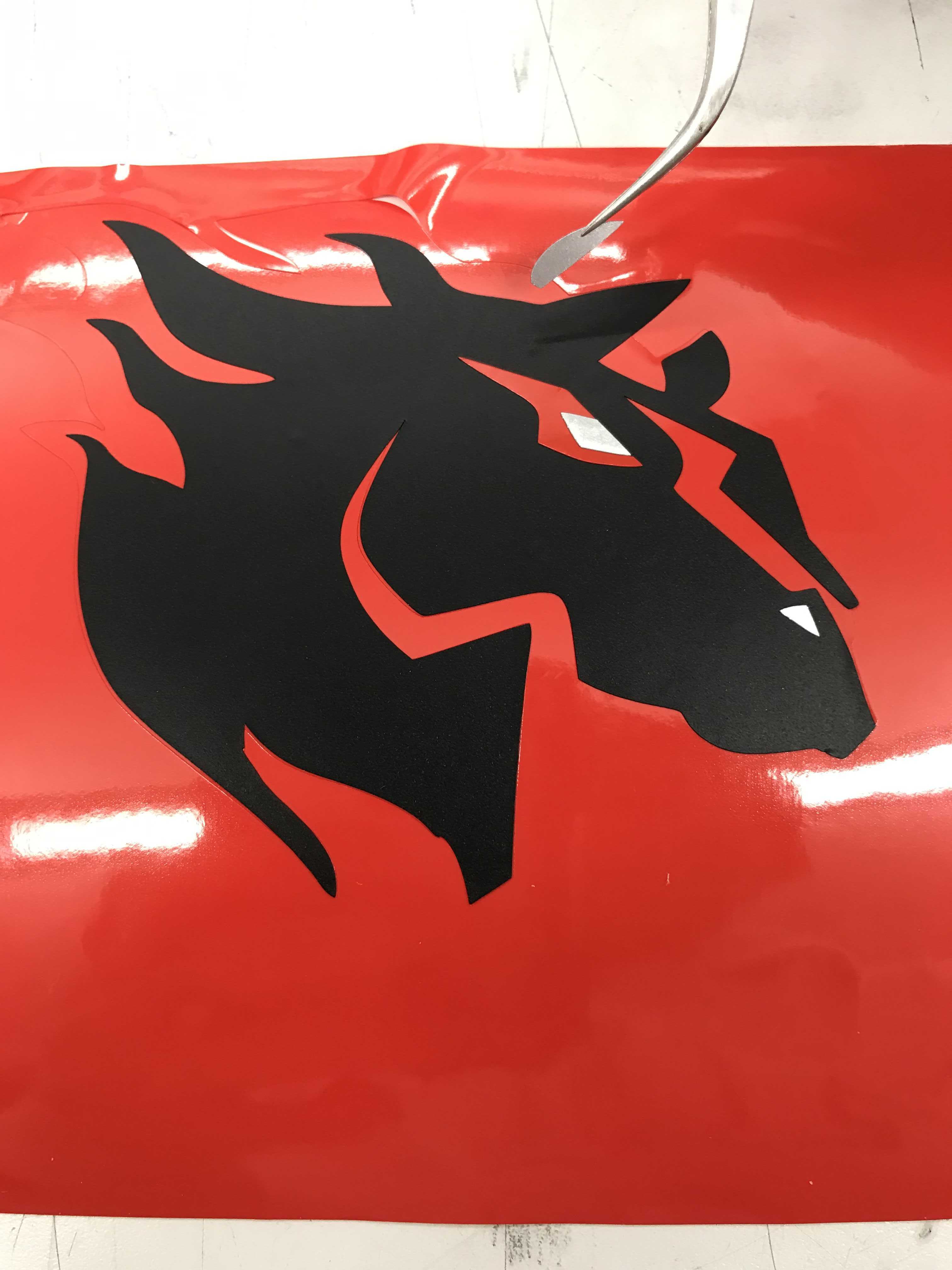
This time, cutting the sticker out was much easier compared to the pyramid as it wasn’t as small and there weren’t as many layers as before. I separated all the different cuts I had to do based on color.
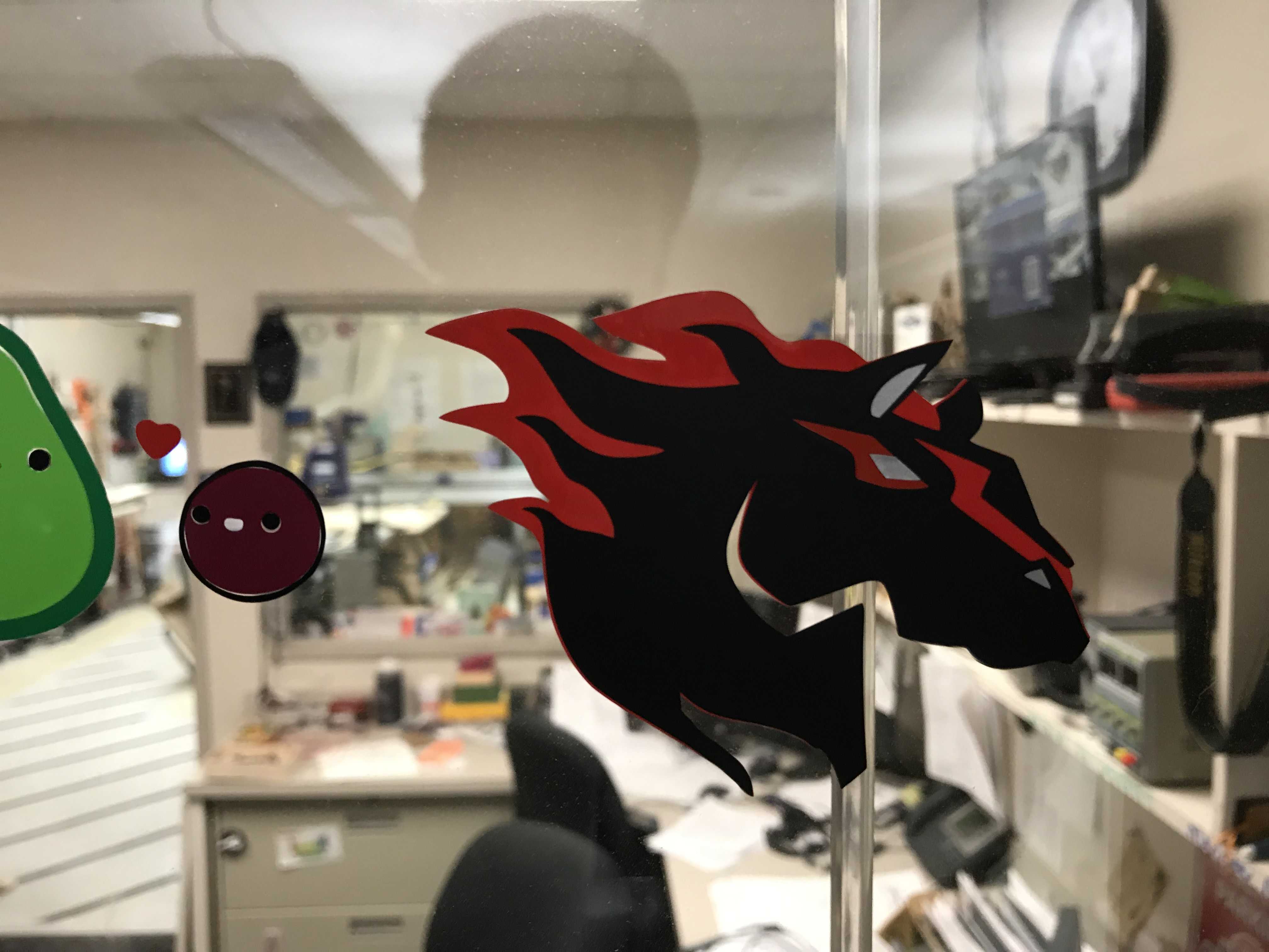
After cutting all the separate layers, I pieced them together and put the final product on the window.
Here are my files to download: Pyramid Sticker Maverick Sticker
Group Project
For the group project, I created and tested the file for measuring what speed, power, and frequency did to lasercuts. Color Mapping and Setting all the color values took a while but eventually I got them done. I helped Vincent write the website in HTML in addition to sourcing, renaming, and compressing all the images we needed to complete the documentation.
Here is the link for the full group project documentation.
Parametric Design
For my parametric design, I decided to create a four element project wtih a base triangle, two different connectors, and a pin. The connectors would be interchangeable and could be set to different angles with a simple change of a parameter in fusion. While these triangles could make a number of 3D shapes, I chose to create a pyramid as it was the most structurally intact.
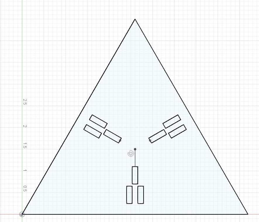
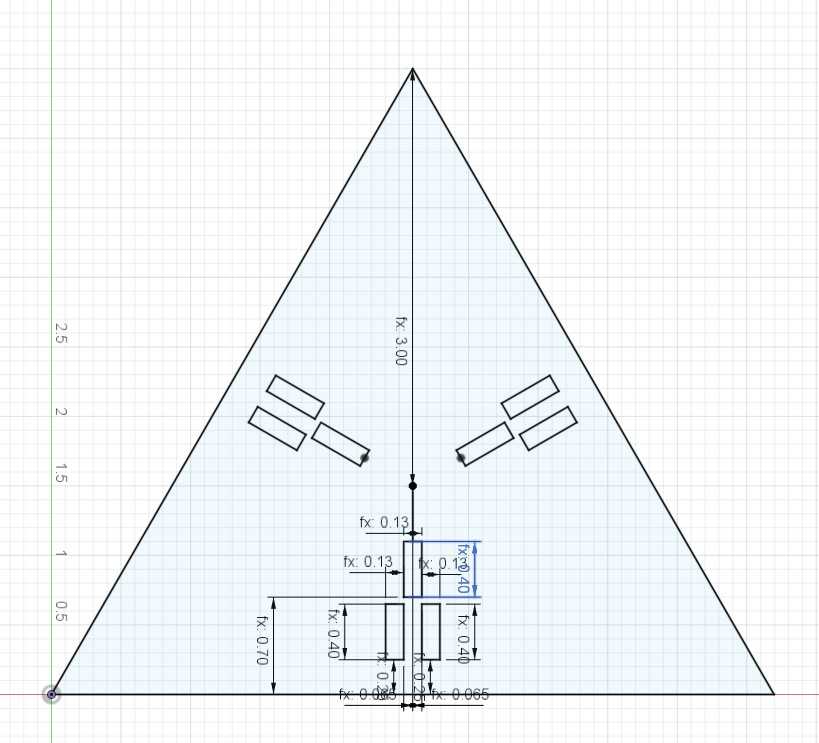
I started with a triangle and created three rectangles where my connectors would sit in each triangle.
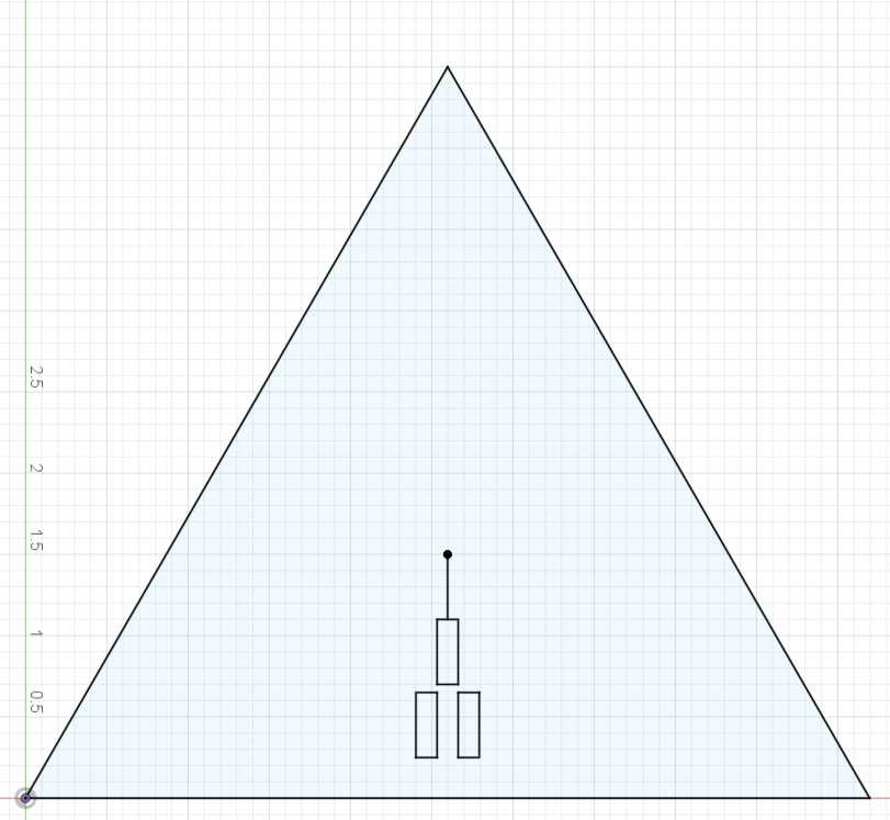
Then, I used a circular pattern to mirror my rectangles on all sides of the triangle.
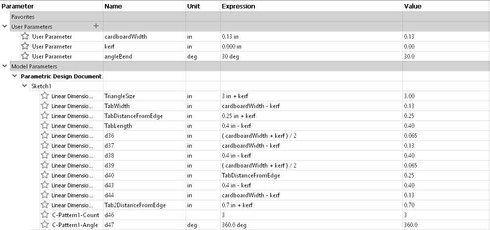
I created three user parameters that would be changed the most: material width, kerf, and the angle of the connectors. I originally set kerf to zero so that I could create my measurements without having to worry about it yet.
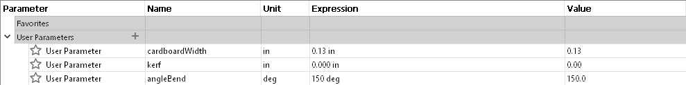
Every smart dimension in my project included either a +kerf or a -kerf at the end of every function as I had to account for it on every cut. On every outside cut, I had to add the kerf to the dimension as without it, my shape would become too small. On every inside cut, I had to subtract the kerf to the dimension as the opposite would happen where the shape would be too big.
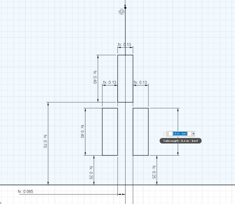
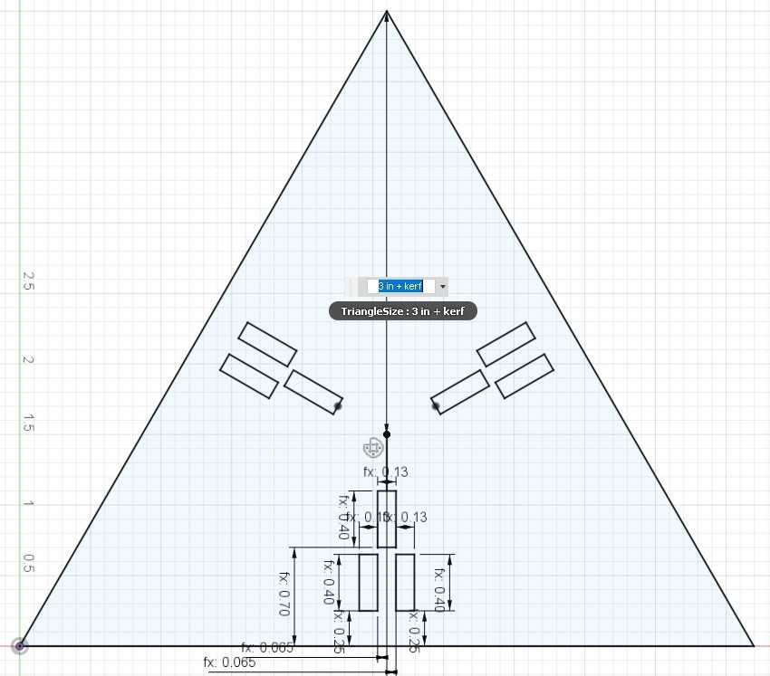
Every dimension within my project was constructed likewise and I named various important parameters for easier access on later sketches.
Now that my base was finished, I moved on to the connectors between each triangle.
The holes on each triangle side will not always be used by a connector but will allow for each triangle to do different things based on the connectors it has. The two holes closest to the outside will hold a short connector while the holes closest to the inside of the triangle will hold a long connector that is harbored in between the two short connectors.
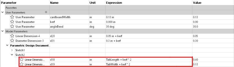
I started on the the bottom of the connector that would be inserted into the base triangle’s holes. The dimensions were created by using the parameters previously named for the base triangle. However, in the base triangle, the holes had the kerf subtracted to it but now we want the kerf added to it as this is now an outside cut. Thus, we need to add 2 times the kerf to make it the right dimension when using the laser cutter.
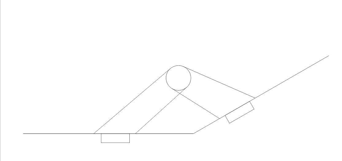
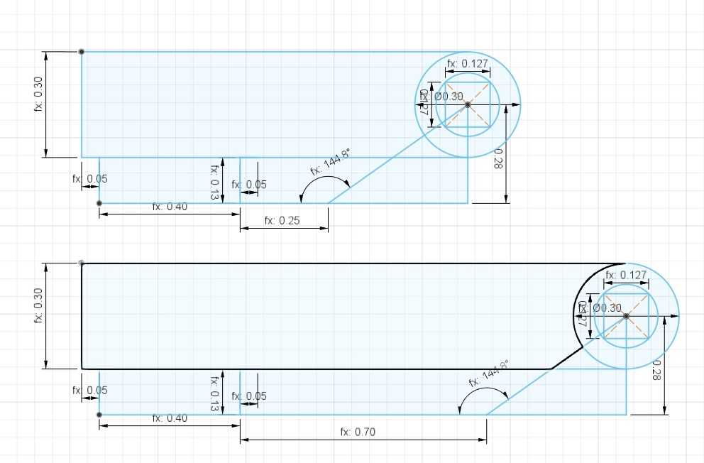
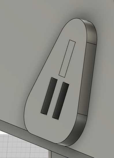
Now, we need to figure out where the opening for the joint will be for the connector. I made a little diagram to figure out what dimensions were crucial to creating my connectors.
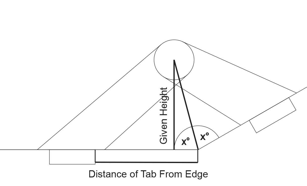
All I needed was the distance from the base holes to the edge, a randomly picked height for the joint, and the predefined angle for our triangles.
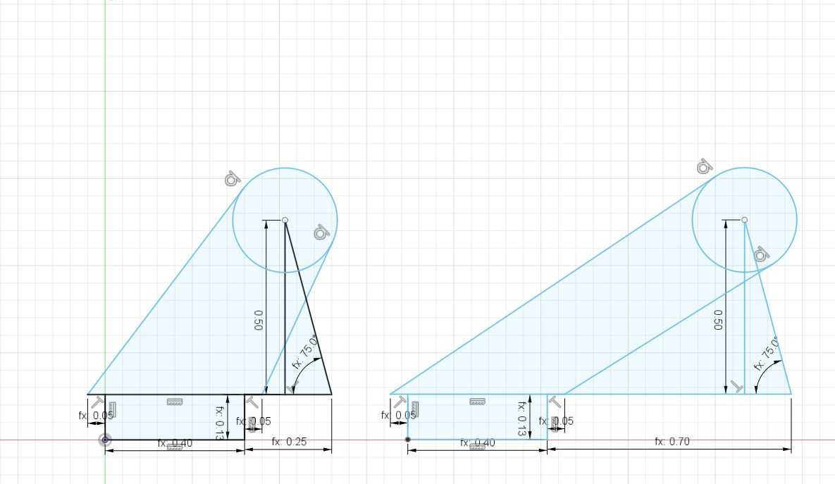
Once this was implemented, all I needed now was how large the joint circle would be. Since the pin that would join the connectors would need to be a rectangular prism due to how the laser cutter works, I needed to define the joint circle based on the my rectangular pin. Half of the diagonal of the pin would become the radius of my join circle.
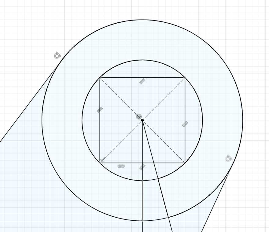
The final piece was the pin and this was simply a square base with the width and length as the thickness of the material with the height spanning three thicknesses of the material as there are three joints to pass through.
Here is what it would look like in 3D:
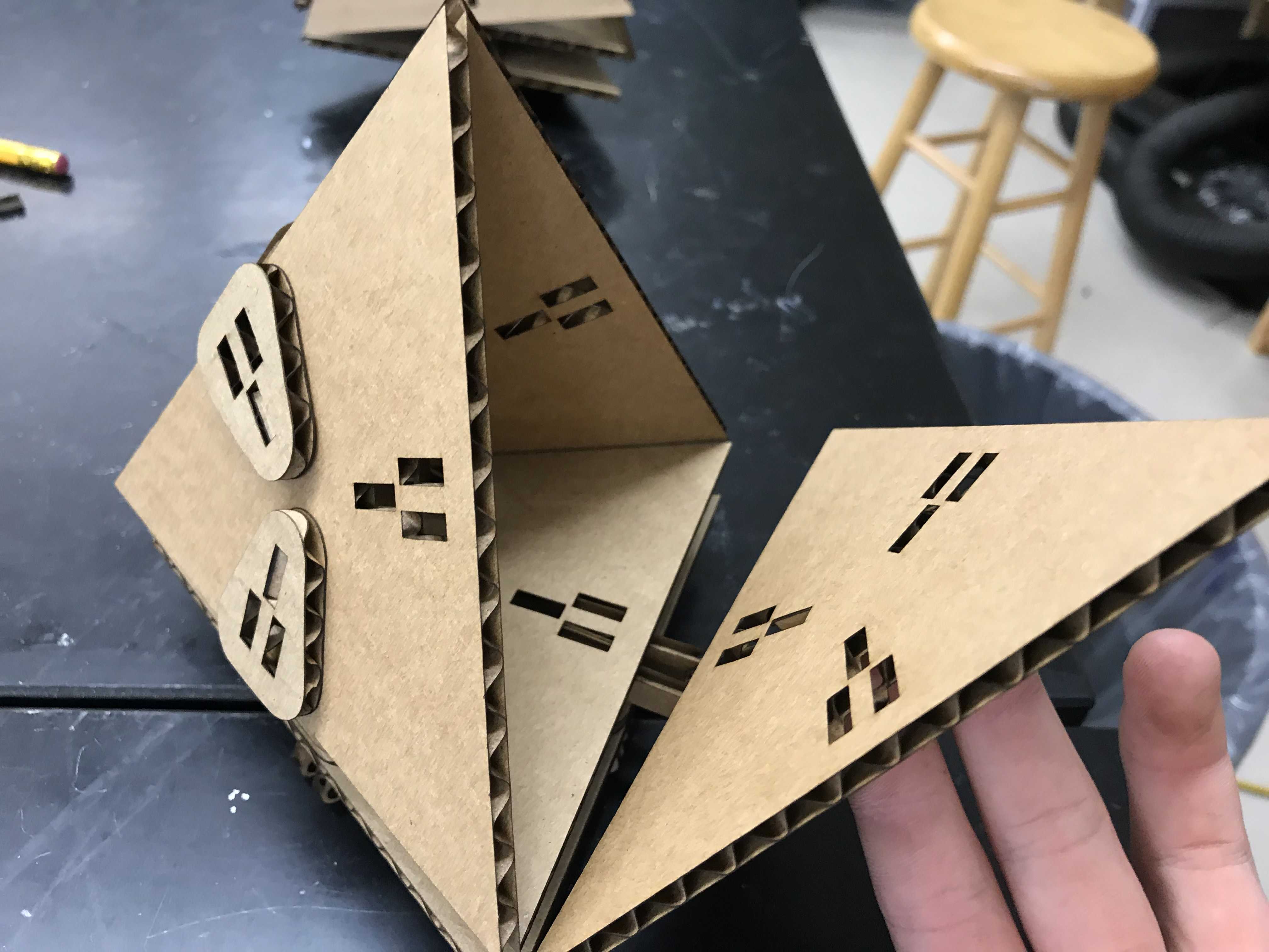
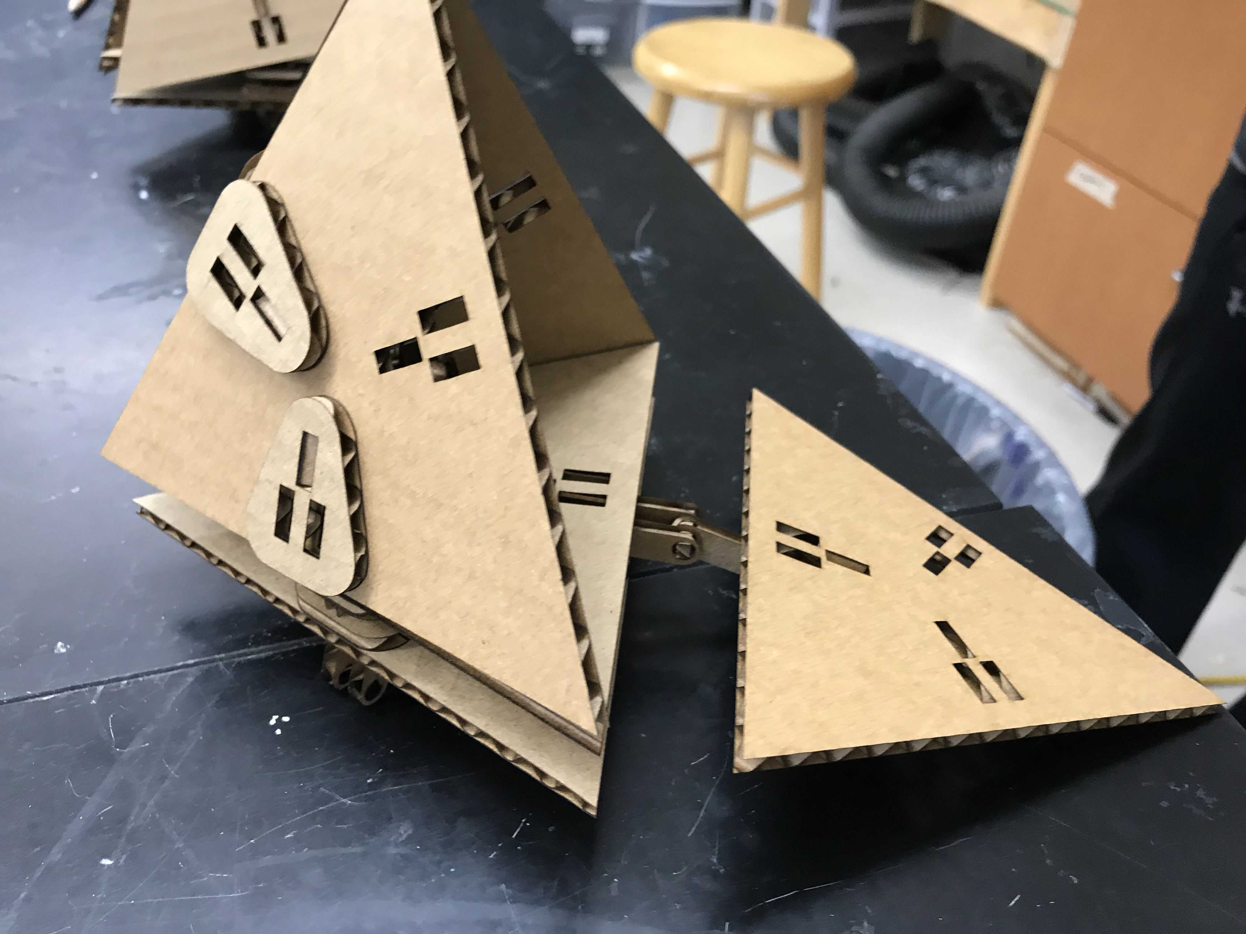
For fun, I made one more connector that would allow me to open up base triangles like doors. This was created using connectors where the joint circle was not elevated off the connector. For example:
Here is a design I made with all the components I have created:
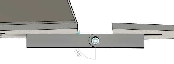
At first, I set the pieces to a set carboard thickness of 0.153 inches and a kerf of 0.05 inches. The angle of my joints was set to roughly 70.5 degrees as this was the rough angle needed to create a pyramid. This was then exported from fusion into CorelDraw as a DXF file and some positioning lines were erased. The Epilog Helix was set to a speed of 15, a power of 50, and a frequency of 500.
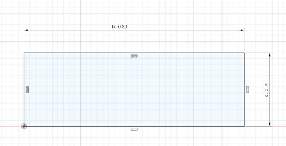
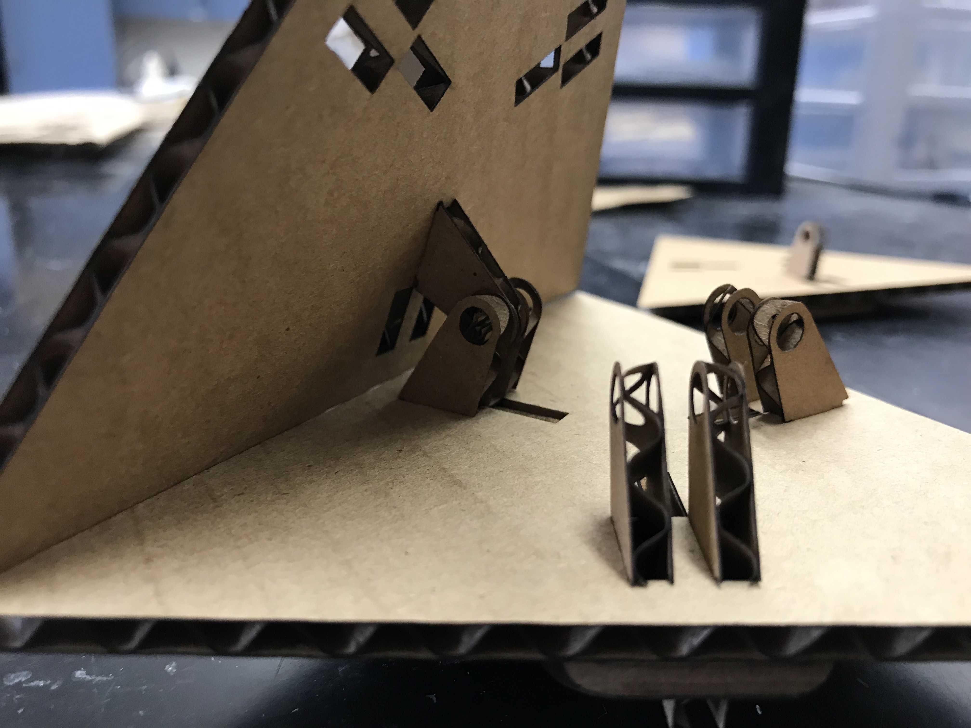
Originally, it seemed like my pieces fit together decently, there was too much give on the entire structure in the end. Pieces did not stay where they were supposed to be and fell out of the structure. Thus, I extended the length of the tab
and created a piece to fit on the protruding part of the tab.
This made it so that the connector would have to loosen itself from two layers instead of one. The structural integrity of my design was strengthened tremendously as a result.
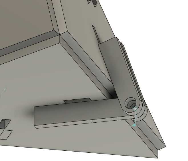
I put it together bottom up starting with a stand for the actual design. This was done in order that the structure be level. The feet were just connectors that were repurposed and they were connected to a base triangle along with my new piece.
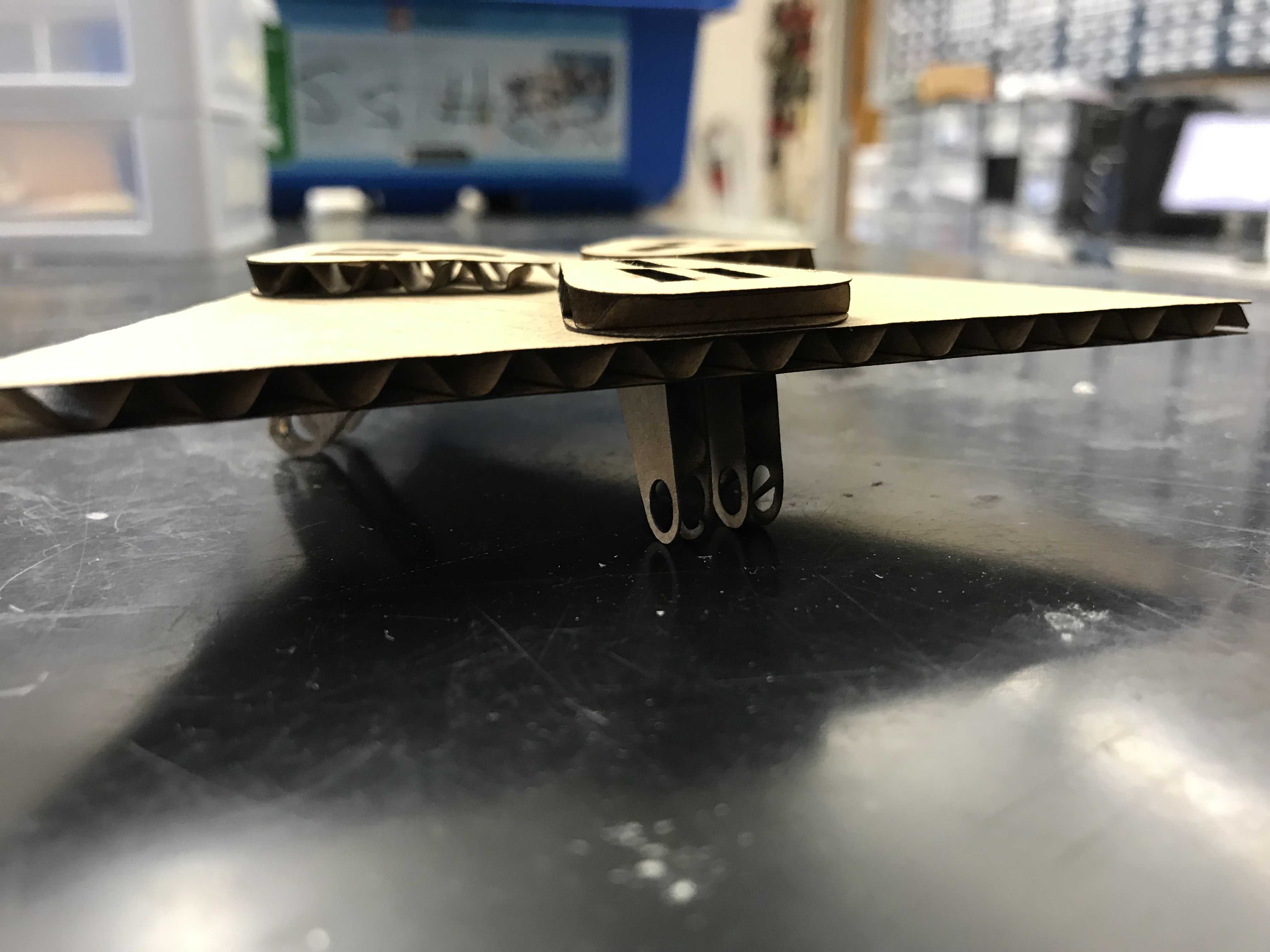
I then added another layer of the new piece along with a little spacer as I needed a bit of room for my joint.
![]()
![]()
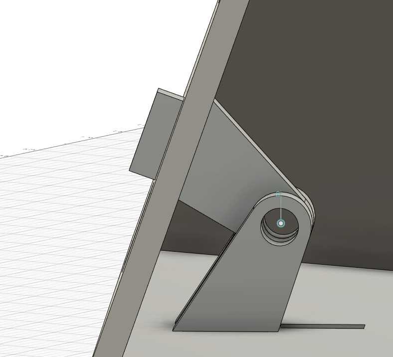
Another base triangle was sandwiched on top of that and the outer two connectors were applied to the base triangles.
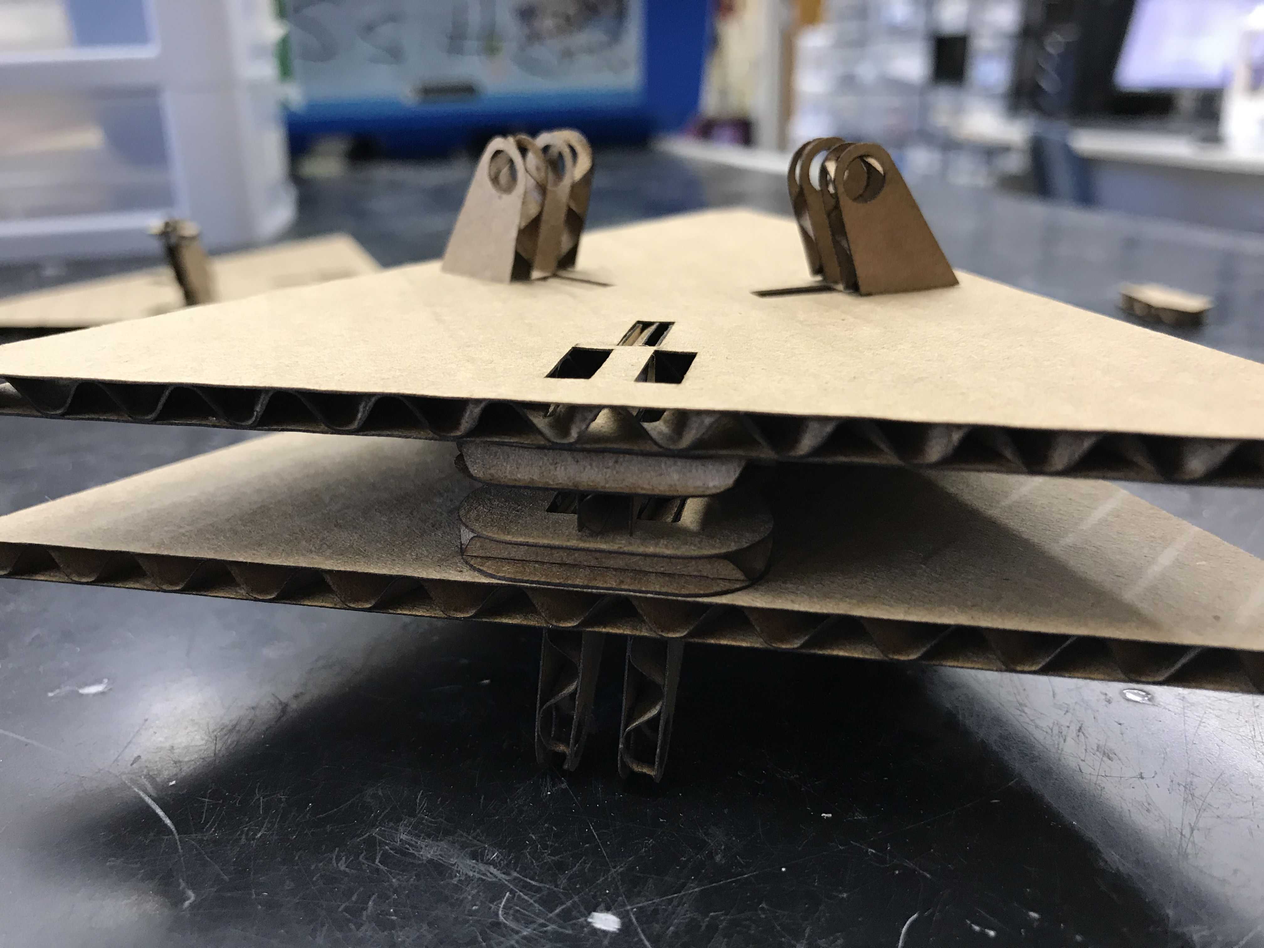
One more base triangle was used along with an inner connector with a pin running through the hole to create one side of the pyramid. The pin was simply a small rectangular prism of cardboard.
This was repeated on the other side to create two sides of the pyramid along with a few connectors in between to hold it together.
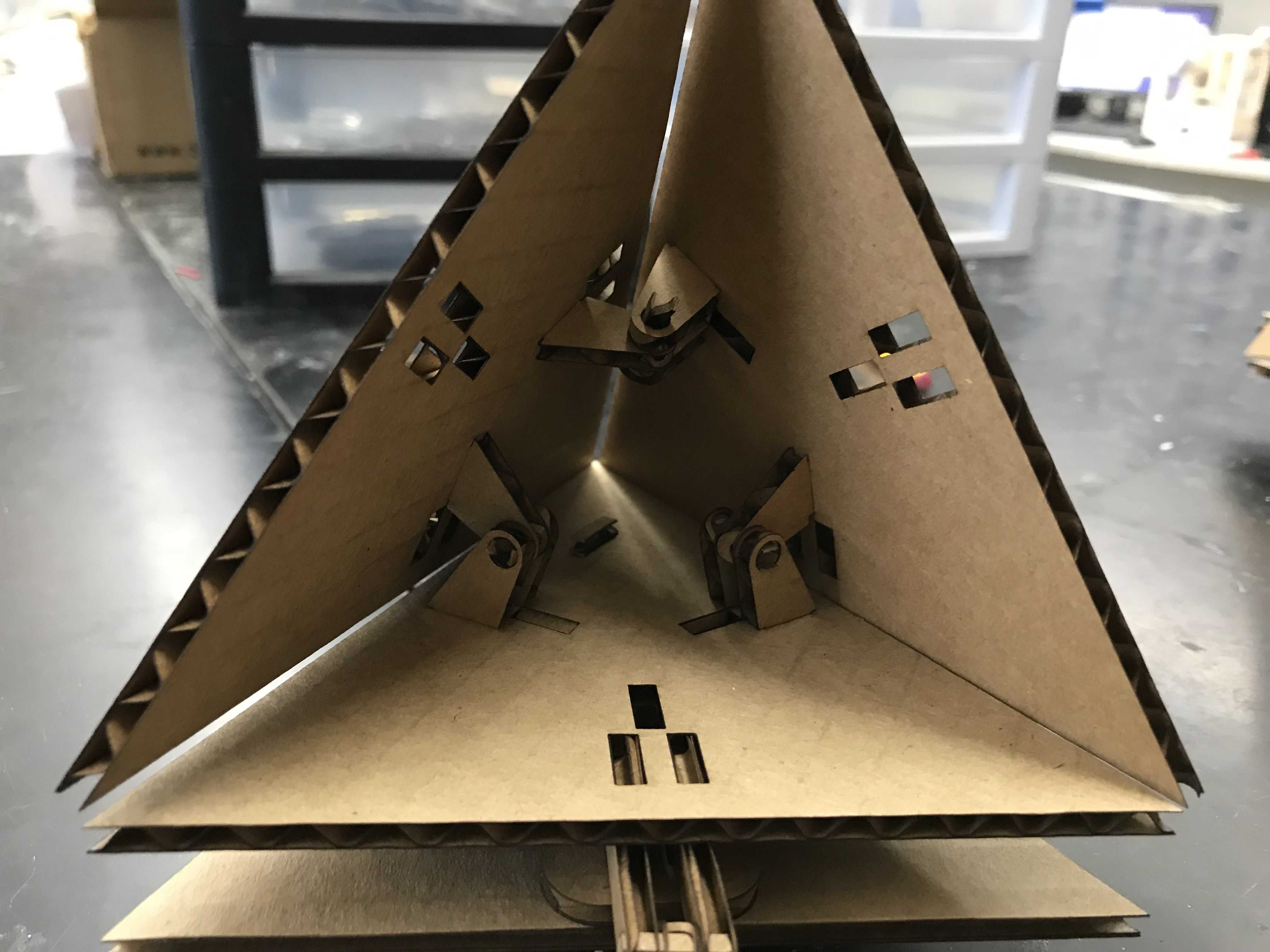
At this stage, I could have either made an enclosed pyramid but I chose to create a door on the last side.
Here is what I made in the end in 3D:
Here are the files for this week: download