Charlotte Latin 2020 Week 4 Group Assignment
Electronics Production
Characterizing the Milling Machine
For the group project this week, we characterized the design rules for the PCB production process: document feeds, speeds, plunge rate, depth of cut (traces and outline) and tooling. We use the Bantam Tools' Othermill Pro and V2 For the software, we used Bantam Tools' free software
Concept Definition
Concept Definitions:
| Term | Meaning | |
|---|---|---|
| Feed rate | The speed of the tool's movement in the X and Y axes. It is in the units of inches per minute or mm per minute. | Source |
| Spindle Speeds | The distance in FPM (feet per minute) that the circumference of the circle passes over the work. The best speed is dependent upon the type of material, the size and type of cutter used, the width and depth of the cut, the required finish, the type of cutting fluid and method of application, and power and speed available on the machine. The formula to calculate spindle speed in RPM is RPM = CSx4/D where RPM = Spindle speed (revolution per minute), CS = cutting speed of milling cutter (in SFPM), and D = diameter of milling cutter (in inches). | Source |
| Plunge Rate | The speed at which the router bit moves down the Z-axis towards the material at the beginning of a cut. It varies depending on the bit used and the material being processed. | Source |
| Depth of Cut | The amount of material that is removed in the z axis while milling. | |
| Tooling | The planning and arrangement of tools for the milling manufacturing process. | Source |
To begin, we started by downloading the Traces and the Outline. In order to obtain the Gcode files for the toolpaths, we used Fab Modules. Upon opening the program, we selected 'Input format' and clicked on 'image (.png)'. This allowed us to select our PNG of the ruler traces. Next, we clicked 'output format' and selected the file type we needed to mill the ruler, 'Othermill (.nc)'. Then we clicked 'process' and were prompted with bit size options, to which we selected the 'PCB traces (1/64)' and when we repeated the process for the outline, we chose the 'PCB outline (1/32)'. To generate the toolpath we clicked 'Calculate', and finally saved the file. We followed these steps for the outline as well, and once the files were created we went to the milling machines to mill the ruler. The following video shows the overall process to creating the G-code.
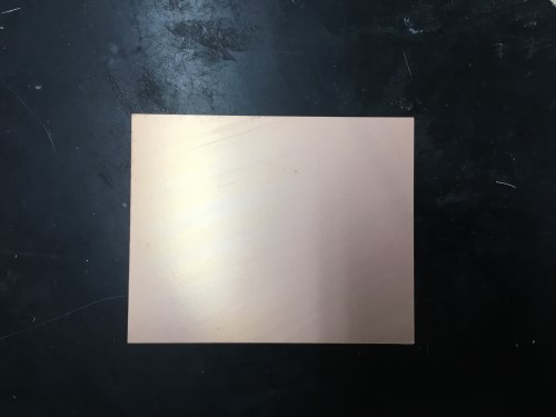
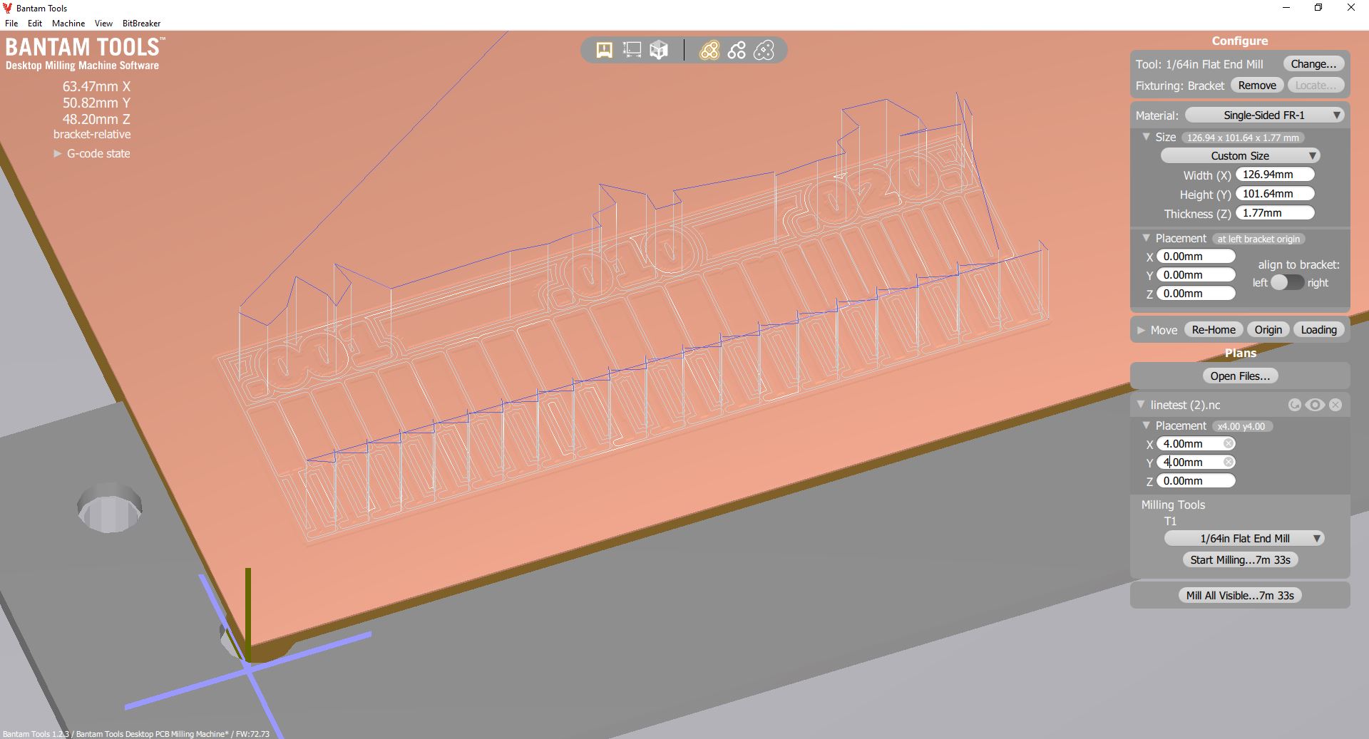
We changed the cut depth to 0.003 mm for the traces file, and 1.77 mm (the thickness of the PCB) for the outline file. Then we saved both .nc files and imported them in Bantam tools. In the Bantam software, we selected our material (Single-sided FR1), measured the length and width of the board with calipers, and entered those values into their respective fields.
.jpg)
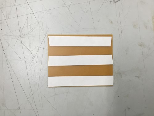
We then applied Nitto tape to the back of the PCB board and applied to the bed of the mill, lining it up to the bottom left corner of the bed.
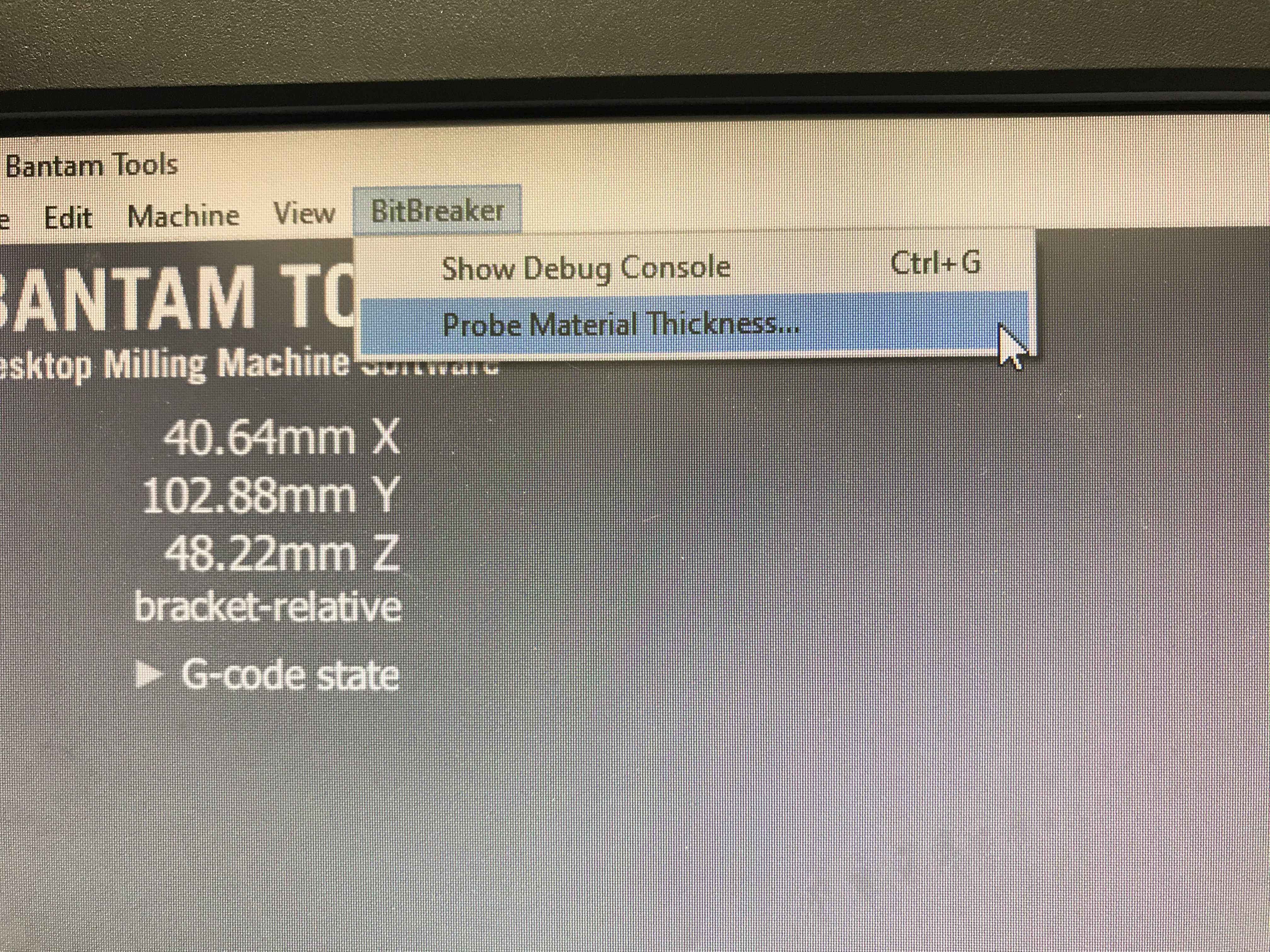
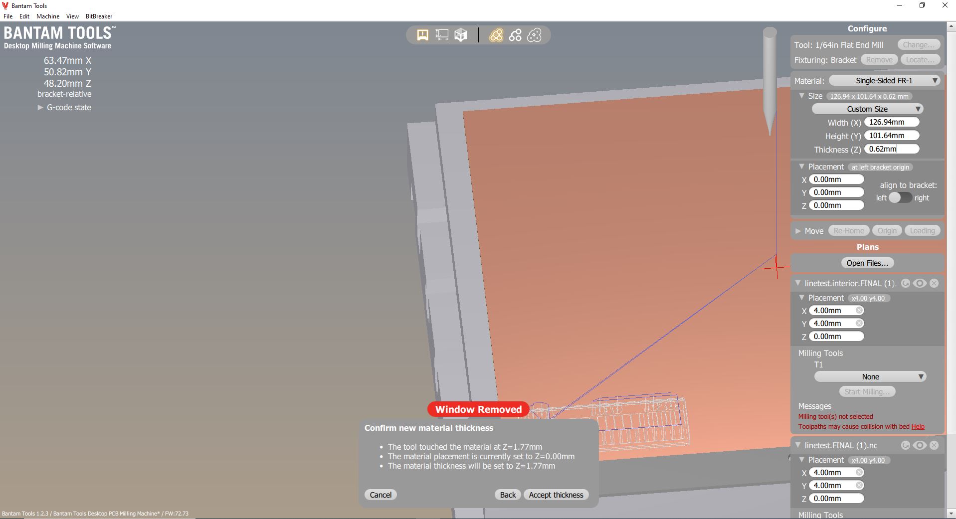
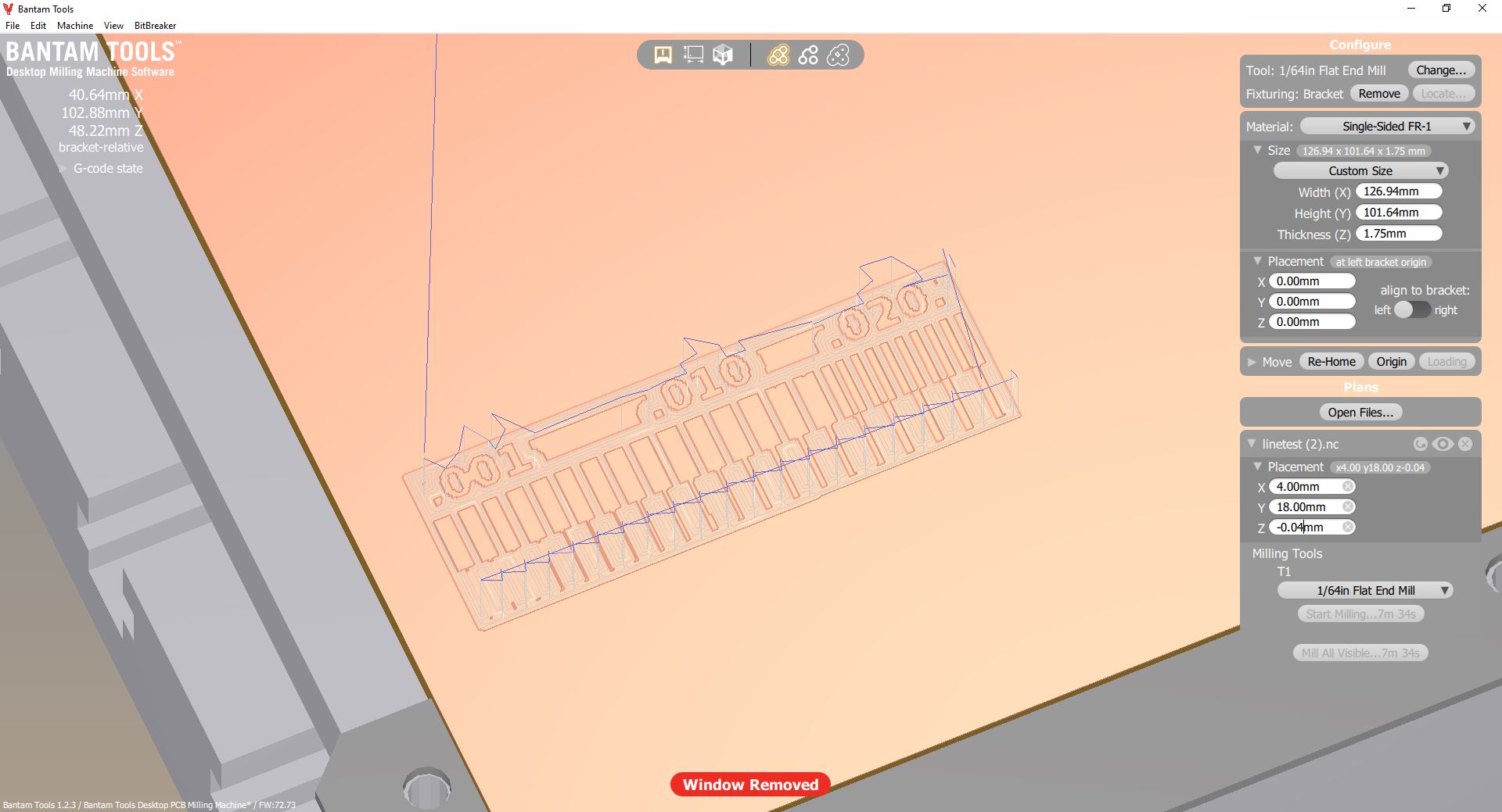
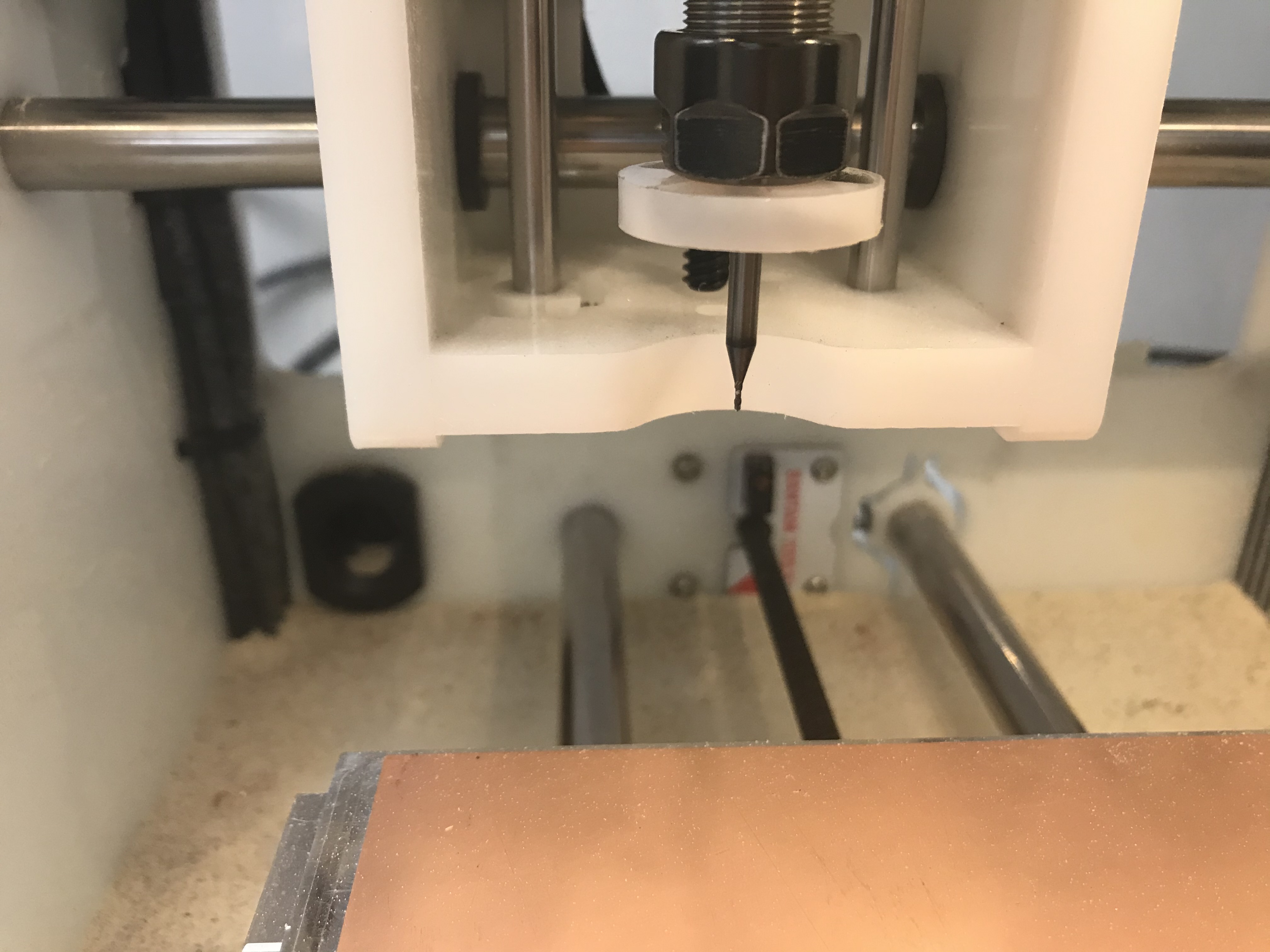
From there, we used BitBreaker -> Probe Material Thickness to measure the thickness of the board. We realized that the cut depth on the G-code was a little small to cut the copper layer, so we changed the z placement of the file to -0.02 mm. We made sure the proper bit was selected, and we clicked "Start Milling" and watched the machine do the rest of the work. However, the traces did not mill evenly, so there was a lot of trial and error when we ran "bit breaker" to figure out the z height. Eventually we were able to fix this issue by simply changing the position by -0.06 mm, but it took a few minutes.
Then we switched bits to the 1/32" bit and imported the outline file. We repeated the process of measuring the PCB FR-1 board and placing Nitto tape on and sticking it onto the bed. We measured the thickness of the board using BitBreaker "Probe Material Thickness", and we clicked "Start Milling" and let the machine finish the process.
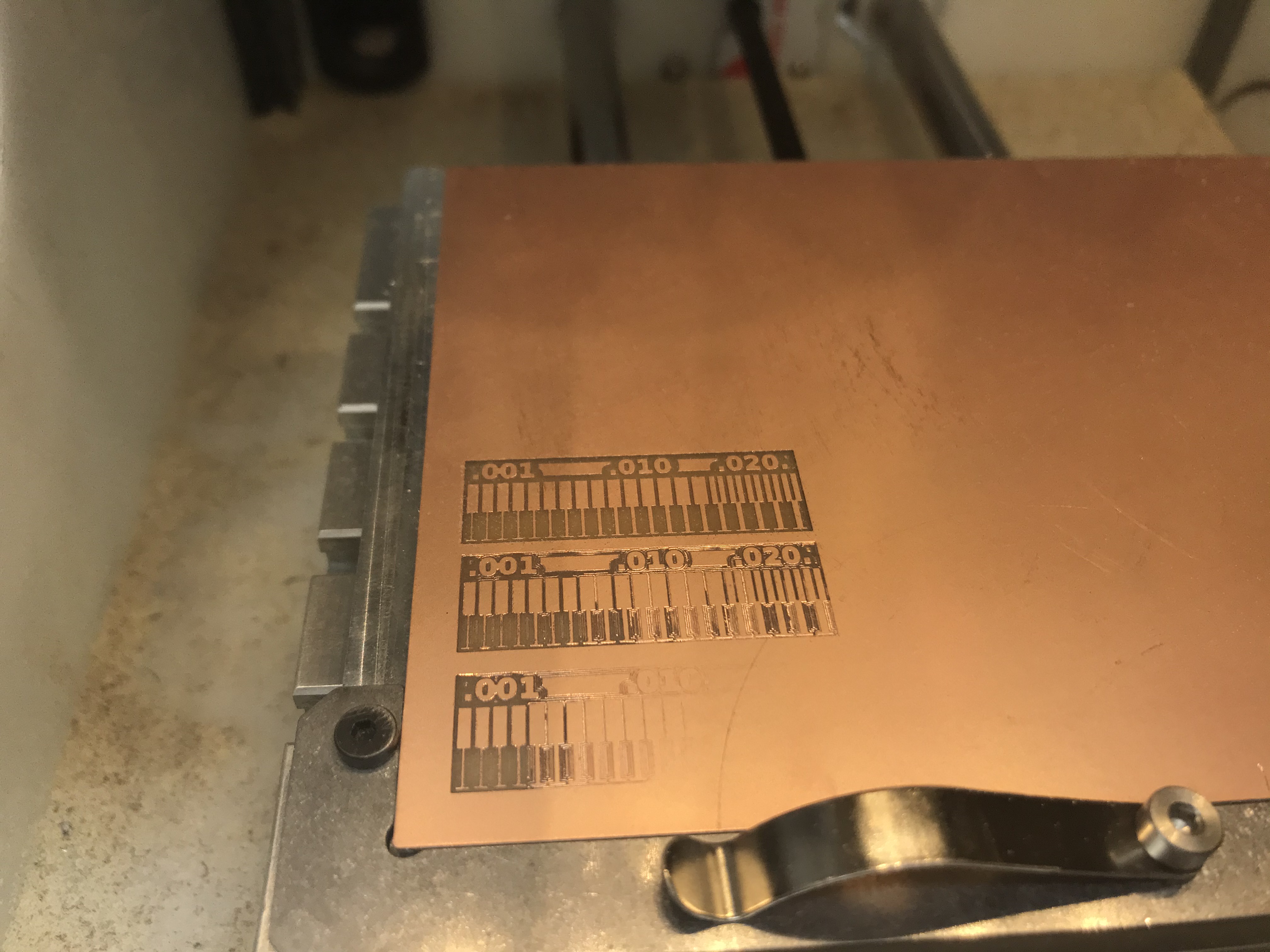
This is what the final ruler looked like.
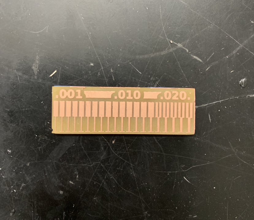
The Bantam Tools website also outlines the surface mount package capabilities for the Othermill Pro on Bantam Tools Surface Mount Package Capabilities. The characteristics of the mill we used were provided by the default settings by Fab Modules. Bantam Tools provides a chart for the Desktop PCB Milling Machine with the speeds and feeds of different materials that you can view here on the second page for the FR-1 material. Ultimately, we found that the thinnest trace we could mill was the smallest trace on the 0.001", and the thinnest clearance width was 0.016".