Charlotte Latin 2020 Week 6 Group Assignment
Electronic Design
Using Test Equipment
For the group project this week, we used the test equipment in our lab to observe the operation of a microcontroller circuit board. The oscilloscope we used for this group assignment is Siglent's SDS1202X-E. Provided with the machine was a very useful manual that everyone should read before operating the oscilloscope.

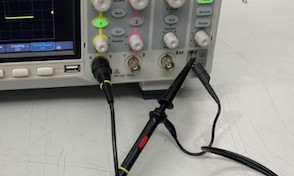
Once the machine is turned on, you can calibrate the machine automatically by first pressing the "Default" button to restore all the settings to its default configuration. Then, plug in a probe into a channel BNC connector on the front panel of the oscilloscope and attach the alligator clips to the Ground Terminal. Finally, click the "Auto Setup" button in the top right corner. In addition, make sure the switch on the probe is also set to 10X.

We decided to measure the operation of the onboard LED on an Arduino running a simple Blink code. The setting of one of the board's pins to HIGH was accompanied with the onboard LED being set to HIGH. We probed the pin being set to HIGH but if we really wanted to, we could have probed the onboard LED directly.
We also adjusted knobs in the Vertical and Horizontal direction to transform how the oscilloscope displayed the waveform.