4. Casing
The casing will be the place to hold the electronic. I have several rule that I want to follow to make it :
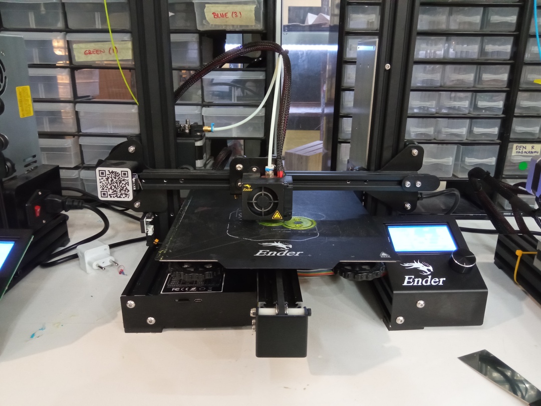
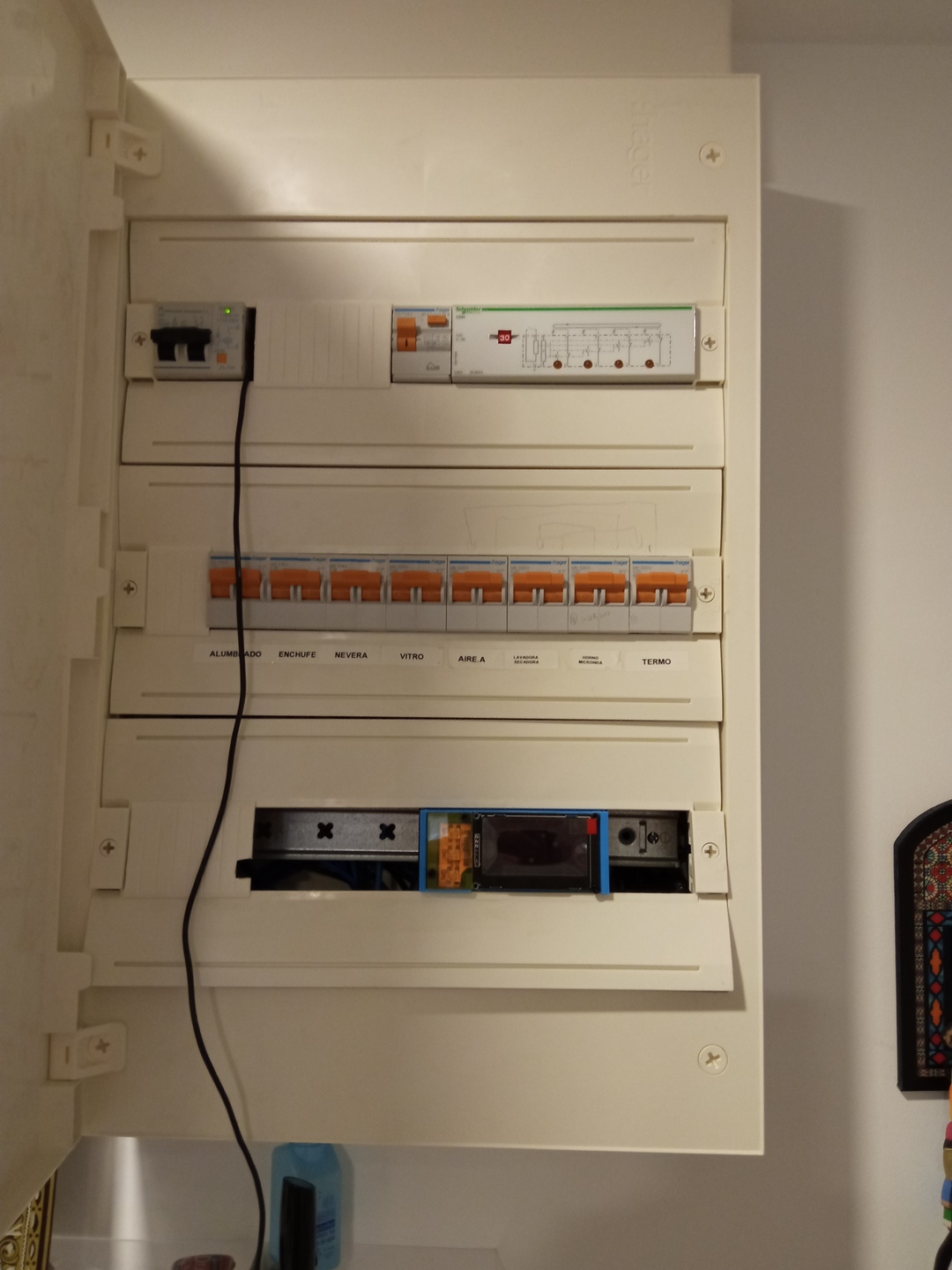
- It must fit in my fuse box
- It must have a minimum amount of screws
- It must accept up to 10 sensors
- Connections should be safe and respect normal fuse design
- I want to be able to flash the MCUs without desmounting it
Base on those rules I started the work on the CAD software.
Warning
I had worked a lot on Rhino because Freecad was not working properly on my computer. But when the final project started my testing license for Rhino stopped and the company who is selling Rhino sharply refused* to extend the testing license for a few weeks. That was as sign more toward open-source software. So I checked the freecad website and saw a new build was available (0.2) and it worked fine on my computer !!!
So FreeCad it will be for the desgin !
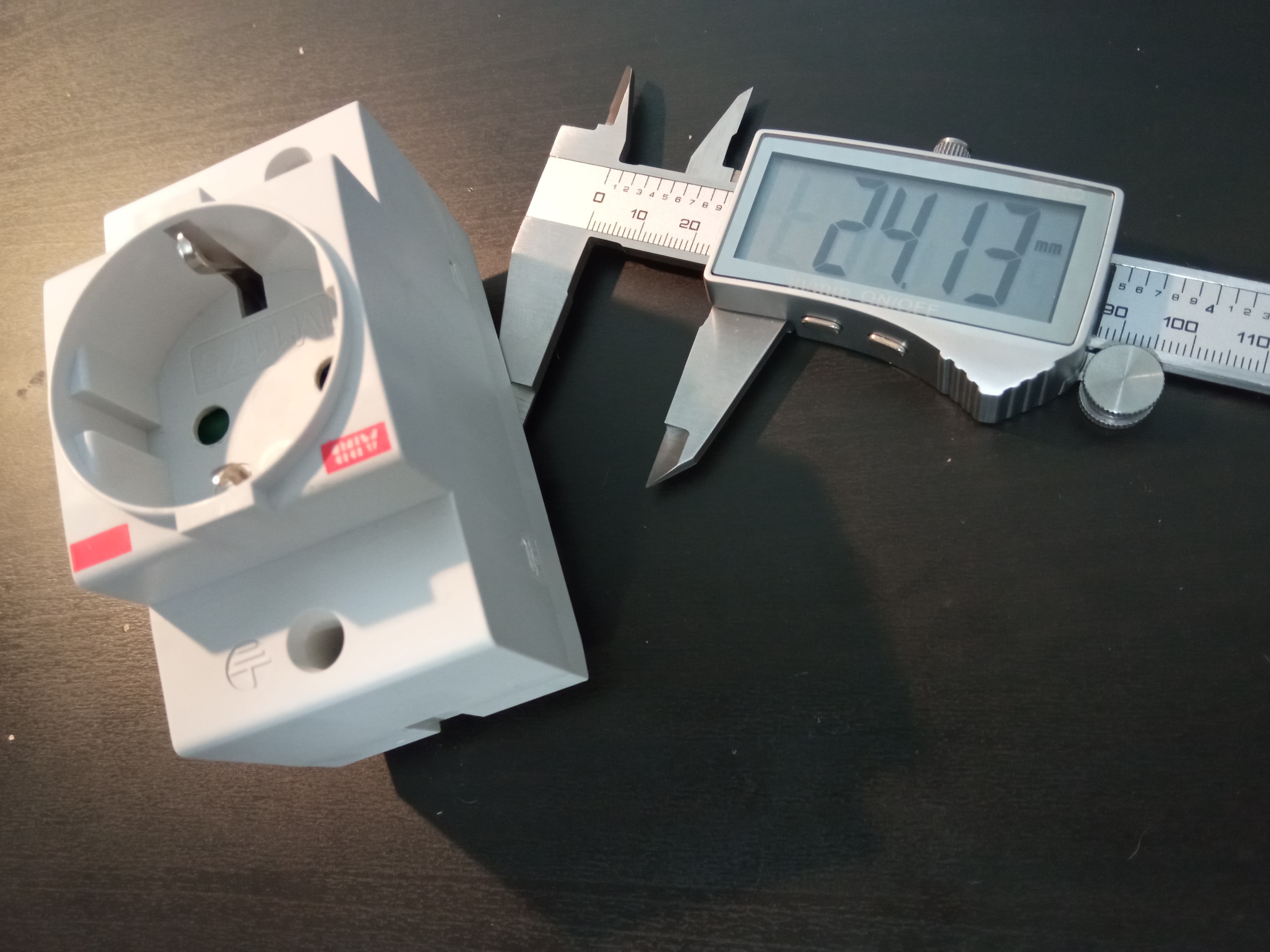
Dimension Sheet
As a start I created a Dimension sheet were I dropped all the main of the model of fuse (a plug that fits in the fuse box by the way) I could get. I also added the dimension of my electronic.
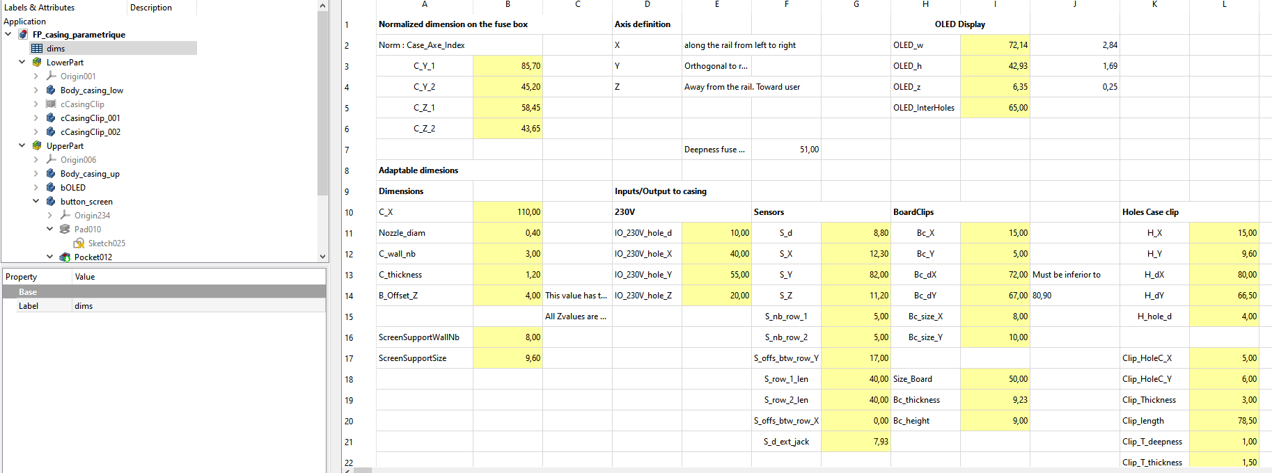
This dimension sheet is used afterward when creating any part. You can refer the dimension to any label created in the dimension sheet. THen if you modify the sheet, the model gets updated. Easy !
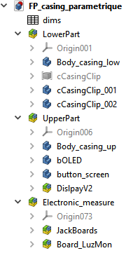
The casing
I split my model in 3 main parts.
- Lower part : The part that is fixed to the rail and receive the main electronic
- The casing itself
- Two clips to fix the casing on the rail
- Upper part : the top part that will receive the screen and buttons
- The top part
- The screen
- The board with buttons
- The metacrylate screen
- Electronic CAD : Imported from Kicad
- The jack board
- The LuzMon board
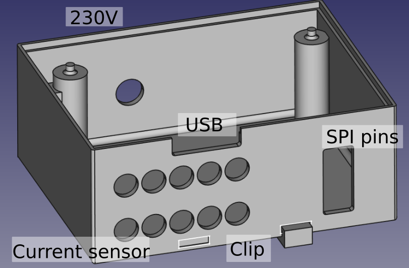
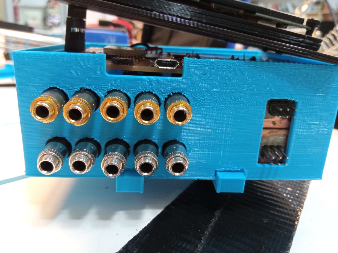
Lower part
For the lower part I prepared the technical holes for my sensors. All of them can be seen on the picture below :
- USB : access to the USB port of the ESP32
- SPI : access to the SPI pins of the ATMegas
- Current : holes to let the jack for current sensor
- Clip : foot print to receive the teeth of the rail clips
- 230V : hole to receive the 230V cable
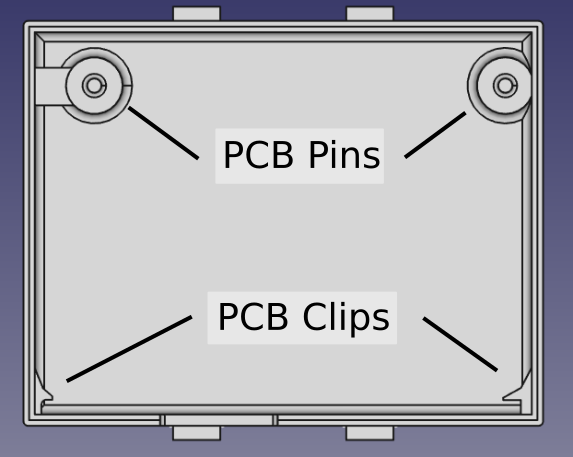
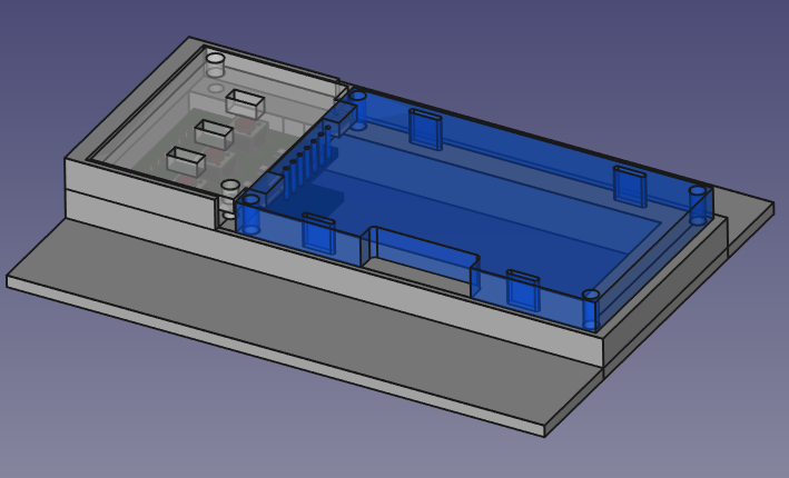
When looking inside this lower part, one can see 2 extra features to hold the PCB’s in place.
- 2 positionning pins for the main board
- 2 clips to let the jackboard enter and then being locked
For those two parts some improvement are mentionned at the end of the page.
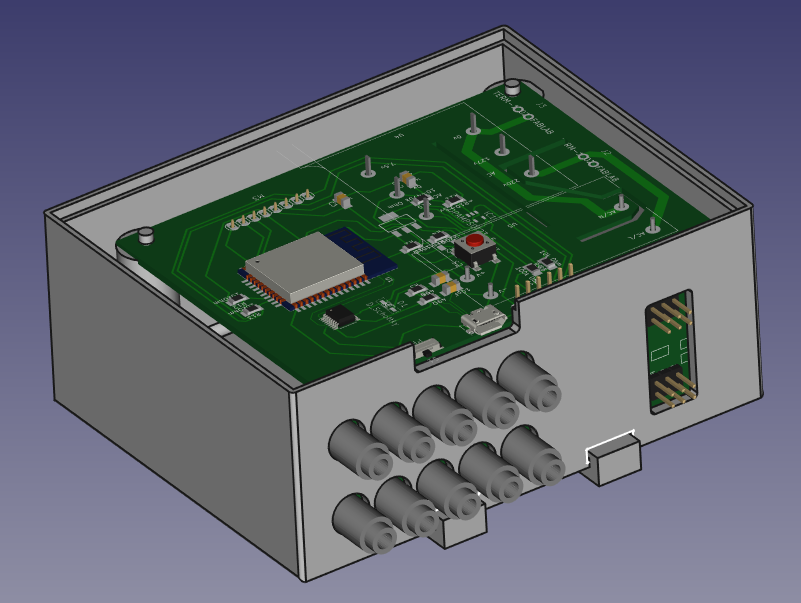
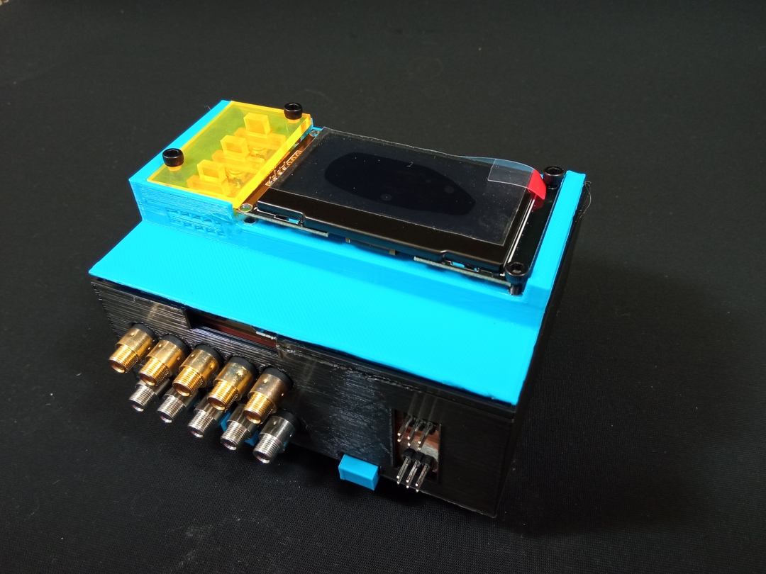
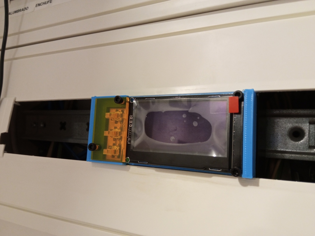
And here is the casing with the electronic nicely fitting inside. The only part I could not make perfect is the height. I was really limited on this part and I have to force a little bit to close the whole thing. I will have to improve this part.
Clips
The clip design comes from Victor Barberan who showed the different models he had used for a robot they have in the Barcelona FabLab.
A good example of how open source design works !
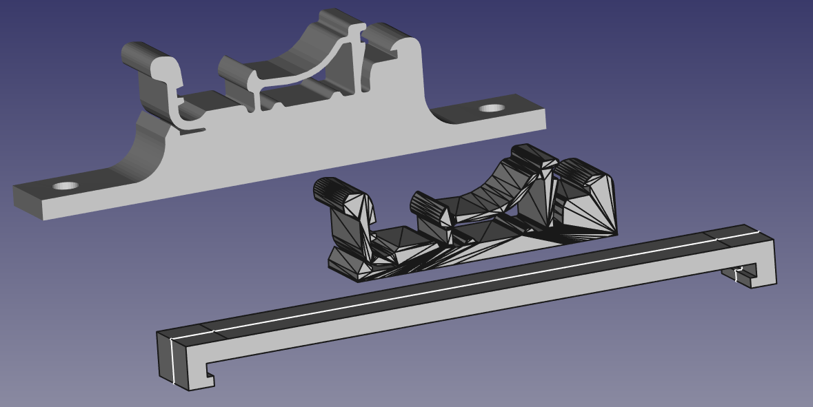
I modified the clip to fit my needs :
- I cut the lower part of the mesh with a nice software called MeshMixer (neither Rhino or Freecad had a nice way to do it).
- I extended it so that it could “grasp” the casing.
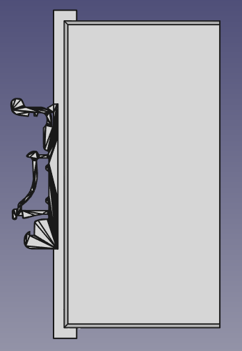
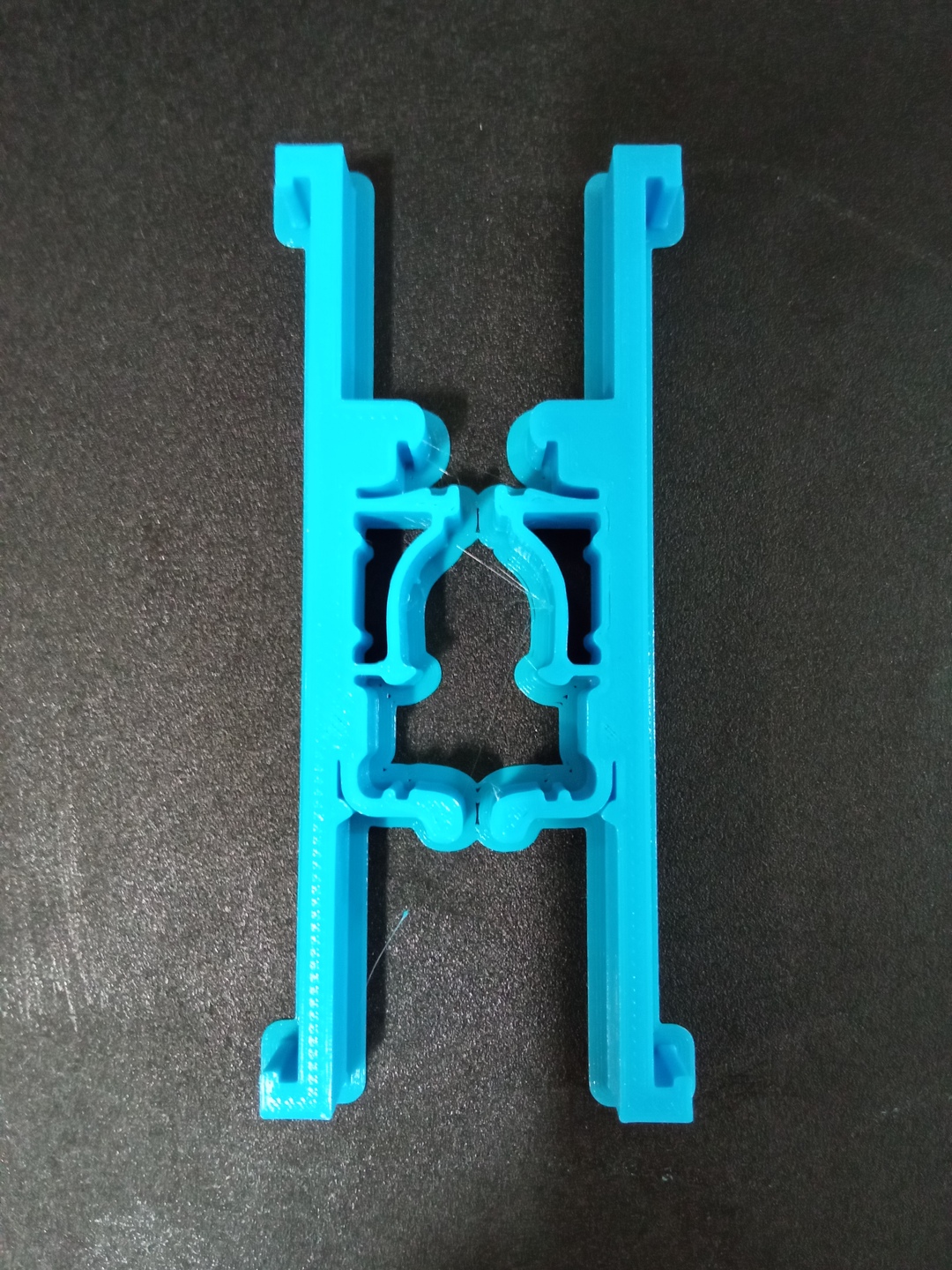
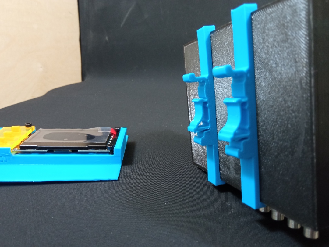
On the picture below we can see the steps of creation on the left and clips finished on the right.
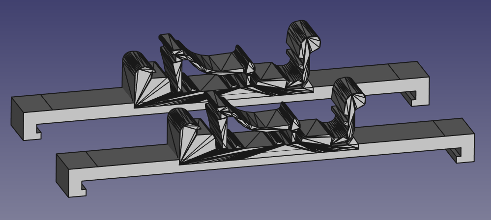
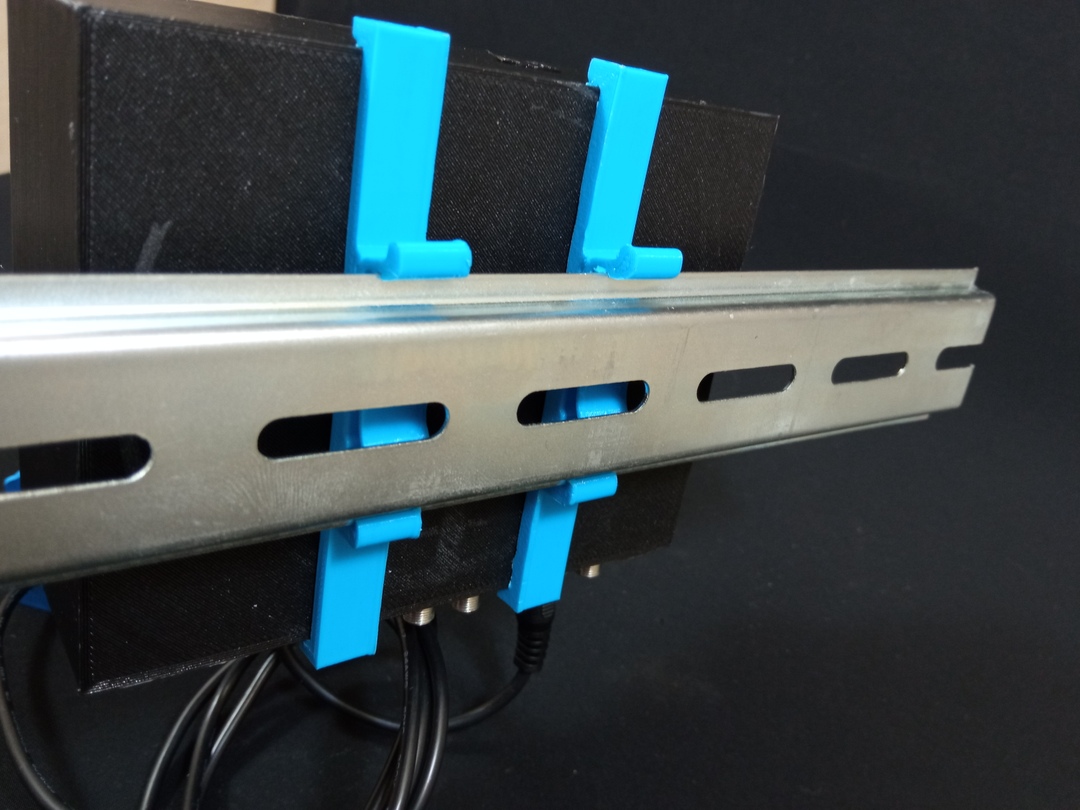
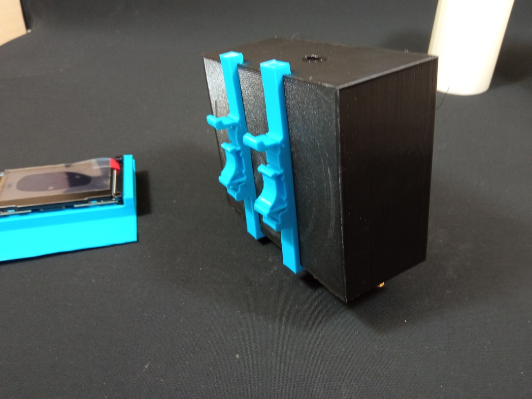
And finally how they fit on the casing.
Enough 3D model, let’s print the clips. It is really nice to design and “instantaneously” have a part that we can touch and test.
Upper Part
Now that the upper part is ready I will desgin the upper part that has the following rules to respect :
- fit in the lower part (obviously
 )
) - fit in the fuse box
- receive a screen
- receive the “Display board” (that wires the screen and the buttons)
- Have a protection for the display board and buttons
Main part
Here is the final design (there were several prototype to reach this one).
In the first model, I had thin walls around the screen that were fragile and useless. So I just removed them. And I also modified the screws position and made space for some components below the screen that I did not have in my 3D model (I desgined it before receiving the screen).
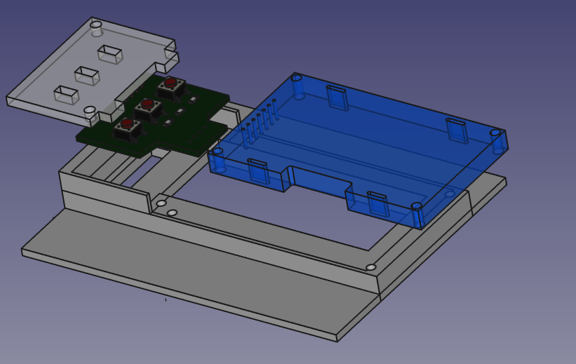
I tested again the Explosion Assembly module of Freecad to make this view to see all the components.
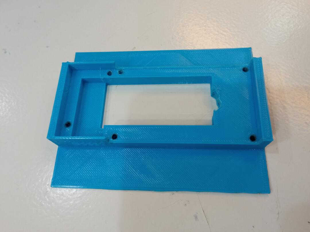
Once confident in the final design I printed it
And here is the result.
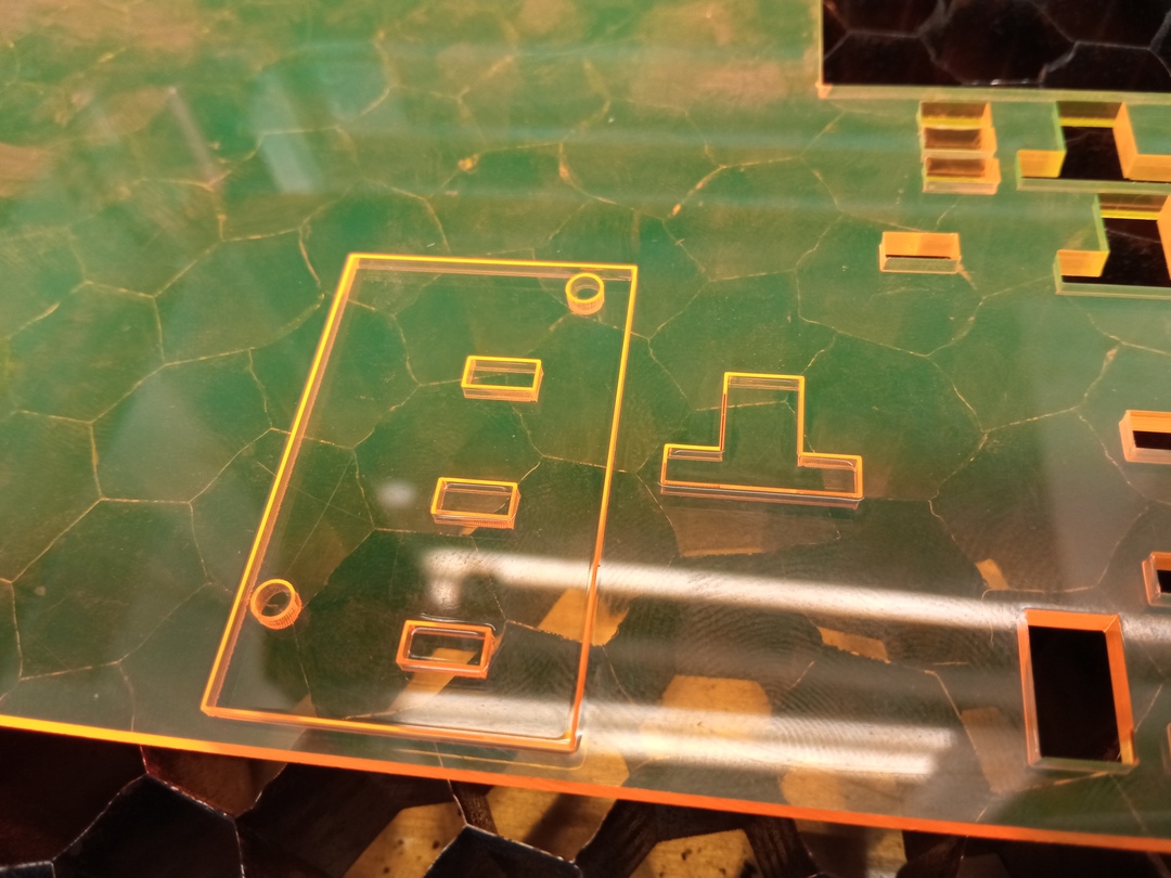
Button Screen
This is the screen meant to protect the display board and the button. I made several cutting test to find the right adjustment.
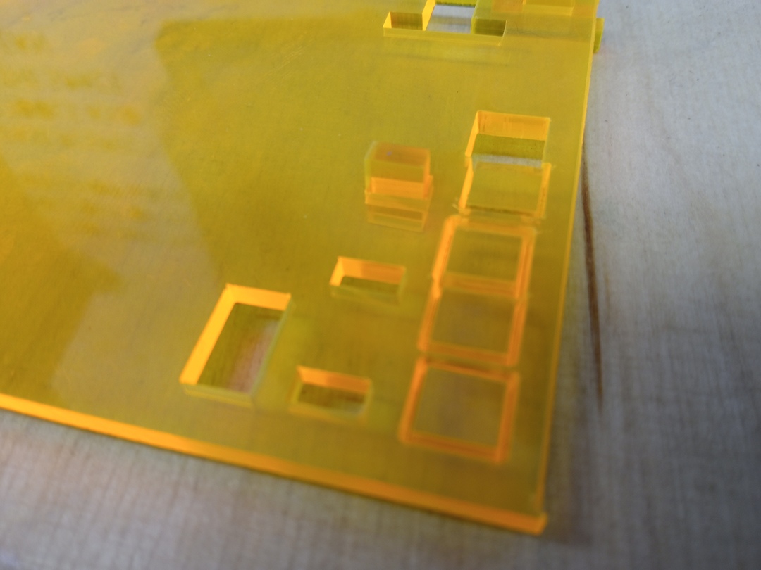
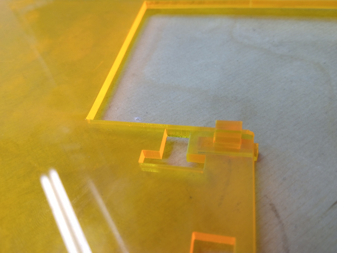
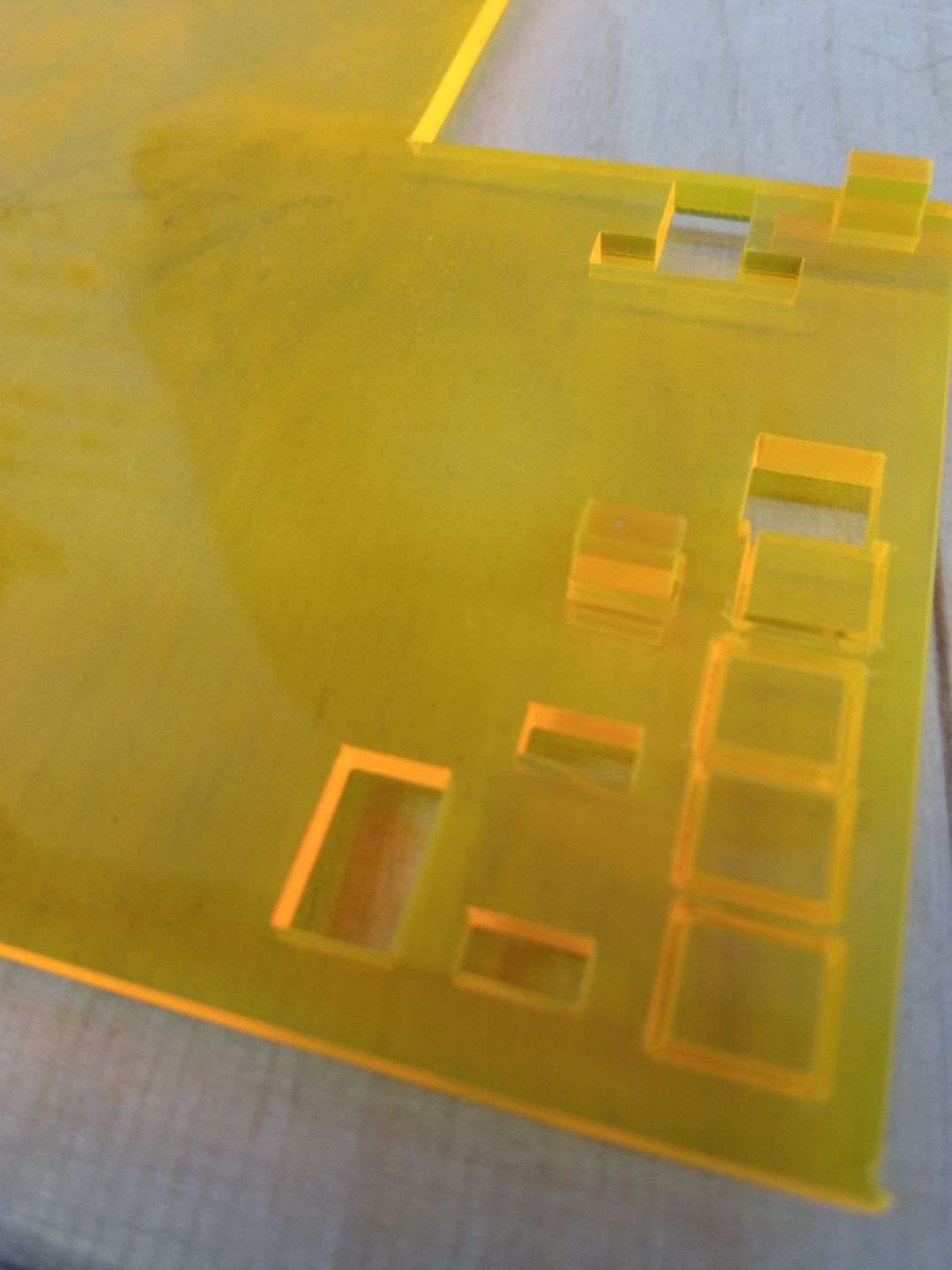
I am really happy with the result. I took the idea from a DIY Oscilloscope I have. The buttons are made of metacrylate and slide without friction in the other part.
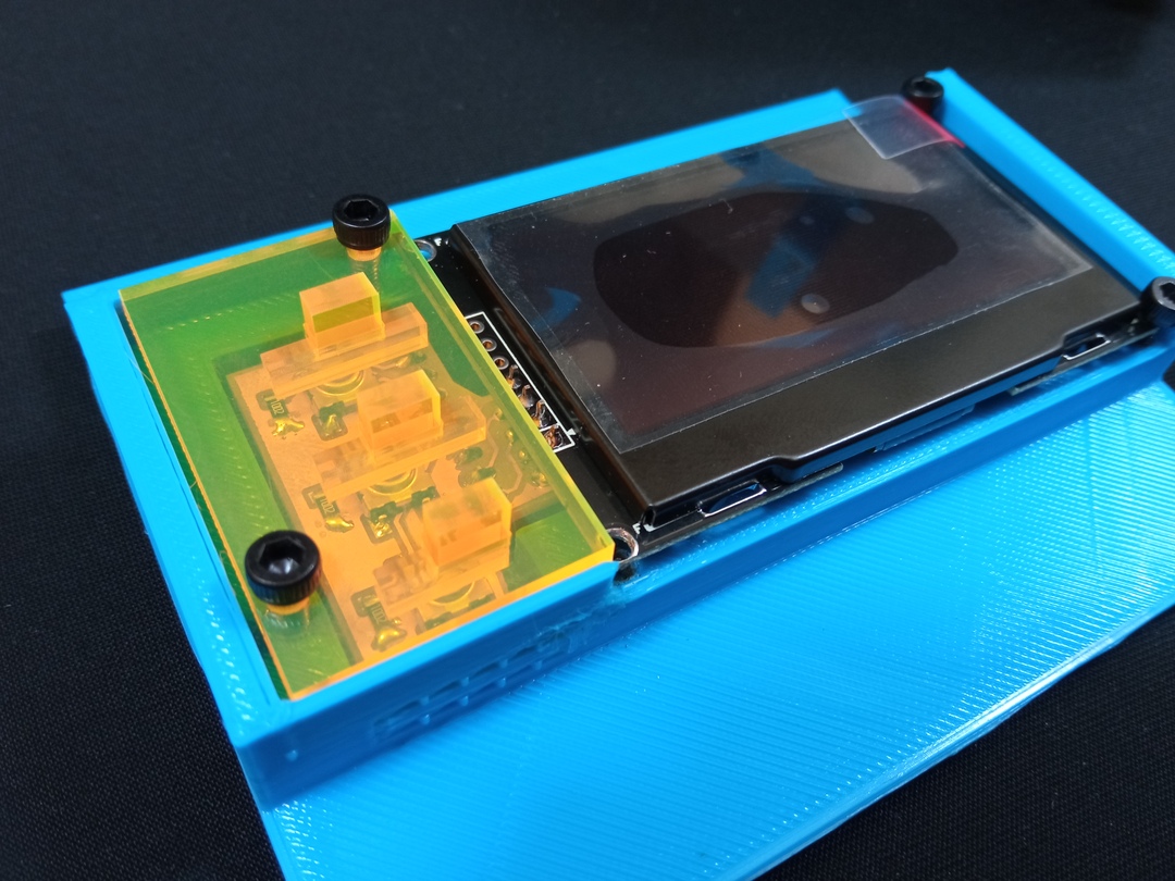
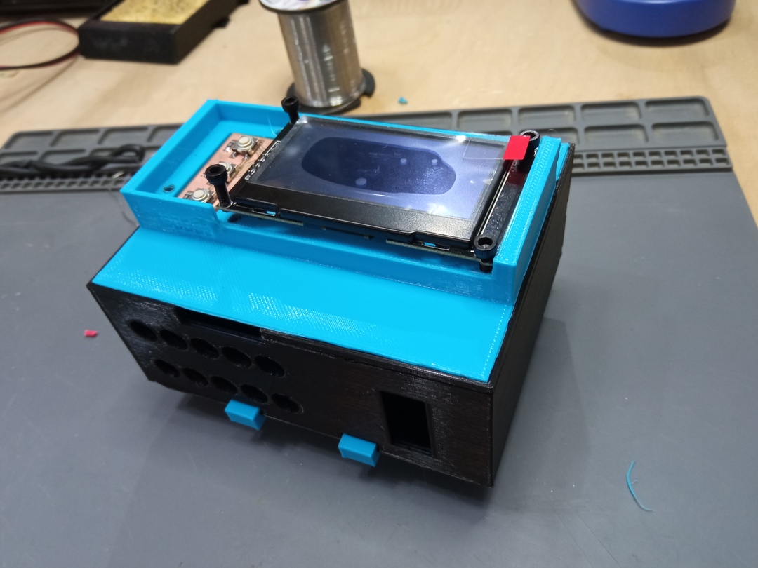
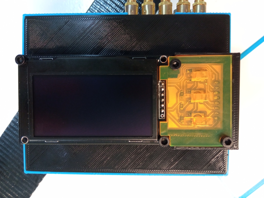
Complete upper part
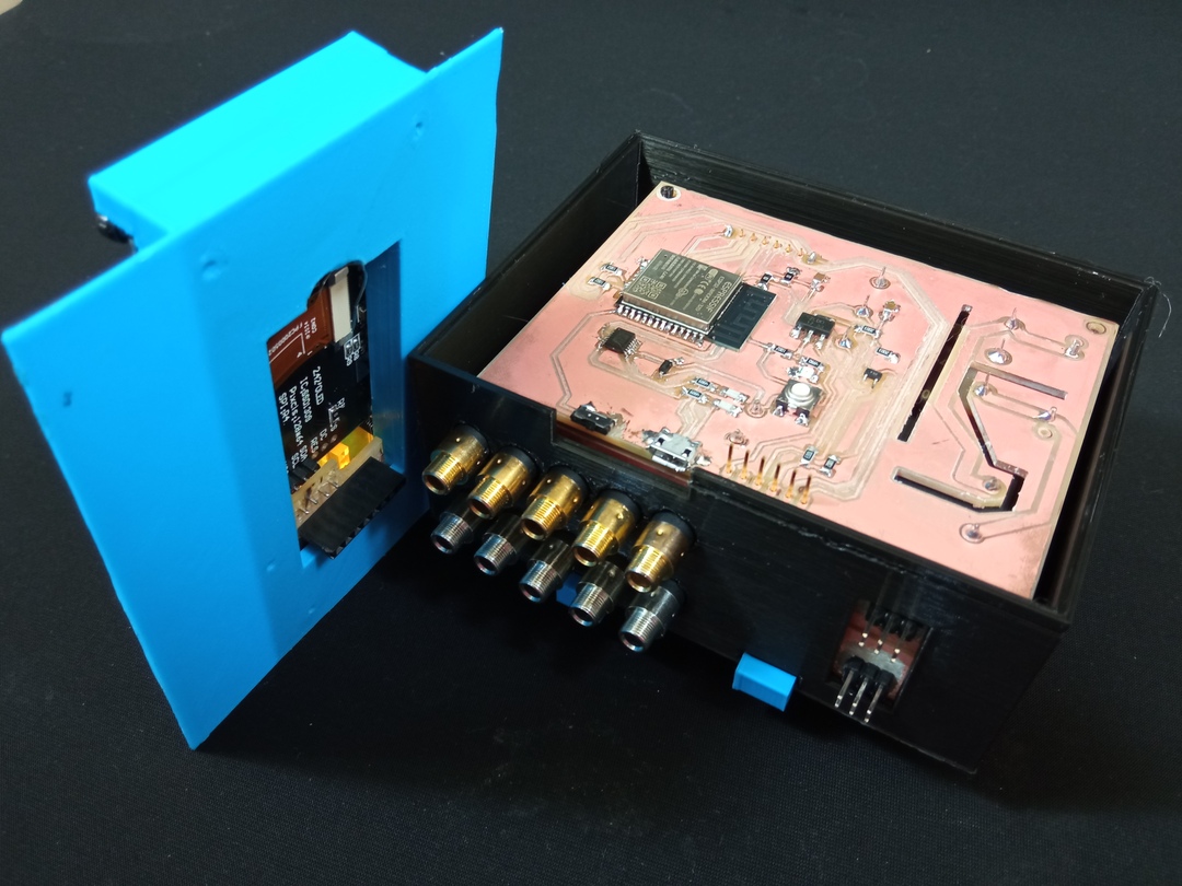
In the picture below I have assembled all the components.
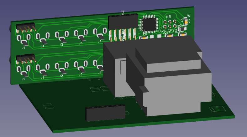
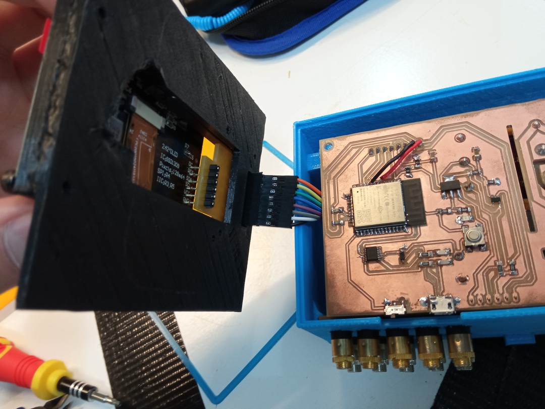
Electronic
Just to show how I work the design, using Kicad function to export 3D model of the electronic
I included it in the 3D model and step by step improved the casing and the electronic
to respect all the rules I fixed for myself. It was an interative painful process .
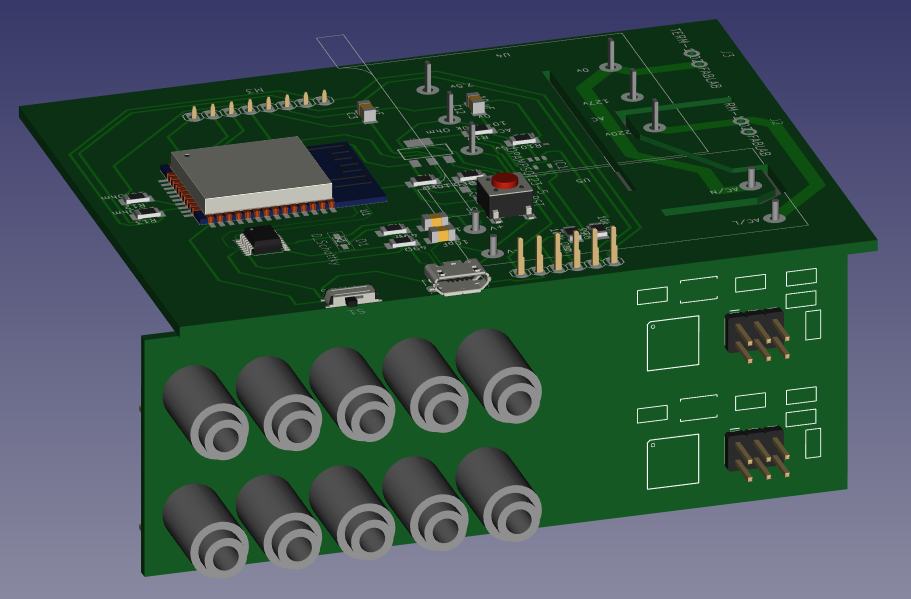
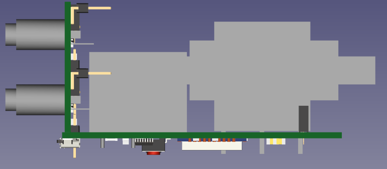
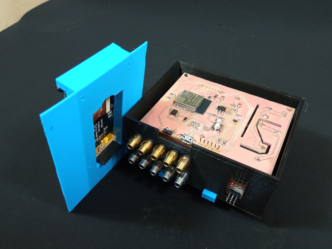
Below one can see how the boards fit together. All the pins were placed thinking about their position in the whole system especially the SPI Pins, they were overlappin with the power source.
Assembly
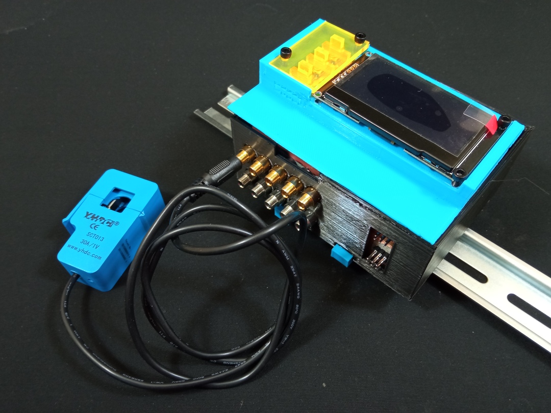
A bit of printing and we are ready to assemble
Final result
Freecad has an extension module that allows the user to create Model Explosion for rendering. Here is a really simple explosion of my 3D model.
Here is the first version I made. Tested the mounting of the whole thing.
The fisrt version lead me to the following updates
- Lower part
- improvement of the PCB pins
- creation of the PCB clips to hold the jackboard
- widening of the 220V hole
- Upper part
- Wider space below the screen for the components
- Update of the display PCB and the hole below because the pins we touching the ESP32
Improvement
- Adding U-cut on the board-clips to put and remove
- Holes for screws instead of pins to maintain PCB (they break to easily)
- Thinner plastic column to support PCB screws (hard to mount)
- Adapt current sensor holes for better mounting
- Add cable inserts to hold 220V cables
- Create a cap for the SPI pins.
- Improve printing settings for a better quality
- Adding sensor number within the design
I might also work on a model that is casted using the possible following plastics :
- https://www.formx.es/products/poliuretano—resinas/task-series/index.php
- https://www.smooth-on.com/tb/files/TASK_4_TB.pdf
- https://www.smooth-on.com/tb/files/TASK_2_3_TB.pdf