13. Networking
Group Assignment
During the class session we worked on several example to interact between boards in different ways.
Wired communication
Serial
The serial communication is being used by the class since day 1 of electronic. I personnaly flash my boards using the RaspberryPi Serial commununication possibilities.
Debugging is also done with function as simple as :
Serial.begin(9600) Serial.print(“Message”)
When flashing this code in a microcontroller a commuPA_AutonomousBoard_Setup.jpgnication bridge is established between the microcontroller and my raspberry to exhange what ever data ( in form of strings) I have pre-established to transfer.
It requires :
- 4 pins (common GND,TX,RX)
- Establish communication rate before hand
To check serial I use different options such as :
- Arduino IDE Serial monitor
- miniterm : ‘python -m serial.tools.miniterm /dev/ttyS0 115200’
- picocom : ‘picocom /dev/ttyS0 -b115200’
I2C
I2C protocol works on the Directory/Managed node relationship (this is the new appelation). I connected several boards together to make them communicate through I2C.
To make I2C work between two ESP8266 I did the following :
- Connecting SDA pins together
- Connection SCL pins together
- Connecting Grounds
- For the Directory node I flashed the following code
    #include <Wire.h>

    void setup() {
        Wire.begin();        // join i2c bus (address optional for master)
        Serial.begin(9600);  // start serial for output
    }

    void loop() {
        Wire.requestFrom(8, 6);    // request 6 bytes from slave device #8

        while (Wire.available()) { // slave may send less than requested
            char c = Wire.read();    // receive a byte as character
            Serial.print(c);         // print the character
        }

        delay(500);
    }
- For the Managed node I flashed this one
    #include <Wire.h>

    void setup() {
        Wire.begin(8);                // join i2c bus with address #8
        Wire.onRequest(requestEvent); // register event
    }

    void loop() {
        delay(100);
    }

    // function that executes whenever data is requested by master
    // this function is registered as an event, see setup()
    void requestEvent() {
        Wire.write("hello "); // respond with message of 6 bytes
        // as expected by master
    }
It was tested on two sets of boards as explained below :
-
ESP32 & ESP32
I had the bad experience that it does not work. Indeed we came to the conlusion during the workshop that the ESP32 cannot work as a managed node. But after further reading during the creation of this documentation I found out that the issue might come from Arduino IDE more than the ESP. Indeed the ESP32 datasheet states that it can work as a managed node in the following chapter 4.1.11 I²C Interface. Now a potential solution is offered by the ESP32_I2C_slave library available on GitHub. I have added it to my “DoOrLearnSomethingonYourFreeTimeList”.

-
ESP32 & ESP8266
This was another failure
 … but a fruitful one
  .
.
I spent quite some time on this setup because it did not work during the workshop so I tried my best to understand why. I used a modified version of the example code due to the research I have been doing. Specially playing on delays, signal casting and Serial.print for debugging.Directory node code
    #define PIN_SCL 22
    #define PIN_SDA 21
    // IO22 = SCL = (Above TX/RX) = Green
    // IO21 = SDA = (Below TX/RX) = Yellow
    String c;
    //Receiver
    #include <Wire.h>

    void setup() {
      Wire.setClock(4000);
      Wire.begin(PIN_SDA, PIN_SCL);       // join i2c bus (address optional for master)
      Serial.begin(9600);  // start serial for output
      Serial.print("ESP32 Start communication") ;
    }

    void loop() {
      Wire.requestFrom(8, 6);    // request 6 bytes from slave device #8
      while (Wire.available()) { // slave may send less than requested
        //Serial.print("WireAvailable: "+ String(Wire.available()));
        //Serial.print("ESP32 : Message received");
        //int c = Wire.read();    // receive a byte as character
        Serial.print(Wire.available());
        c = (String) Wire.read();    // receive a byte as character
        Serial.print(c);         // print the character

        if(Wire.available() == 0 ){
          Serial.println("Message transmitted");

           break;
        }
      }
    }
Managed node code
    #include <Wire.h>

    //ESP8266
    #define PIN_SCL 14 //5
    #define PIN_SDA 2 //4
    // D1 = GPIO5 = SCL = GREEN --> not correct
    // D2 = GPIO4 = SDA = YELLOW --> not correct
    //IO14 I2C_SCL = D5 = Green
    //IO2 I2C_SDA = D4 = Yellow
    // function that executes whenever data is requested by master
    // this function is registered as an event, see setup()
    void requestEvent() {
        Wire.write("123456"); // respond with message of 6 bytes
        // as expected by master
        Serial.println("ESP86 answers");
    }

    void setup() {
        Serial.begin(9600);
        Wire.begin(PIN_SDA,PIN_SCL,8);                // join i2c bus with address #8
        Wire.onRequest(requestEvent); // register event
        Serial.println("ESP86 setup");
    }

    void loop() {
        delay(1);
    }
I used a small DIY oscilloscope to visualize the signal on the I2C bus and understand the root of the error. As one can see below I could catch the message sent by the ESP32 (Directory node) to the ESP8266 (Managed Node). BUT there was no answer from the ESP8266 I could see that because the “Serial.print” statement were not activated.
After loosing sometime trying to communicate using GPIO 4 and 5 as stated on most websites, I found in the ESP8266 datasheet that the pins to be used are GPIO 14 (SCL) and 2 (SDA). When changing these pins I could finally see my Serial.print debugging message appear confirming that the ESP32 was receive an answer from the ESP8266. BUT the answer seemed to be garbage : “?”. I tried to cast the answer into various format but I could not achieve a proper reading. Sadly I do not have a picture but I could see from the oscilloscope that as soon as I was getting an answer from the ESP8266, the I2C signal looked like garbage : not separate “question/answer”. It was a continuously high/low message. I started to doubt of the connection and cable lenght so I tried to reduce it as much as possible wihtout improvement. I also changed oscilloscope but the output was the same.
As a conclusion I was left without a proper communication but I could do a proper I2C investigation checking all the (common) point that can impact I2C communication (correct pins, circuit quality, message lenght etc…)
After all this investigation I ended up on the following website https://github.com/esp8266/Arduino/issues/3046 which explains that the wire library might have some issue for inter ESP communication.


OvertheAir
After working on wired communication I started dealing with Radio Frequency. The task here was to connect a board to a RaspberryPi working as a broker using MQTT protocol.
Reading for Final project
I will try to use the two following ressources for my final project to apply MQTT in combination with node-red to create a display of my current/voltage sensors :
Some more reading for the final project
Wifi
ESP32
Using the code presented below I was able to publish from the ESP32 some messages to the “hello” topic on the RaspberryPi of the instructors that was used as a broker.
The code
The main lines I worked on are the higlighted ones where one connects to the broker and puslish the message on a specific topic. Other lines are here as placeholders in case I would like to integrate the value of a sensor directly.
1 2 3 4 5 6 7 8 9 10 11 12 13 14 15 16 17 18 19 20 21 22 23 24 25 26 27 28 29 30 31 32 33 34 35 36 37 38 39 40 41 42 43 44 45 46 47 48 49 50 51 52 53 54 55 56 57 58 59 60 61 62 63 64 65 66 67 68 69 70 71 72 73 74 75 76 77 78 79 80 81 82 83 84 85 86 87 88 89 90 91 92 93 94 95 96 97 98 99 100 101 102 103 104 105 106 107 108 109 110 111 112 113 114 115 116 117 118 119 | |
Conclusion
What I learnt from the workshop
Wire
* Importance of the circuitry
    * I2C pull-up resistor (check if a component has already the resistance to avoid putting them several times)
    * Avoid too long cables
    * Avoid shaky connections
* The Wire library has to be carefully used because it is not adapted to all
microcontrollers
* The main commands for I2C are

    * Wire.begin() for the Directory node
    * Wire.begin(address) for the Managed node
    * Wire.write to exchange information
    * Wire.onResquest(callback function) to create a callback function for the Managed node
    * Wire.available() to know the number of bytes pending to be received.
OverTheAir
* Choose the correct frequency range for your application
    * Bluetooth : home/room size for good quality exchange like audio
    * Wifi : home/buidling size for high quantity of data
    * Radio : for long distance
* Security of echange is imporant as anyone can intercept the data -> encryption
* I learnt the concept of broker through MQTT and a nice way of sharing/consulting data
Personal Assignment
For my personal assignment I will try to go a bit further this week to test several functions of electronic I would like to learn.
The project is a small autonomous sensor which works on battery and transmit information through BlueTooth (LBE) to my ESP32 Board.
The main characteristics will be
Information Piping
The point below are the one I will focus on because it is the assignement.
- Read Temperature and Humidity through I2C
- Information sent via UART BLE to ESP32
- Information sent from ESP32 to RaspberryPi via Wifi
Info
The data analysis on raspberry pi will be done in week 14 for the interface assignment.
Energy  This is the exeprimental part of the week !
- Battery powered
- Board can charge battery
- Use Sleep/Watchdog of ATTiny for energy saving
- Use ATTiny internal voltage reference for battery voltage measure for battery protection
- MOFSET used to switch on/off the bluetooth chip
Board Design
Below is the schemqtic of what I want to achieve.
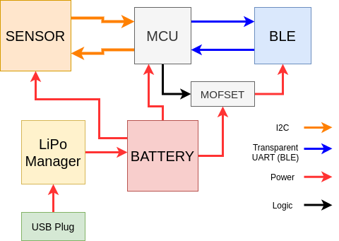
Components
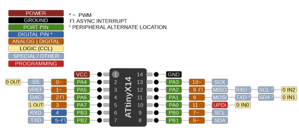
MCU - ATtiny 1614
I have worked only with ESP32 up to now so I wanted to deal with the ARM family and a small cheap chip. I chose the ATTiny1614 which has the capactiy I needed for this assignment :
- I2C for the sensor communication
- Serial for the communication with the BLE chip
- At least 1 ADC for the battery voltage measurement
- At least 1 digital output to control the MOFSET
- Sleep and Watchdog capacity for energy management
- Works at low voltage (important for the battery)
From the datasheet and internet I extracted the pin layout of the chip :

note : image was taken from rlocman website.
Sleep and Watch Dog
I studied the Sleep/Watchdog capacity in the datasheet and noted down the important information I learnt.
The philosophy of saving energy by putting an MCU to sleep is that there is a function called Watchdog which is basically a ‘timer + reset’ function. A timer is set and when it reaches the limit it resets the MCU. So if you want to check that your MCU is going of fine you set the watchdog, and a function that will periodically reset the watchdog timer before it reaches its limit. If your MCU freeze and your function cannot reset the timer then the watchdog reset the MCU. It is a good protection to avoid freezing. The diagram below explains it really well. (There is also the double window watch dog to avoid too early reset).

Step for sleeping the MCU
1. WatchDog/interrupt : choose how you MCU will be waken up with the WDT
    * Here I will not explain because I got a bit confused by some security (LOCK bit in WDT.STATUS) used
    to avoid change of the WDT. But the registry used are WDT.STATUS
    and WDT.CTRLA.

- SMODE : Choose the sleeping mode by changing the sleep registry. > SLPCTRL.CTRLA &= (b10 << 1);
- SEN : Activate the Sleep enable bit in the sleep registry (SLPCTRL.CTRLA) > SLPCTRL.CTRLA |= 0b1;
- Execute the sleep function.
 I could not find how to do it.

BLE chip
For the BLE I have the choice between the chips presented in the table below.
Note : not all of them are Bluetooth because they were mixed, but still I put all what we have for further reference.
| Name | BLE112-A | BL652-5A | RN4871 1904 | RN4871 2002 | TFB-BTI | MRF24J40MA |
|---|---|---|---|---|---|---|
| Picture |  |
 |
 |
 |
 |
|
| Technology | BLE | BLE | BLE | BLE | RF | RF |
| Extra info | QOQ BLE112 | SQGBL652 | V/RM118NB | V/RM118NB | 5969A-BTI | REV3 |
| Size | +++ | ++ | + | + | + (smallest) | ++++ (biggest) |
| Soldering | |
|
|
|
 |
|
Finally I chose the RN4871 for the following reasons :
- It has BLE 5.0 capacity
- It will be reasonably easy to solder
- The documentation provide good schematics
- It works at low voltage for the battery
For this chip two documents are really useful :
- The datasheet of course.
- The documentation for serial commands.
- I also took inspiration from Jorris Navarro documentation.
From the datasheet I took the following recommandation for the PCB and the Schematic.


The full name is
- RN4871 : 71 is for the packaging (here Ceramic Chip Antenna)
- 2002 : I do not know but the 2002 is BLE 5.0 and 1094 is BLE 4.2
- V : temperature range (various here -20ºC to +70ºC)
- RM : Radio Module
- 118NB : Firware version
Danger
After having worked with this chip and reading a lot about it I would not recommand to use it because it is really unstable and has firmware issue which provok an issue known as %UnknownDevice% issue. It happened to me when flashing the ATTiny with the chip on the same board. To improve the behavior the following circuit is recommanded in the datasheet to cut the power before the voltage gets too low.

Note
After analysis of how to mount the chip on my board I had a lot of doubt
concerning the interaction of the TX/RX between my FTDI connector, the ATTiny,
the RN4871.
I started a design with jumper to choose which branch to connect and also saw
a way to prioritize on branch over another by using resistors as explained
here http://www.billporter.info/2011/06/26/how-to-add-multiple-uart-connections/comment-page-1/.
I fiannly used the helloboard design from Niel.
Design of the RN4871 helloboard from Niel.

LiPo Manager
I had the choice between the two following components :
- MCP7383
- MAXISSSEZK
I chose the MCP7383 because I saw several projects using it and the datasheet has good explanation on how to mount it as shown in the picture below.

Usually what can be expected from a LiPo charger is :
- Suveying battery voltage during charge to avoid over charging
- Charging curve (Current function of voltage)
- Cut battery power if discharge is too important
In my case I had no component available to provide the third point. Being a small board for assignment I did not look for a component having this capacity but at least I learnt it exists.
SHT35 Sensor
The sensor I will use is called SHT35
From its datasheet I took the followign diagram to know how to use/mount it on my board.

Warning
I design the whole pcb with this footprint but I realized when trying to do the routing that the space between the pads does not allow to use a regular 1/64in end mill. As I was running a bit out of timeI decided to use the component already mounted on a board.

I used the library arduino-sht to read the sensor’s data. The library comes with Arduino IDE. I tried several before this one. This is the one that I liked the most.

Battery
I do not have much to say here execpt that the battery I used was 220mAh and when testing it on the board I could power the ATtiny but not the sensor.
I tried with a bigger battery (720mAh) and it worked fine.
This is probably due to the peak of current when reading the sensor value which uses I2C capcity of both the sensor and the ATTiny and the activation of the sensor.
This issue might be corrected by using a capacitor as energy buffer.
Maybe in another project  .
.
Autonomous sensor board Design
All that said I took some extra decision for the board design :
- BLE chip on hello board
- SHT35 on hellboard
I ended up with the following schematic.

And here is the board after soldering the components.

I tested that my MOSFET was working correclty by manually setting it’s gate to ground and it worked ! On the picture below one can see that when the Gate is link to the pull up the voltage on the BLE pins is 0V. But when I manually pull the Gate to ground the MOSFET acts as a closed switch as desired.


My understanding of transistor (Thanks Oscar!)

The testing setup with the Autonomous board, the ESP32 and the raspberrypi.

Having the board is nice, but now I have to make it work.
Let’s talk BLE
The idea of having the BLE cheap is to use it in the “Transparent UART” mode which means that when the ATtiny sends instruction through Serial, the RN4871 chip will send the information via the BLE protocol to whoever is here to listen.
What is BLE
The Arduino IDE comes with a range of example with the BLE library for ESP32. To learn how to use it I took some examples and :
- Studed the library itself
- Read the amazing documentation of Kolban
Long things short, the BLE is a modification of the original Bluetooth protocol meant for short distance, low weight communication for IoT. The idea is to avoid long connected states and privilege sending package of data over short period of time.
A diagram you find in Kolban’s documentation resumes pretty well the structure of the package (Important to know what we are doing afterward).

Each device has at least (in normal cases that i know of)
- An address in the form “04:91:62:9c:09:07”
- A service
- A characteristic that belong to the service –> where the data is
- A characteristic descriptor
Then we have usually two player
- The Server : which hosts the data
- The client : which needs the data
How to setup the RN4871
The commands to do it are not too complicated but you have to follow some important rules
I will describe the exact way I followed to have the chip working because I had lot of trouble.
1- Start with the hello board
2- Run the following command in the bash
> python -m serial.tools.miniterm /dev/ttyUSB0 115200
3- Type the following exacts keys :
$$$ ++Enter++ // To enter the command mode
+ ++Enter++ // Toactivate the ECHO ON
SS:C0 ++Enter++ // To activate transparant UART
R,1 ++Enter++ // To Reboot (must be done after each SET command
$$$ ++Enter++ // New cycle so reactivate the CMD mode
+ ++Enter++ // ECHO ON
S-,AdrienBLE ++Enter++ // TO change the name
I have seen here https://github.com/nkolban/esp32-snippets/issues/144 that the UUID cannot be too big otherwise is provokes the Guru crash
After a lot of issue I finally say the >CMD appear –> HAPPINESS

Let’s broadcast
Here again I will sum up my adventures to the following advice
Warning
The Transparent UART (of the RN4871 at least) has those two specificities
-
It sends the UART message in packets of 20 bytes max –> It means you have to either make small paackages of data or to manages the receive data on the client side
-
It does not advertise its serices but NOTIFIES –> It means that if you use the BLE_client example as such from the Arduino IDE it will not work. I modified the code as follows to start the connection based on the MAC address match instead on the Advertized service (as the RN4871 does not advertize).
1 2 3 4 5 6 7 8 9 10 11 12 13 14 15 16 17 18 19 20 21 22 23 24 25 26 27 28 | |
Before this modification I was getting the error presented below due to (I think) I tried to access information that did not exist. It provoked ESP32 continuous reset.

??? info “UART Documentation for RN4871 Here is the explanation in the documentation where it is stated that the RN4871 notifies instead of advertize.

I also would like to thank Kolban for the library and CLDiego and chegewara who helped me to find the solution on the Github repo of the library :https://github.com/nkolban/esp32-snippets/issues/1078.
The first message I received was of course “Hello” but on my cell phone.
I mounted the following setup : - RN4871 connected to ESP Serial to receive information - My cellphone reads the information from the RN4871
On the left the setup, in the middle the ESP32 sending “Hello” through the serial, on the right my cell phone receiving the message.


Once I had the proof that the RN4871 can emit properly and be received here is the reception of the message from the Autonomous sensor board to the ESP32. It seems a simple message but it was a lot of bluetooth debugging as explained before.

The reception is not really clean because there is still debug messages and I have weird characters, but still it works. For the interface week I will improve it.
Here is the system working on its own !
ESP32 to RasPi via Wifi
Now that I can receive the information I need into my ESP32 I want to share them to the Raspberry Pi for the interface week.
So I used the example I worked on during the workshop to send the information. It is based on the example mentionned at the beginning of this page plus :
- The publish part is included in the Bluetooth “OnNotify” Callback.
- I light a LED when receiving the BLE package
- I light a LED when I send the wifi package
- I connect the wifi before the bluetooth
- I send the data in form of a Jason string
Warning
So that the code fits in the ESP32 one has to use the option Partition Scheme = Minimal SPIFFS
At the moment I write this page, even if the connection works, I have not finalized the data pipe fully because I am still trying to figure out the best one with the following questions :
- Should I do the Jason serialization in the ATtiny or the ESP32 ?
- How should I form the jason package ? (sensor name based on mac address for example ?)

The loop is complete !
Objectives reached ?
Well, better than expected, and i learnt A LOT of things this week.
- Read Temperature and Humidity through I2C
- Information sent via UART BLE to ESP32
- Information sent from ESP32 to RaspberryPi via Wifi
- Battery powered
- Board can charge battery
- Use Sleep/Watchdog of ATTiny for energy saving
- Use ATTiny internal voltage reference for battery voltage measure for battery protection
- MOFSET used to switch on/off the bluetooth chip
Wall of Fame
To rest a little bit after the documentation, some interesting pictures I took.
I planned to use a 2kOhm resitor as a bridge but the one available was much smaller than my planned footprint. So I did my best with 2x1kOhm :

I had a lot of trouble flashing my ATtiny and as I did not trust my board, I did a bare metal flashing !

… and the failure came from .... the FTDI board !
Files
Testing protocoles
- ESP32-ESP8266 : I2C communication Both Directory and Managed node are in the same code, one has to comment/uncommand the part to flashed.
- ESP32 - MQTT : Wifi communication
AutonomousSensorBoard
-
To reproduce the Electronic
-
For the software
Links
thethingsnetwork.org : web about networks