8. Embedded programming
Group assignment
As one will see in my personal assignment I worked on a lot of possible way to interact and flash ESP32. I gathered all the information from the boards we as a group worked in a table to see what are the possible and most effective way to program micro controllers.
| Board | Chip | ToolChain | WorkFlow/IDE | Framework/Libraries | Connection | Code | Time to compile & Flash | Sketch memory | Global variable memory | Comment |
|---|---|---|---|---|---|---|---|---|---|---|
| MyBarduino | ESP32 | Esptools | ArduinoIDE | Arduino | USB-FTDI | Arduino | 10s | 198kb | 13kb | |
| MyBarduino | ESP32 | Esptools | ArduinoIDE | ESP library | USB-FTDI | C | 10s | 197kb | 13kb | |
| MyBarduino | ESP32 | Esptools | ESP-IDF | ESP-IDF | GPIO | C | 10s | 155kb | 24.1kb | |
| MyBarduino | ESP32 | Esptools | PlatformIO | Arduino | GPIO | Arduino | 10s | 266kb | 13kb | |
| MyBarduino | ESP32 | Esptools | MicroPython | MicroPython | GPIO | Python | 10s | N/A | N/A | |
| MyBarduino | ESP32 | Esptools | MicroPython | MicroPython | USB-FTDI | Python | 10s | N/A | N/A | |
| MyBarduino | ESP32 | Esptools | MicroPython | MicroPython | WebREPL | Python | slow | N/A | N/A | |
| Arduino UNO | 328p | Arduino AVR | ArduinoIDE | 674bytes | ||||||
| Lilytiny | ATtiny85 | Arduino AVR | ArduinoIDE | |||||||
| Arduino PRO Mini | 328p | Arduino AVR + FTDI | ArduinoIDE | |||||||
| Arduino PRO Micro | 32u4 | Arduino AVR | ArduinoIDE | |||||||
| Leonardo | 32u4 | Arduino AVR | ArduinoIDE | |||||||
| LilyPAD | 32u4 | Arduino AVR | ArduinoIDE | |||||||
| ATTINY 45 | FLEX | Arduino AVR + ISP | ArduinoIDE | |||||||
| TEENSY | Custom TEENSY ARM | TEENSYDUINO (Arduino Modified) |
For each point of the table I can note the following as learning points :
-
Workflow : lots of workflows are available for all the board. One should choose the one he feels confortable with because at our programming level there is no much differences. If I had to choose one for ESP-32, ESP-IDF is nice because it fits my chip (ESP32) but Platformio interaction in the terminal is really smooth. So that would be one of those.
-
Framework : This is the environment of library you work with. In my case I worked a lot with Arduino and bare C with register interaction. Python was also involved. When working with AVR chip there is sense to use bare C to save on space. But when working with ESP32 it seems that even working only with C there is no much memory to save on because “side libraries” are to be loaded on the chip and the blink code will be a tiny part of it.
-
Connection : We saw several ways to connect to our boards ranging from USB-FTDI to Raspberry pi 4 GPIO pins passing by direct wiring connection on flexible board. I enjoyed working with Rpi4 GPIO pins as it avoid using an FTDI board and free a USB port.
-
Time to compile and flash : For ESP32 I noted that the flashing time is longer than for other board probably due to the extra features (wifi, bluetooth etc…). Also when working with ESP-IDF, the first build is really slow and I could see a lot of library were loaded.
-
Memory usage : For the ESP32 we were not capable to reach the value of AVR processor (factor of 1000). This is probably due to the programs needed to run all the extra features of the board. Also with Pyhon we could not fully evaluate the weight as the main part of the code is MicroPyhon which is loaded via the firware. The we only send the python code which has a low weight (few bytes)
Memory analysis
For information I place the memory output of each compiled file. ESP32_blink_01_FullArduino - Arduino 212.0 kb Sketch uses 198932 bytes (15%) of program storage space. Maximum is 1310720 bytes. Global variables use 13276 bytes (4%) of dynamic memory, leaving 314404 bytes for local variables. Maximum is 327680 bytes.
ESP32_blink_02_PinTranslation - Arduino 218.3kb Sketch uses 204892 bytes (15%) of program storage space. Maximum is 1310720 bytes. Global variables use 13436 bytes (4%) of dynamic memory, leaving 314244 bytes for local variables. Maximum is 327680 bytes.
ESP32_blink_02_PinTranslation_minicode - Arduino With delay : 211.1kb Sketch uses 198008 bytes (15%) of program storage space. Maximum is 1310720 bytes. Global variables use 13104 bytes (3%) of dynamic memory, leaving 314576 bytes for local variables. Maximum is 327680 bytes. No delay : 210.0 kb Sketch uses 197802 bytes (15%) of program storage space. Maximum is 1310720 bytes. Global variables use 13092 bytes (3%) of dynamic memory, leaving 314588 bytes for local variables. Maximum is 327680 bytes.
Blink Adrien - On ESP-IDF With/Wihout delay:182.7kb 24.1kb : 0x1000 /home/pi/Documents/00_Projects/01_FabAcademy/repository/adrien-laveau/docs/files/week08/blinkAdrien_ESP-IDF/build/bootloader/bootloader.bin 155.5kb : 0x10000 /home/pi/Documents/00_Projects/01_FabAcademy/repository/adrien-laveau/docs/files/week08/blinkAdrien_ESP-IDF/build/blinkAdrien.bin 3.1kb : 0x8000 /home/pi/Documents/00_Projects/01_FabAcademy/repository/adrien-laveau/docs/files/week08/blinkAdrien_ESP-IDF/build/partitions_singleapp.bin
Personal assignment
In the documentation I will present this week I experienced interacting with my ESP32 in the following ways.
- Arduino IDE
- Arduino pure C
- make process - ESP-IDF
- plateform IO
- Raspberry : flash with GPIO
- Micro Python
During the lectures we learnt that programming a micro-processor consists in several major steps :
- Writing code
- Preprocessing the code
- Compiling the code
- Link the compiled code with eventual libraries
- Convert it to binary
- Flash it in the microprocessor
Those steps can be done in A LOT OF different ways. During this week I will try to review some of them and understand the difference of each method. I will also try to remove the “abstraction layers” as much as I can to fully understand each process.
During Week6 Electronic Design I created a board based on the ESPRESSIF microchip. So my exmperimentations will be based on this board. I will use its documentation to go through the week :
ESP32 specificity
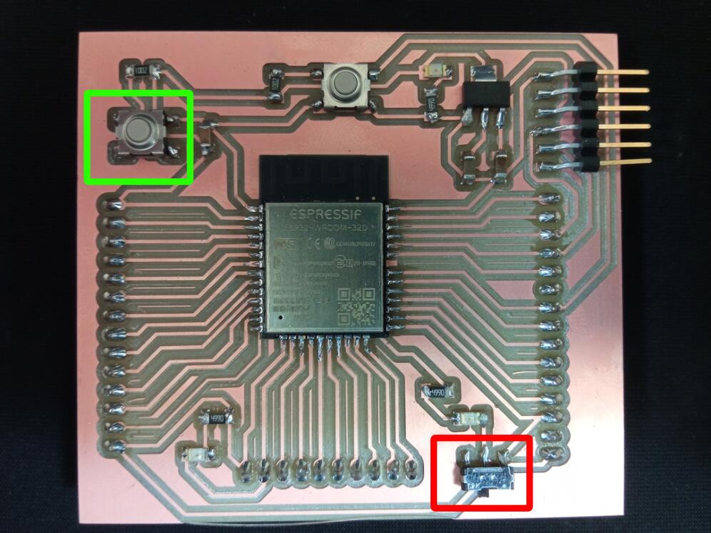
Flash mode
In order to be flashed the ESP32 has to be set in boot mode. To do so in the design we introduced 2 elements : * A microswitch to change the mode –> red * A button to reset the board (kind of unplug-plug the power source) –> green
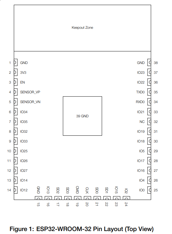
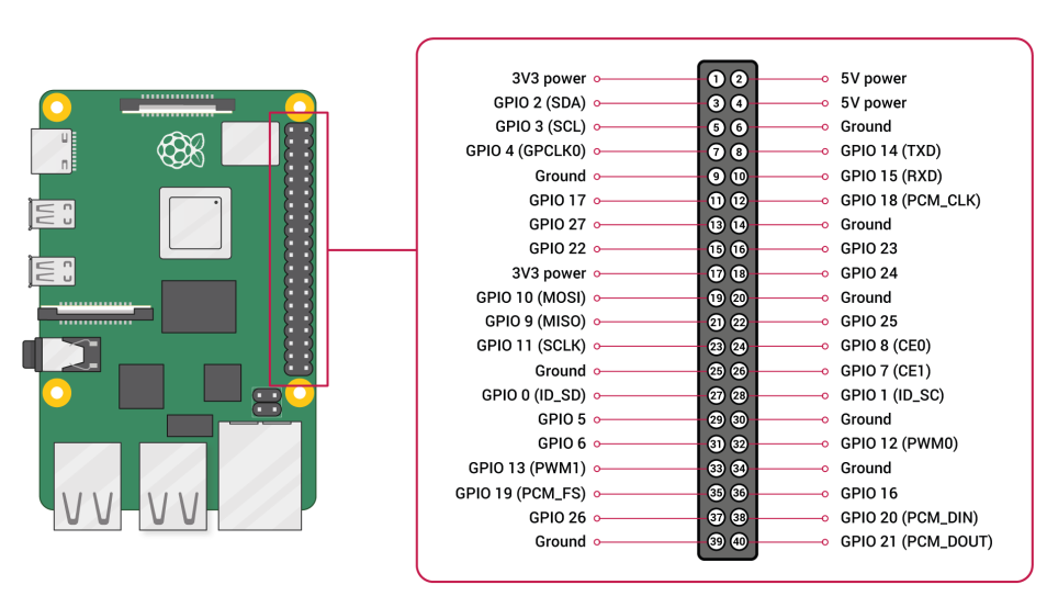
PinOut
My board is inspired on the Barduino Project from FabLab Barcelona. For this week I will use their visual pinout.

Datasheet Analysis
Introduction
The ESP32-WROOM-32 is a microcontoller that comes with extra features such as :
- Wi-Fi
- Bluetooth
The chip itself is based on a chip called ESP32-D0WDQ6. It has 2 CPU and the frequency can be adapted from 80MHz to 240MHz. And in case one is working on a low power requirement project, a co low-power co-processor can work instead of the CPU to do low power tasks (it is getting complicated …)
The ESP32 can manage a lot of peripherals such as :
- SD Card interface
- Ethernet
- SPI
- UART
- I2S
- I2C
Thoses protocols are interesting because I know that some LCD screen require I2C protocol to work. Also my final project might need to store data on an SD card if no internet is available.
Functional description
The ESP32 has 2 processors called “low-power Xtensa 32-bit LX6”.
The 32 bit information is important because it will impact our way to deal with registers.
From ADAFRUIT website documentation
I found out that the use the harvard-processor-architecture which is known
to be better than the newmann one as data and program are stored in
different memories and so avoid the “newmann bottle neck”.
The CPUs are called :
- PRO_CPU : protocol CPU
- APP_CPU : application CPU
Memory
The table below shows the memory available in the chip. Before giving the information I will try to explain with my words the use of each memory and to reproduce a memory map. Program memory (interesting link from microchip
- ROM : Read only memory -> when creating the chip
- EPROM : Erasable Programable Read Only memory -> need a window in the casing to be flashed with light !
- EEPROM (flash) : Electrically Erasable Programable Read Only Memory -> when flashing the chip “by wire”
I start to think that we say “flashing a microcontroller” because when program the Flash/EEPROM memory (nor the ROM neither the EPROM)
Internal Memory
| Memory type | Quantity | Description |
|---|---|---|
| ROM | 448kB | For the base code of the chip that will not be changed |
| SRAM | 520kB | Faster and more expensive than DRAM. For cache and internal register |
| SRAM in RTC - RTC FAST | 8kB | |
| SRAM in RTC - RTC SLOW | 8kB | |
| eFuse | 1kB | Used as One Time programming to set up specific infor,ation in the chip |
External memory
| Memory type | Quantity | Description |
|---|---|---|
| SPI Flash | 4Mb | Connected to GPIO6,7,8,9,10,11. They cannot be used an normal GPIO |
Memory mapping
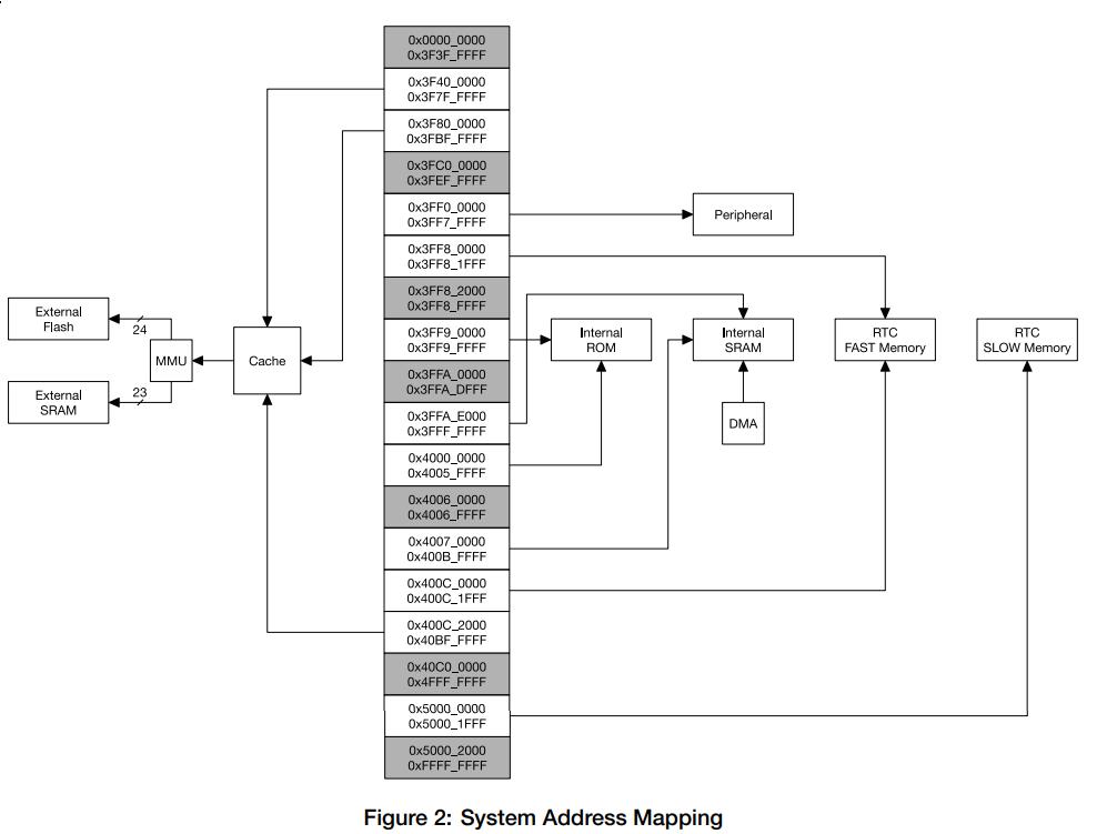
Each CPU has a 32bit address space. It means an address is defined by a word of 32 bit long (that is 4,2 billions possible addresses! - 4Gb)
Cool video on how to desacralize memory address and physical location of the bit
Accessing the GPIO
What I am going to describe below took me around 15hrs to understand and to reach my goal of bliking the led without Arduino IDE. It was a first for me to read so deeply a datasheet and I want to share what I learnt. No everything is clear in my hea at the moment, but what I learnt allows me to fully remove Arduino code.
Peripheral Address Mapping - GPIO
Extract from, table 1-6 of datasheet.
All GPIO addresses related register are stored in the range of addresses
presented in the table below.
One concret example of that is the following.
In the C code of the ESP32 library for Arduino one can find the following line :
#define GPIO_OUT_REG (DR_REG_GPIO_BASE + 0x0004)
#define DR_REG_GPIO_BASE 0x3ff44000
Which means that :
- GPIO_OUT_REG = 0x3ff44004
- DR_REG_GPIO_BASE = 0x3ff44000
Both thoses values are within 0x3FF4_4000 and 0x3FF4_4FFF. It seems a small info but I was pretty happy to be able to “use” some info of the datasheet (table below).
| Bus Type | Boundary address | Size | Target |
|---|---|---|---|
| Data | from 0x3FF4_4000 to 0x3FF4_4FFF | 4 KB | GPIO |
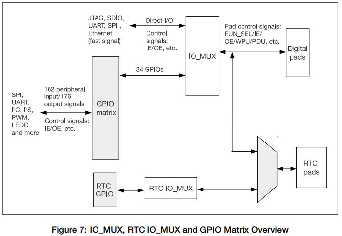
Now how do we really access the GPIO. Well the datasheet contains a paragraph called “4 IO_MUX and GPIO Matrix” in which it explains the workflow to link peripherals (every sensor including GPIO handle by the chip and PADS (also called pins).
Definition (from what I understood)
Pads : physical pins Peripherals : all the sensors and GPIO capacity of the chip
The goal of this part is to route the proper peripherals in the proper pad and vice-versa. The chapter is broken in 2 parts which explain the diagram below depending if we are looking for an input or an output.
Peripheral Input via GPIO Matrix Below one can see that the function (register) GPIO_FUNCy_IN_SEL will link Peripheral signal Y with the GPIO set in its bit word.
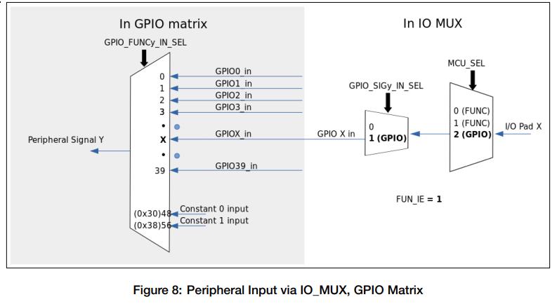
Simple GPIO Input - as explaind in datasheet
The GPIO_IN_REG/GPIO_IN1_REG register holds the input values of each GPIO
pad.
The input value of any GPIO pin can be read at any time without configuring
the GPIO Matrix for a particular peripheral signal. However, it is necessary
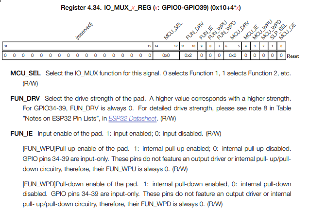
to enable the input in the IO_MUX by setting the FUN_IE bit in the
IO_MUX_x_REG register corresponding to pad X, as mentioned in Section 4.2.2.
Peripheral Output via GPIO Matrix
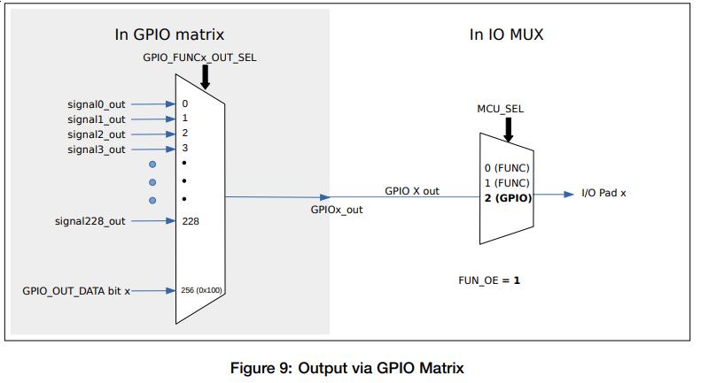
Simple GPIO Output - as explaind in datasheet
The GPIO Matrix can also be used for simple GPIO output – setting a bit
in the GPIO_OUT_DATA register will write to the corresponding GPIO pad.
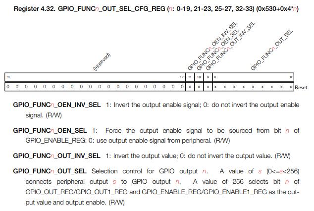
To configure a pad as simple GPIO output, the GPIO Matrix GPIO_FUNCx_OUT_SEL
register is configured with a special peripheral index value (0x100).
To make it work I had to use the following functions found in soc.h
(Arduino ESP32 library) :
// Set GPIO_FUNCx_OUT_SEL at 0x100 to confirm it is a GPIO Output
// One cannot just use the equality you have to use REG_WRITE and REG_WRITE
// Activation of the GPIO function
REG_WRITE(GPIO_FUNC18_OUT_SEL_CFG_REG, 0b100000000 | REG_READ(GPIO_FUNC18_OUT_SEL_CFG_REG));
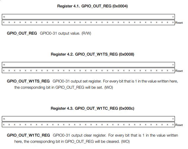
// Set the GPIO_OUT_REG registry to 1 at bit 18 to light up the LED using
// either GPIO_OUT_REG or GPIO_OUT_W1TS_REG
REG_WRITE(GPIO_OUT_REG, ((1<<18) | REG_READ(GPIO_OUT_REG)));
or
REG_WRITE(GPIO_OUT_W1TS_REG, ((1<<18) | REG_READ(GPIO_OUT_W1TS_REG)));
// Set the GPIO_OUT_W1TC_REG registry to 1 at bit 18 to switch off the LED
// This command is clearing the output register and has to be set at 1 not 0 as
// one (me...) would think.
REG_WRITE(GPIO_OUT_W1TC_REG, ((1<<18) | REG_READ(GPIO_OUT_W1TC_REG)));
Below one can see the binary representation of both registry :
Even deeper
Another level of abstraction can be removed by using directly the functions REG_WRITE and REG_WRITE in C style.
(*(volatile uint32_t *)(GPIO_OUT_REG)) = (((1<<18) | GPIO_OUT_REG));
Instead of
REG_WRITE(GPIO_OUT_REG, ((1<<18) | REG_READ(GPIO_OUT_REG)));
But as I do not understand fully the volatile concept I let it aside for the moment.
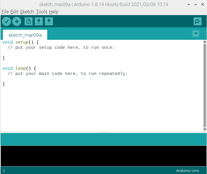
Arduino
Arduino IDE
The Arduino IDE is more than a tool to work with Arduino.
It is a C based framework that does a lot of things for you.
Basically, all the steps mentionned earlier can be done in 1 click within
the IDE.
And the great things is that if someone has created the code to deal with your chip and board, you can program
it using Arduino IDE.
Below I will show you how to install Arduino on the Pi and take and a simple blink example and remove as much abstraction layer as possible.
Install it on Rpi4
- Go to Arduino Official webpage
- Download the Arduino IDE for ARM
-
Then install it (following instruction from this web
cd
cd Downloads
ls (to confirm it's here)
tar -xf arduino-####-linuxarm.tar.xz (for me nightly-linuxarm.tar.xz) -> will extract the package
sudo mv arduino-nighlty-linuxarm.tar.xz /opt --> move the files to the **opt** folder
sudo /opt/arduino-nightly-linuxarm.tar.xz/install.sh --> will install the IDE
You can now enjoy the Arduino IDE :)
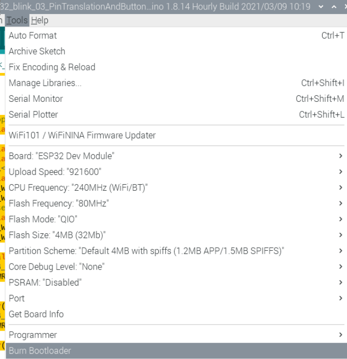
The configuration I use for the ESP32 is the following one :
Coding & Flashing with Arduino
Now I will work on various way to flash my ESP32 using Arduino IDE.
- Full Arduino : pure Arduino code using the whole library
- Direct PIN interation - LED only : I translate the Arduino command to pure C
- Direct PIN interaction - LED and Button : Now everything is in C !
First iteration with Arduino IDE. I have just added some interaction with the button of my board compared to the basic example.
1 2 3 4 5 6 7 8 9 10 11 12 13 14 15 16 | |
Danger
To reach that point I literraly needed 10h of work… It is based on the research presented in the datasheet analysis. After doing this work I would to pay my respect to the persons who worked on the abstracion layers :)
1 2 3 4 5 6 7 8 9 10 11 12 | |
Now I will work at adding the button using register interaction to remove Arduino libraries.
In this part I have two functions
* The blinking LED on port 18
* A button commanded LED on port 13
For the LED 13 I spent a lot of time because it was not working even using the exact same command as for LED on pin 18. It is because the pin 13 does not act GPIO as default. One can see in the table below (extract from datasheet) that the GPIO 13 has :
- MTCK as function 1
- GPIO as function 2
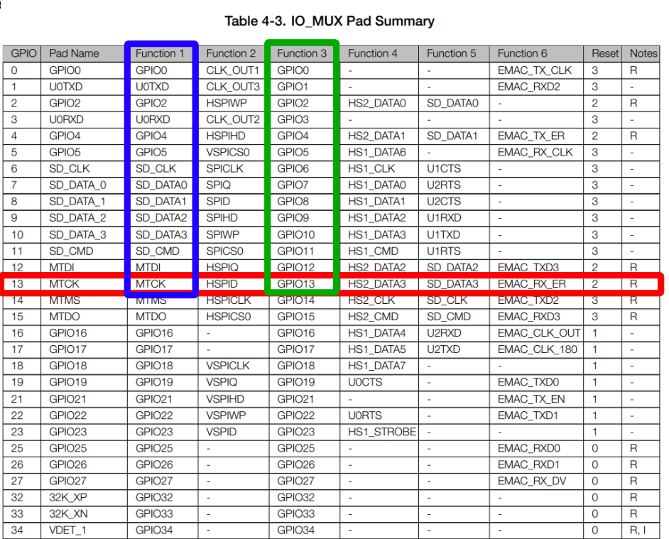
So you have to set function 2 in IO_MUX_GPIO13_REG and then set the GPIO as OUTPUT.
Set bit 12-13 at 10 (function 3 = 0b10)
REG_WRITE(IO_MUX_GPIO13_REG,(~( 1 << 12 ) & REG_READ(IO_MUX_GPIO13_REG)));
REG_WRITE(IO_MUX_GPIO13_REG,(( 1 << 13 )| REG_READ(IO_MUX_GPIO13_REG)));
REG_WRITE(IO_MUX_GPIO13_REG,(~( 1 << 9 ) & REG_READ(IO_MUX_GPIO13_REG)));
The information comes from the datasheet
Here is the final code with the higlighted line dealing with what is explained before.
Also for reading the button state and using it in an IF statement I use both Bit shifting operators << and >>.
- REG_READ(GPIO_IN_REG) >> 19 –> shifts my bit 19 to position 0
- (1<<0) & REG_READ(GPIO_IN_REG) >> 19 –> check value of bit 1 using & operator
- (1<<0) & REG_READ(GPIO_IN_REG) >> 19 == 0 –> comparing the result 1 or 0
1 2 3 4 5 6 7 8 9 10 11 12 13 14 15 16 17 18 19 20 21 22 23 24 25 26 27 28 29 30 31 32 33 34 35 36 | |
Sketch uses 204892 bytes (15%) of program storage space. Maximum is 1310720 bytes. Global variables use 13436 bytes (4%) of dynamic memory, leaving 314244 bytes for local variables. Maximum is 327680 bytes.
Below is the full code of the “Direct PIN Interaction - LED only” tab. One can notice the extensive use of the Serial.Print function for debugging. It was really interesting to check the bit state of the registry and confirm that some modification were properly done. Also you can check how the MC interprets the binary operations (<<, >>, && etc…)
Using Serial with Arduino IDE
-
Activate the Serial protocol
Serial.begin(115200);
-
Print something to the serial
Serial.println(“Something”) //Text information Serial.println(Boolean register,BIN) //Add the “BIN” tag to see it in binary
-
Check the serial output using miniterm (you might have to press the “reset” button)
python -m serial.tools.miniterm /dev/ttyS0 115200
Danger
Some registry are “WO = write only” and cannot be read, and return 0. I did not know that and got confused a lot while debugging. Take care !
void setup() {
  Serial.begin(115200);

  Serial.println("STAAAART");
  Serial.println(REG_READ(GPIO_FUNC18_OUT_SEL_CFG_REG),BIN);
  REG_WRITE(GPIO_FUNC18_OUT_SEL_CFG_REG, ~0b111111111 & REG_READ(GPIO_FUNC18_OUT_SEL_CFG_REG));
  Serial.println(REG_READ(GPIO_FUNC18_OUT_SEL_CFG_REG),BIN);
  REG_WRITE(GPIO_FUNC18_OUT_SEL_CFG_REG, 0b100000000 | REG_READ(GPIO_FUNC18_OUT_SEL_CFG_REG));
  Serial.println(REG_READ(GPIO_FUNC18_OUT_SEL_CFG_REG),BIN);
  Serial.println(REG_READ(GPIO_ENABLE_REG),BIN);
  Serial.println(( 1 << 19),BIN);
  Serial.println( 1 << 19 | REG_READ(GPIO_ENABLE_REG),BIN);

  Serial.println(REG_READ(GPIO_ENABLE_REG),BIN);
   REG_WRITE(GPIO_ENABLE_W1TS_REG,((1<<18)| REG_READ(GPIO_ENABLE_W1TS_REG)));


}

void loop() {
  Serial.println("bonjour");


   Serial.println(REG_READ(GPIO_OUT_REG),BIN);
   REG_WRITE(GPIO_OUT_REG, ((1<<18) | REG_READ(GPIO_OUT_REG)));
   Serial.println(REG_READ(GPIO_OUT_REG),BIN);


delay(1000);

   Serial.println(REG_READ(GPIO_OUT_W1TC_REG),BIN);
   Serial.println(REG_READ(GPIO_OUT_REG),BIN);
   REG_WRITE(GPIO_OUT_W1TC_REG, ((1<<18) | REG_READ(GPIO_OUT_W1TC_REG)));
   Serial.println(REG_READ(GPIO_OUT_W1TC_REG),BIN);
   Serial.println(REG_READ(GPIO_OUT_REG),BIN);

   delay(1000);


}
ESP-IDF Framework
Install and Use ESP-IDF
Links used for this part :
The explanation below are copied from the weblink above which is an extract of the offical web page of Espressif
- Getting some packages needed for ESP-IDF
> sudo apt-get install git wget make libncurses-dev flex bison gperf python python-serial - Create base directory
> mkdir -p $HOME/esp32 -
Download binary Toolchain for the ESP32
ESP32 toolchain (32 and 64-bit) for Linux is available for download from Espressif website. Download this file, then extract it to the $HOME/esp.cd $HOME/esp32 wget https://dl.espressif.com/dl/xtensa-esp32-elf-linux64-1.22.0-61-gab8375a-5.2.0.tar.gz tar -xzf xtensa-esp32-elf-linux64-1.22.0-61-gab8375a-5.2.0.tar.gz export PATH=$PATH:$HOME/esp32/xtensa-esp32-elf/bin echo "export PATH=\$PATH:$HOME/esp32/xtensa-esp32-elf/bin" >> ~/.bashrc -
Get ESP-IDF from GitHub
Clone ESP-IDF using git clone command. Framework will be downloaded into $HOME/esp/esp-idf. I strongly recommend cloning the repository to local computer because it’s frequently updated and It’s good to keep it up to date.Install dependenciescd $HOME/esp32 git clone --recursive https://github.com/espressif/esp-idf.git export IDF_PATH=$HOME/esp32/esp-idf echo "export IDF_PATH=$HOME/esp32/esp-idf" >> ~/.bashrccd ~/esp/esp-idf ./install.shTo be run all the time
This will add the necessary path to the current terminal session
. $HOME/esp32/esp-idf/export.sh
-
Update framework ESP-IDF It’s a easy to keep framework ESP-IDF up-to-date with the following commands.
cd $HOME/esp32/esp-idf git pull git submodule update -
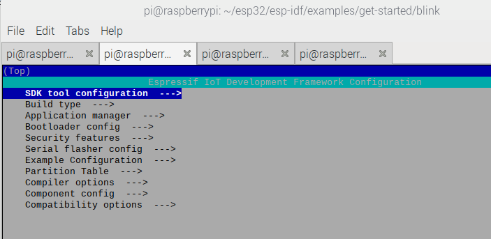
Compile “blinky” example Now you can test the toolchain. Compile one of the examples from directory $HOME/esp-idf/examples.
When using make for the first time a configuration menu appears which is the equivalent of the Arduino Tool menu where you can set up a lot of information such as the port for flashing, baud rate etc…cd $HOME/esp32/esp-idf/examples/get-started/blink make menuconfig makeThe second time you use make the menu does not appear. If you want to see it again you have to run ‘make menuconfig’ then ‘make’
-
Flash
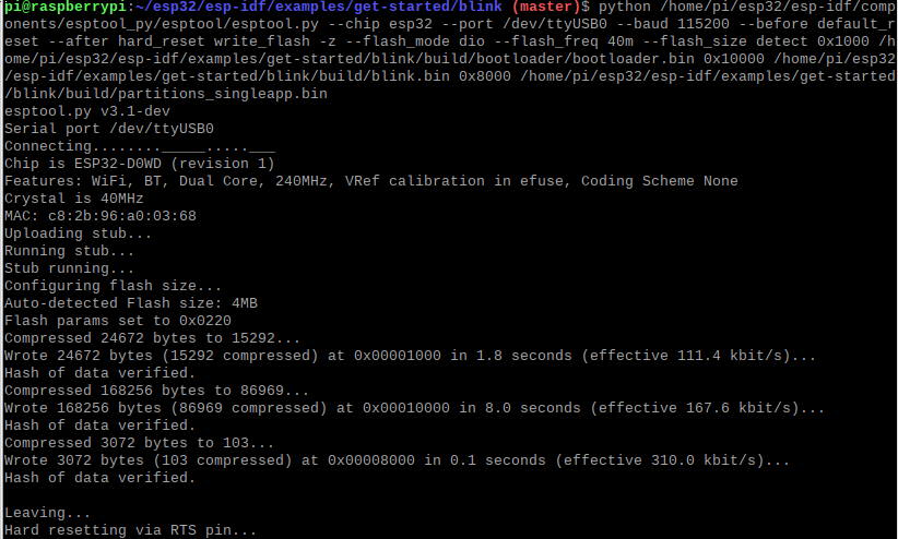
Once the code is compiled, the ‘make’ command tells you :
To flash all build output, run 'make flash' or:
python /home/pi/esp32/esp-idf/components/esptool_py/esptool/esptool.py
--chip esp32 --port /dev/ttyUSB0 --baud 115200 --before default_reset
--after hard_reset write_flash -z --flash_mode dio --flash_freq 40m
--flash_size detect
0x1000 /home/pi/esp32/esp-idf/examples/get-started/blink/build/bootloader/bootloader.bin
24kb
0x10000 /home/pi/esp32/esp-idf/examples/get-started/blink/build/blink.bin
164.3kb
0x8000 /home/pi/esp32/esp-idf/examples/get-started/blink/build/partitions_singleapp.bin
3kb
**Total 191.3kb**
From which the important informations can be seen :
- –chip esp32 : flashed chip
- –port /dev/ttyUSB0 : port where the board is plugged
- –baud 115200 : baud rate to be used
- your_path/blink.bin : the binary file to be flashed
The flash process is using in both Arduino and ESP-IDF the tool esptool.py v3.1-dev.
Adapt my Arduino C code to ESP-IDF
- Parenthesis everywhere
- USe int ‘app_main(void) {‘ instead of ‘int main(void) {‘
- Add the following libaries
#include <stdio.h>
#include "freertos/FreeRTOS.h"
#include "freertos/task.h"
#include "driver/gpio.h"
#include "esp_log.h"
#include "led_strip.h"
#include "sdkconfig.h"
Compare ISP-EDF and Arduino outputs
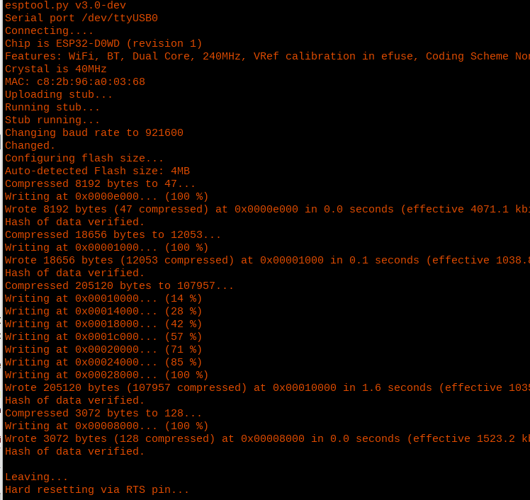
Arduino Output
Let’s strip down the commands.
python /home/pi/.arduino15/packages/esp32/tools/esptool_py/3.0.0/esptool.py
--chip esp32
--port /dev/ttyUSB0
--baud 921600
--before default_reset
--after hard_reset write_flash
-z
--flash_mode dio
--flash_freq 80m
--flash_size detect
0xe000 /home/pi/.arduino15/packages/esp32/hardware/esp32/1.0.5/tools/partitions/boot_app0.bin
8kb
0x1000 /home/pi/.arduino15/packages/esp32/hardware/esp32/1.0.5/tools/sdk/bin/bootloader_qio_80m.bin
18.2kb
0x10000 /tmp/arduino_build_345595/ESP32_blink_03_PinTranslationAndButton.ino.bin
200kb
0x8000 /tmp/arduino_build_345595/ESP32_blink_03_PinTranslationAndButton.ino.partitions.bin
3kb
**Total 229.2kb**
python /home/pi/.arduino15/packages/esp32/tools/esptool_py/3.0.0/esptool.py
--chip esp32
--port /dev/ttyUSB0
--baud 921600
--before default_reset
--after hard_reset write_flash
-z
--flash_mode dio
--flash_freq 80m
--flash_size detect
0xe000 /home/pi/.arduino15/packages/esp32/hardware/esp32/1.0.5/tools/partitions/boot_app0.bin
8kb
0x1000 /home/pi/.arduino15/packages/esp32/hardware/esp32/1.0.5/tools/sdk/bin/bootloader_qio_80m.bin
18.2kb
0x10000 /tmp/arduino_build_48376/ESP32_blink_01_FullARDUINO.ino.bin
194.4kb
0x8000 /tmp/arduino_build_48376/ESP32_blink_01_FullARDUINO.ino.partitions.bin
3kb
**Total 223kb**
Bare metal flashing (using ESP-IDF)
https://vivonomicon.com/2019/03/30/getting-started-with-bare-metal-esp32-programming/
“Bare metal flashing” could be done through ESP-IDF
Check that ESP tool chain is properly installed by checking the version
xtensa-esp32-elf-gcc –version
In the following folder lies bootloader_start.c which is the bootloader code. esp-idf/components/bootloader/subproject/main
call_start_cpu0 is the main function
Using xtensa-esp32-elf-nm build/bootloader/bootloader.elf we get where each part will be installed
… I leave it for a cold winter. I need a port I do not have. And I want to try more things.
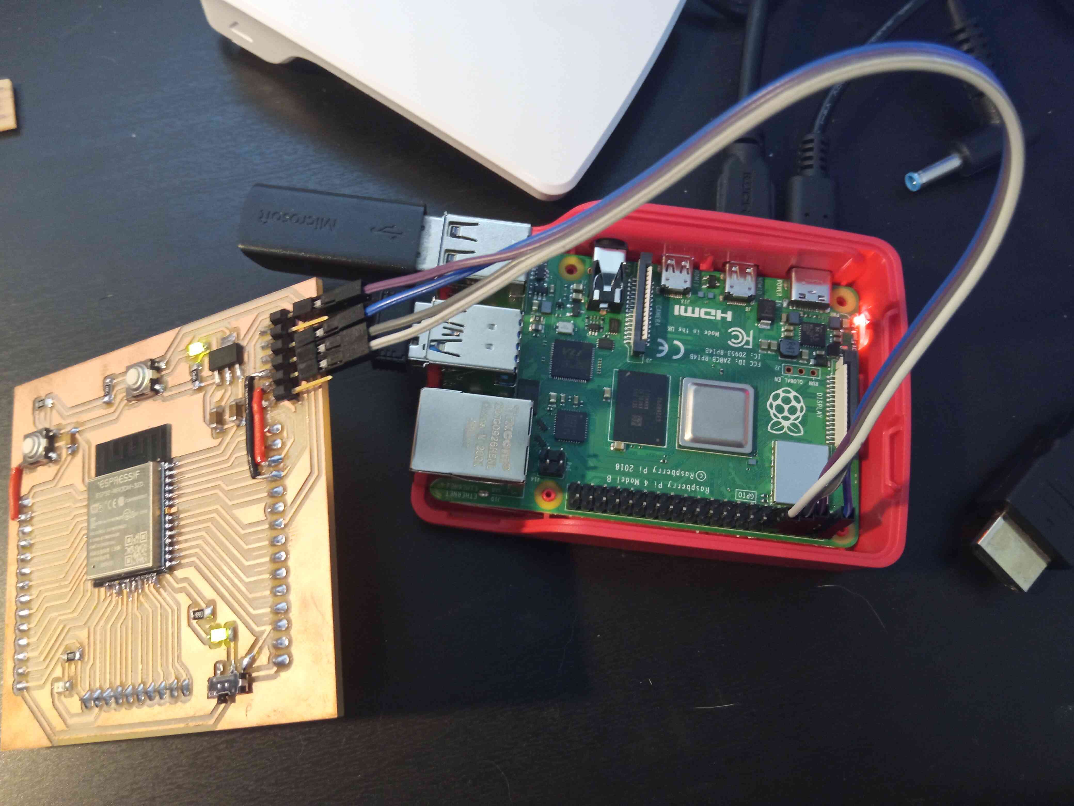
Flashing with Raspberry GPIO
This is pretty useful if you have no FTDI or UPDI. For UPDI an extra resistance would be needed between TX and RX and is not presented here. Once the wiring is done one should use /dev/ttyS0 instead of /dev/ttyUSB0 and that’s all !
Wiring
One should connect to the board using the following GPIO of the Rpi4 :
- 5V
- GND
- TX
- RX
Comparing the pin layout of both Rpi4 and ESP32 I matched my wiring. Afterward in all my script I just have to use ttyS0 instead of ttyUSB0.
And it works !
Micro Python
In this part I will try to use MicroPython and understand its advantages/disadvantages.
Downloadfirm ware
At https://micropython.org/download/esp32/ download the file adapted to your board.
For me : GENERIC : esp32-idf4-20210202-v1.14.bin
Install firmware
The following code line will guide you through the firmware intallation. Thoses steps have to be done everytime you use another system (Ex : Arduino, ESP-IDF…)
-
Download the flashing tool
pip3 install esptool
-
Put the board in prog mode & push the rest button
-
Erase the flash
esptool.py –port /dev/ttyUSB0 erase_flash–> can take a while
-
Press the reset button
-
Flash the board with the firmware
FTDI USBesptool.py –chip esp32 –port /dev/ttyUSB0 write_flash -z 0x1000 /home/pi/Downloads/esp32-idf4-20210202-v1.14.bin
FTDI GPIO
esptool.py –chip esp32 –port /dev/ttyS0 write_flash -z 0x1000 /home/pi/Downloads/esp32-idf4-20210202-v1.14.bin
First communication
I used several tool to communicate with the board flashed in Python. They are kind of light terminals.
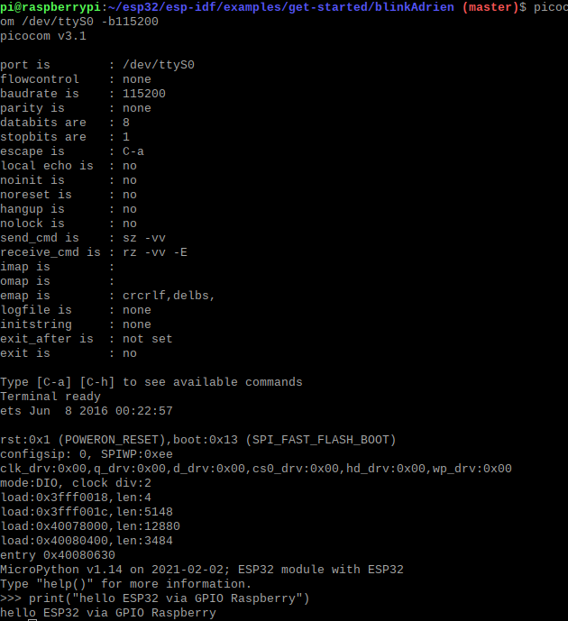
With Picocom
sudo apt-get install picocom
picocom /dev/ttyS0 -b115200 //Push the reset button to start
Use it like a normal python console. Below a simple hello worl test.
With miniterm
Use one of the following command depending on how is your board connected.
python -m serial.tools.miniterm /dev/ttyUSB0 115200
python -m serial.tools.miniterm /dev/ttyS0 115200
Over wifi WebREPL
To work over wifi some configuration steps needs to be put in place via wire.
-
Connect via wire
- With USB
picocom /dev/ttyUSB0 -b115200 // conect via wire first
- With Raspi4 GPIO
picocom /dev/ttyS0 -b115200 // conect via wire first
- With USB
-
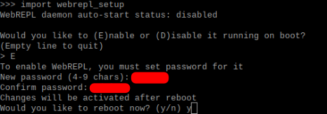
Run the webrepl setup. This function will guide you through the webrepl installation.
import webrepl_setup
-
Connect to the Access Point
Doing so would normally activate a Wifi Access-Point (AP). To which one should get connect to use the web interface. The access point is defined as follows :- ESSID : MicroPython-xxxxxx
- password : micropythoN
- IP : 192.168.4.1
-
OR setup via your home Wifi I do not know why but the acces point is not working in my case. So I configured manually the ESP32 to connect to my house wifi.
>>> import network >>> sta_if=network.WLAN(network.STA_IF) >>> ap_if=network.WLAN(network.AP_IF) >>> sta_if.active() False >>> ap_if.active() False >>> ap_if.ifconfig() ('192.168.4.1', '255.255.255.0', '192.168.4.1', '0.0.0.0') >>> sta_if.active(True) True >>> sta_if.connect('MyESSID', 'MyWfifiPassword') >>> sta_if.isconnected() True >>> ap_if.ifconfig() ('192.168.4.1', '255.255.255.0', '192.168.4.1', '0.0.0.0') >>> sta_if.ifconfig() ('192.168.0.31', '255.255.255.0', '192.168.0.1', '212.166.211.2') -
Access WebREPL To finally access the ESP32 via wifi once the connection is live you can go to this URL (http://micropython.org/webrepl/#IP.IP.IP.IP:8266/), the IP was detected using ap_if.ifconfig() in point 4. The IP of your chip will depend if your are using access point or home wifi.

Do Something !
Now that we are connected we can start doing stuff !
Direct communication
Either through wifi, picocom or miniterminal we can send commands to the ESP32.
Connections
Quick reminder to connect to ytour board with MicroPython
- Picocom
picocom /dev/ttyS0 -b115200
- Miniterm
python -m serial.tools.miniterm /dev/ttyS0 115200
- WebREPL In your browser ‘http://micropython.org/webrepl/#IP.IP.IP.IP:8266/’
The following example switches on and off the LED linked to GPIO 2.
>>> import machine
>>> pin = machine.Pin(13, machine.Pin.OUT)
>>> pin.on()
>>> pin.off()
Executing Script & Flashing with MicroPython
Pyboard.py is a script that comes with the Micropython that allows to :
-
Execute a simple command
Here we the board to compute and print 1+1python /home/pi/Public/micropython-master/tools/pyboard.py –device /dev/ttyS0 -c ‘print(1+1)’
-
Executing a script Here I send my python blink script to be run on the ESP32
python /home/pi/Public/micropython-master/tools/pyboard.py –device /dev/ttyS0 /home/pi/Documents/00_Projects/01_FabAcademy/repository/adrien-laveau/docs/files/week08/ESP_32_MicroPython_blink.py
Flashing using Thonny IDE
The raspberry comes with an IDE called Thonny that allows a seamless interaction with your board.
-
Set-up the interpreter
- In Thonny go to “Tools option -> Interpreter”
- Select Micropython(ESP32)
Danger
It does not work with GPIO. It has to be connected via USB
-
Acces your board Once the interpreter chosen you can access your board and even its content. Then you can acces the content of the chip. You can add scripts and run them calling them from boot.py
Danger
For my first try I messed up because I called a script with an infinite loop (the blink test) from boot.py so the booting script never ends and I was not able to access the ESP32 in any way. I had to erase the flash a flash micropython once more.
Enjoy !
Plateform IO
Links
Installation
Several methods are available and i will choose the one called Installer script which is the one recommanded in the documentation for the use I will make of it.
wget https://raw.githubusercontent.com/platformio/platformio-core-installer/master/get-platformio.py -O get-platformio.py python3 get-platformio.py
Link platformio to the PATH
export PATH=$PATH:~/.platformio/penv/bin
Use Platformio
I will now follow the instruction to create a project, add some code, compile and flash.
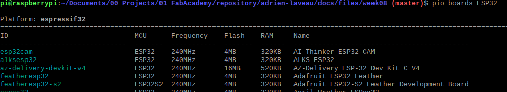
First let’s look for the board containing the ESP32 that looks like my board.
pio boards ESP32
Pio outputs a list of board, the first one esp32cam looks fine. I will test with it as it fits the specs of my board.
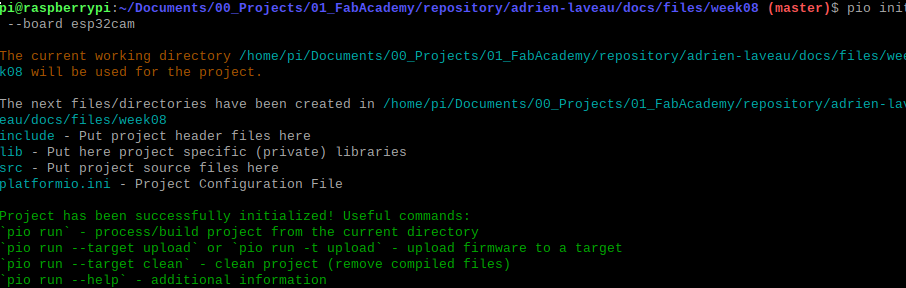
I initialize a project in the directory of my choice with the esp32cam.
pio init –board esp32cam
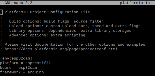
Once this is done, let’s have a look at the content of plateformio.ini
In this case I have nothing to add, the basic settings seems to fit my need.
We will see if a simple blink code compile and flash to confirm that.
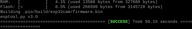
The code for my application has to be located in /MyProject/src/ I will use the exact same code I used in Arduino IDE as the platform mentionned in the platformio.ini is Arduino.
To compile the code, place the terminal in the project directory and run the following command.
pio run
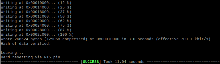
Finally to flash the compiled code run the following command :
pio run -t upload –upload-port /dev/ttyS0
Tip
As I flash using GPIO I use the option –upload-port to precise which port to use for flashing.
And the flash process goes without any issue.