2. Computer Aided design
This week we will put some volume to our ideas !
Assignment
2D
Basic drawing workflow
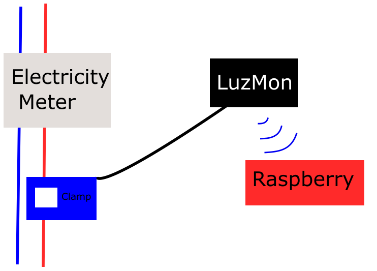
For this assignment I will design the idea of my final project on inkscape.
First I place geometric forms for the different elements of the project. Being a vector software these elements can be reshaped and recolored at anytime and selected as individual parts.
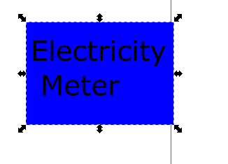
Another advantage of inkscape is that one can work with layer. In this small project I have created 2 layers
- Elements : for the physical parts
- Connection : for the wires and wifi signal
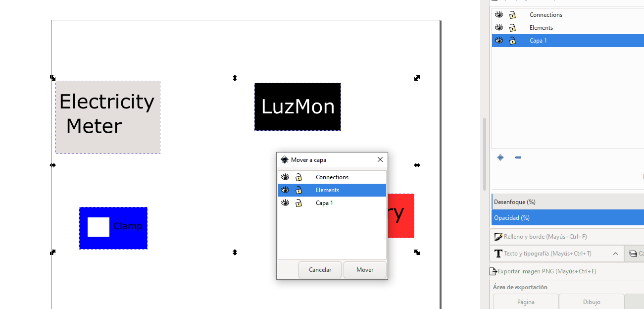
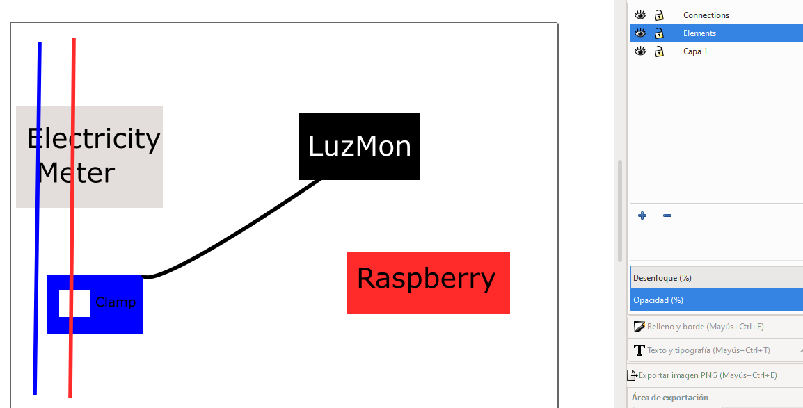
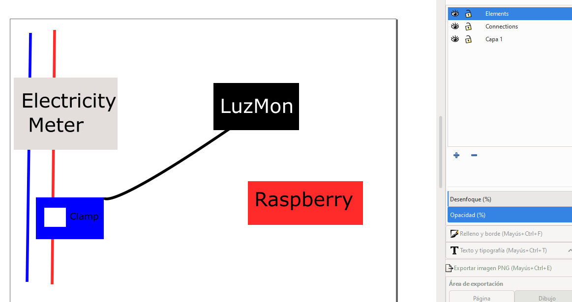
The use of layers can be as follows. On the left picture the order of the layers order is not correct because the wires are seen on the top of the electricity meter. On the right picture I have brought the Element layer on the top and the issue is fixed.
Now it is time to play with curves. To create the wifi signal I did three straight Bezier curves that I can modify afterward using a specific tool that acts on the line curvature or end point orientation.
And here is the final result
Extra info - Masks
For the final project I wanted to cut pictures and have a transparant background.
To do so I had to do the following steps :
- Draw a closed bezier curve following the shape you want to keep (or remove)
- Draw a rectangle bigger than the whol project
- If you want to
- Keep the area :
- shape in white
- rectangle in black
- Remove the area :
- shape in black
- rectangle in white
- Group the shape and the rectangle and place them on the top of the project (having the shape always above the rectangle)
- Right click -> Apply mask
It will keep or remove the part inside the shape depending on the color you gave to the shape. More info here : https://inkscape-manuals.readthedocs.io/en/latest/clipping-and-masking.html.
3D
Blender, FreeCad, Fusion … ??? A lot of softwares were presented this
week. I did not know which one to work with.
Well this video inspired me into testing a little bit of all
- Blender for trying out
- Normal CAD software for the final design
Blender
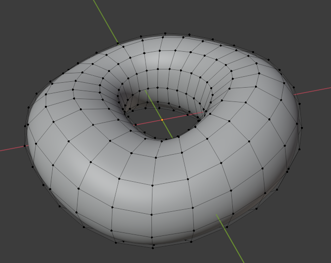
To try Blender I worked on the famous Donbhing which I had not seen in other software. I was working on my mesh
and checking the render without seeing the effects because the transformation
was not applied.
The mesh is crucial because it will be the base of all the effects you will apply.
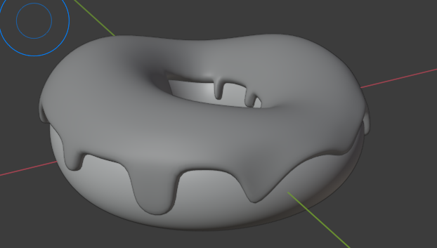
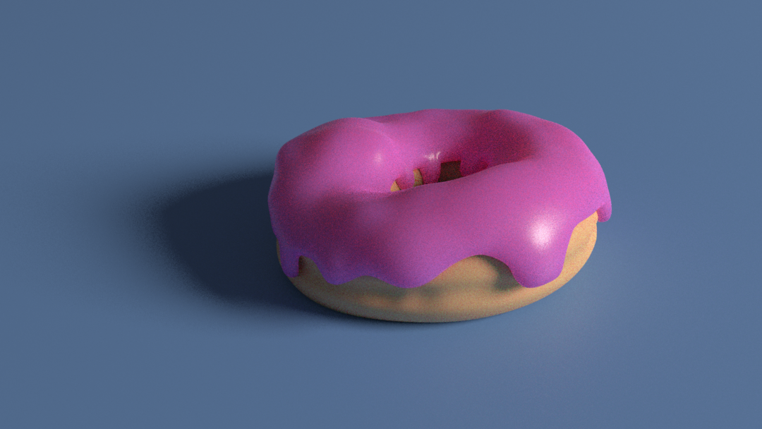
Once the donut is ready, using the upper part of your donut by selecting the corresponding verticies you can create an offset to make the icing. Then using the powerful “sculpting” tools of Blender and choosing the impact of your tool you can make the icing leak on the sides. This effect is not imaginable in a conventional CAD software.
rhino Once the 3D aprt is ready, one can start playing with the light and the various rendering engines.
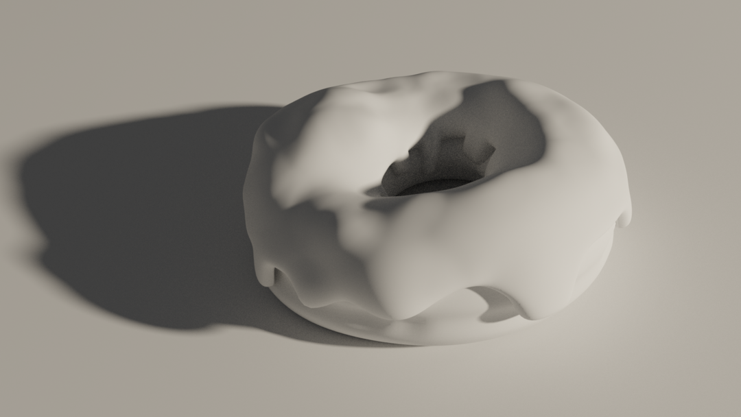
I already really liked the Black&White Donut, but adding the colors makes it truly real.
And I even tried to work with CURA to see a simulation of printing the Donut. I was only able to export the icing at that time.
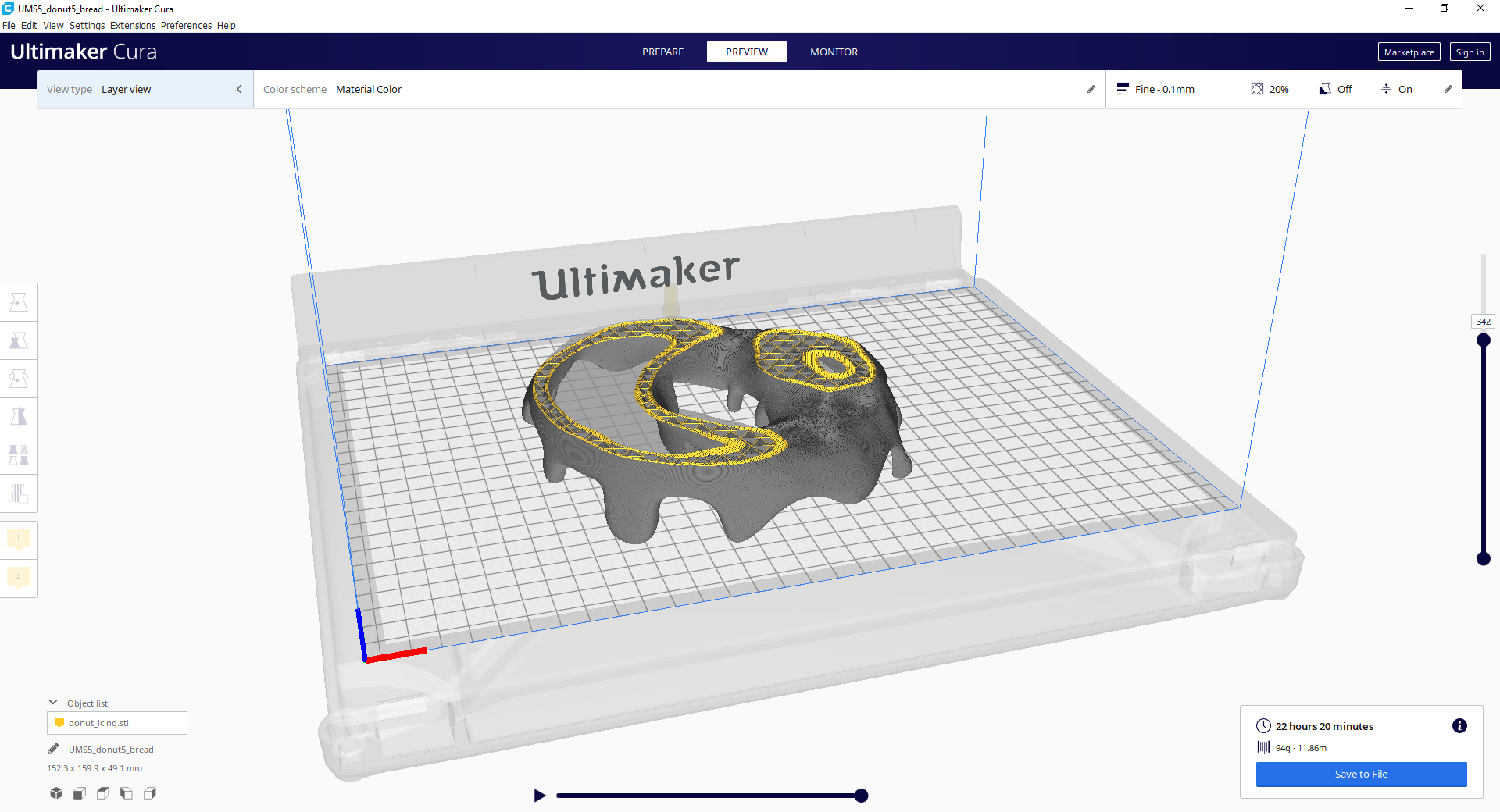
Here is the final result. It is not as nice as the Blender render, but it allows to share the final design in a handy way.
The experience was interseting. But if I missed just one of the steps of the tutorial I was pretty lost. For the time frame I have, the experience is too different from what I am used to.
Useful link for Blender : here
Tip
F3 will show the command search toolbar.
FreeCad
I tested FREECAD spending time on tutorials from ObiJuan.
Step by step ou can learn the basics of FREECAD.
I have spent several hours working on them until I reached an issue for
assembling parts which was a problem for me. There was a graphical bug on
my laptop when using the menu ‘Edit -> Alignment’.
I have been on contact with the community of FREECAD user but without succes.
You can find my posts here : https://forum.freecadweb.org/viewtopic.php?f=3&t=55348
So to have an example of FREECAD I worked on my version of the FABLAB logo.
Freecad : detailed example
In May there was an update of FreeCAD which corrected the bug I had at the beginning of the Fabacademy. I could finally make my final project with this software.
I will not explain with more detail how to create a simple model with the basic functions.
Freecad is based on Workbench that can work independently or in a combine fashion with some common functions. The nice thing is that the open source community share some extra workbenches that can help you in your design. And when a workbebnch is mature enough it is even possible to download it directly from within FreeCAD using Tools -> Addon Manager.
To start creating a part you have then to choose your workbench. I will talk about the two I used most.
- Part : It is not the one I got used to when using SolidWorks during my study. He the user is invited to create volumes and add/substract them. In the video bvelow I show a small example on how it works. I first create a cube then I add a cylinder that I mode a little bit. After that there is the option to align parts (the one which was not working). And the heart of this workbench is the boolean operation I show at the end where you select two solids and add or substract them. In this case I substracted the cylinder from the cube. What I do not really like is that it feels less “engineered” and leads me to show you the second workbench I used.
- PartDesign : This workbench works on what is called a body. A body is a succession of elementary volume addition of sbstraction but based on sketches where it is easy to set up your dimensions. In the video I made you can see that I select the workbench I want to use “PartDesign” and automatically I am invited to create a body. Then the next compulsory step is to create a sketch. You can see how I set up the dimensions. Once the sketch done you validate it and select the kind of elementary transformation to be applied. As there is no initial volume the logical choice is to “pad” the sketch. Starting from this new volume I then make a hole based on a new sketch.
Freecad : extra tools
Two extra tools I used a lot for my design are :
-
Dimension sheet. It allows you to have an excel sheet in which you enter all the dimension that will be useful for you project and the use them when you create your sketch.
-
Exploded Assembly Add-on In one click this addon allows you to create assembly of your design.
I have made a small demo of both functions in the video below.
OPENSCAD
With a combination of python, interface etc you can create 3D file easily
A little bit of everything
To finish the CAD week, as I could not work on assemlby with FREECAD and
in the futur I might have to switch from one software to another I wanted
to do an assembly based on several softwares.
I got “inspired” by this video.
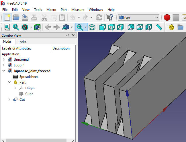
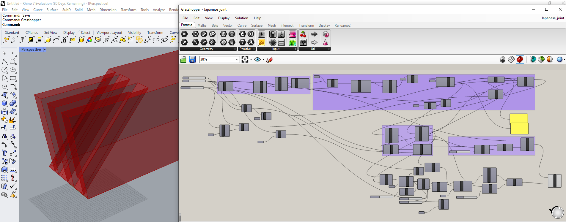
A joint used in the corner of the floor sill discovered while taking apart Japanese 92 year old house.
I created one part on FreeCAD, one part on Rhino with the help of GrassHopper and I did the assembly on Xdesign. See the result below.
The final result was assembled through XDesign which is pretty easy to use. And accept various file origin. But I would recommand to work with IGES because they gave the best results.
When doing the assembly on Xdesign I realized the parts did not fit together because of an error I made in the FREEDCAD design. I was so much focused on the “notch hole” that I had not see the obvious part. But in conclusion I learnt to use several softwares and I will work mostly with Freecad because I like the fact that it is OpenSource and has a responsive community.
Files
- Inkscape : PRoject drawing
- Blender : Donut tutorial
- FreeCAD Logo : Fabacademy Logo
Japanese joint
- Freecad part
- Freecad export for Xdesign
- Rhino-grasshopper
- Rhino export for Xdesign
- Assembly export from Xdesign
- Assembly export from Xdesign for sketchfab
Lecture notes
2D
Raster vs Vector
We learnt the difference between Raster and Vector image file. It
seems vector is a nice format but it will need computing power.
Will it run on the pi ??
Color workspace
Tip
For the web you have to use SRGB
Image format
JPEG, I have just learnt that JPEG format degrades over time, there is a video about it. For my web I will try to use resized PNG.
Tip
Max height for web image = 1080p ! For easy convertion use ImageMigick
convert Input.png -resize 1080 Output.png
3D
NURBS vs MESH
As in 2D you can find raster and vector The 3D world seems to be split into classes.
Mesh <-> Raster
The 3D form is represented by a cloud of point linked by straight lines. It requires memory but less computational power
Tip
Mesh files can be saved in :
* STL : does not save color information, neither relation between points
* OBG : saves form, units and color
Nurbs <-> Vector
As for Vector images, it uses less points. And to describe the shape between two points we use mathematical equations. This require computational power but files a smaller and there is no scaling issue.
Assessment
Learning outcomes
Evaluate and select 2D and 3D software
Demonstrate and describe processes used in modelling with 2D and 3D software
Have you
Modelled experimental objects/part of a possible project in 2D and 3D software
Shown how you did it with words/images/screenshots
Included your original design files
assignment model (raster, vector, 2D, 3D, render, animate, simulate, …) a possible final project, compress your images and videos, and post it on your class page