3. Computer Controlled cutting
Experimenting
Group assignment - First investigation

The group assignment was the occasion for us to start sharing work and start investigation of the tools we had just learnt to use. In this case the Trotec. 3 samples plates were done on :
- Plywood
- Acrylic
- MDF
The conclusion I can take from the tests that were done are the fllowing ones :
Plywood
For rastering (called engraving on Trotec), at high power the difference between power scale is rapidly
lost, so it might be interesting to avoid too high power to avoid the risk
of burning you material as you will not gain in contrast. (and you save energy  )
)
When it comes to flex-cuts it is important to cut the wood in the direction
on the grain otherwise you loose flexibility and it breaks easier (we tested…)
One test we have not done but that would be worth it is checking the impact
of the speed/power ratio for cutting to avoid too high carbonization on the side
of your material. Indeed once cut and burnt the wood leavs stains on the parts
that might not be desirable from an esthtic point of view.
On our 4.2mm plywood the kerf was important (almost 0.6mm) and has to be
taken into account for the design.
Acrylic
The rastering of the acrylic has the same drawback as the plywood, the contrast
is not really good and rapidly saturate the machine. To improve the results
a discretization of the 50 to 70% of power might of interest.
The flex-cut pattern that we used did not have constraint release point and
are pretty brittle. We loose on flexibility compared to the plywood and
for good flexibility one might want to look for specific “flex acrylic patterns”.
In the case of this material we had no issue with burning the sides, we only
loose a little bit in transparancy but that might be an effect one would like
to play with. On the Multicam machine during the first lecture, the small parts
we cut were pretty much transparent. As a beginner it is hard to compare the
cutting parameters but that might be due to those more that due to the machine
the technology being the same.
MDF The MDF is the one who seemed to provide the best rastering contrast scale when ranging the power from 0 to 100%. So if one is looking for wood rastering he might want to go for MDF. The kerf is also smaller than for plywood possibly due to the material hardness compared to plywood. For the flexcut the MDF seems not to be isotropic (on its main plane at least) which allows to think that the cuts can be done in any direction and will have the same properties (proper testing would be required to confirm this theory).
Assignment
Preparation of the hardware
Before starting the cutting work let’s not forget the golden rules.
- Is the ventilation on ?
- Have we done the focus ?
- Is my material allowed on this machine
- Stay next to the machine be sure to know how to stop it.
Then there are more general rules for the quality of your work.
- Be sure to know your material to have to good parameters
- Is your material flat ? If not put the corners upwards and clamp them with paper tape.
- Is the material correctly placed in the machine ?
And now to save time, with the Trotec we have seen that the orientation of the part, or the order in which you run the steps might influence a lot in the running time. Also it is important if you can to send only the “job” and not all the cutting area to the machine, otherwise the machine has to scan all its cutting area and it takes more time.
Preparation of your files
Let’s take one step back. Before going to the actual machine one should be sure that the files he prints are the correct one, or you might end up with something smaller or bigger than expected.

Once you are sure that you send the part you are looking for, do not forget
to check and “think” you design. Indeed after having spent the whole morning
on my parts and then cutting them, I realized that they cannot be mounted  .
.

The proper design
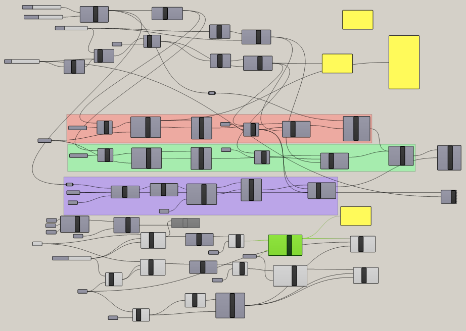
We learnt how to create parametric design in Rhino/GrassHopper. The workflow is pretty new to me. The tricky part is to know which functions actually exist and their role. Once you are getting used to it the design is made easier.
My idea is to create a single part that can be assembled as a box of any size, and also that part can be added on the size of the box to make different kind of structures. The assembly uses press-fit.
Main challenges
- Can it be mounted ?
- The kerf impact on the joint
The first test was used for testing the machine and was not so successful. I gave a second though to the design to confirm it can be properly mounted.
First experience
Laser cutting on the Trotec 100 : interior notches
Laser cutting on the Trotec 100 : Cutting the part
The design
I will design the following press-fit kit to make boxes and towers. It can be assembled in various way to produce various type of constructions.
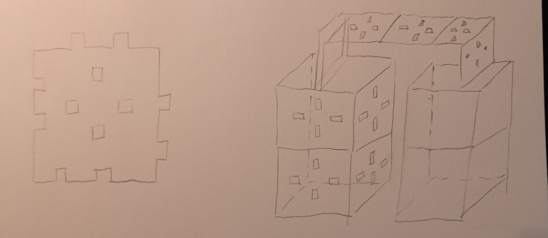
One can find 3 sets of notches :
- Male notches
- Female notches
- Internal notches
Male and females notches are here to make regular box, the internal notches are here to give another dimension to the game. While created it I still do not exactly know how I will use them but the game will reveal itself while playing.
I sketched the design on Rhino first but it was a lot of work and I was not able to easily come to a nice way of doing it. It got pretty messy pretty fast.
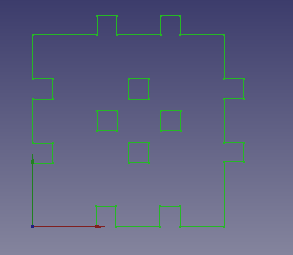
So I switched to Freecad to make the sketch. It was easier than rhino/grasshopper in my opinion. But an important point if you are choosing your cad software is that it seems Freecad is a bit limited on the constraints choices. You can do everything but you always have to find workaround. Below is my sketch, I am sure it can be done in numerous otherways but this is what I came with.

This model is parametric based on the spreadsheet module of FreeCAD. Below you can see the simple spreadsheet I created for this design. I really like the easyness of using the module and how you can present you parameters.

Creating formula
The only drawback is that creating formulas based on the parameters can get complicated. I recommand to make all the formulas in the spreadsheet and not in the parameter box.
- It is much easier to check
- Better for communication
The base form is like this
The final part

Vinyl cutting
From the video of the lecture I learnt that to process a file you have to :
- Properly install your vinyl placing the rollers on the white marks and blocking the vinyl with the backside lever.


-
Choose the blade deepness so that it cut through the vynil but not the lower layer.

-
Set the force (around 120gf to start) and speed (around 12-18cm/s)


Remember : smaller = slower
The settings are starting point and should be adjusted after proper testing. Do not hesitate to use the test function. (Really easy to do, just push the “test” button for 2s)

Once the settings are ready we can start preapring the file to cut. I chose the following simple cat desgin to be cut on a black vinyl. I found the file on Pinterest (https://www.pinterest.es/pin/522487994263618529/). The file had to be adapted a little bit to remove the watermark.

The software that allows us to work on the vinyl cutter is smartly called “Cut Studio”.

After import the file into CutStudio we have to tell it the size of our working area. The easiest way is to get it from, the machine as shown in the image below.

The comes the moment to place the design correclty on the working area. Cut studio offers various options such as rescaling, orientation etc …
Danger
Remember to check that the cut test is not in the working area. Place it “below the needle” by moving the vinyl toward yourself.

I am now ready to cut !
Here are the two designs I cut


Now my cats know where to eat !

I really liked using vinyl cutting because it is a quick and high quality mean of creating visual support. It has different outputs in terms of color and material (one of the classmate cutted copper to make a pcb !)
Files
Videos
Blowing on the Pi while encoding video to cool it down …
Lecture notes
Below one can find my lecture notes as I wrote them during the class with some tips and recommandations.
MultiCam
Before starting
- Start the chiller (laser has to be watercooled)
- Start Air extraction (in BCN, common for the three laser cutter)
- Start Air Compressor for machine movements
- Start the laser cutter
Using the machine
Long axis = X - Short axis = Y
- Do the reference so that it knows its position
- Change moving speed with “JOB”
- Press 0 to set (keep pressed)
Tools references
- 1 = Cutting (ref = 0,0)
- 2 = Engrave (ref = 0,0)
- 16 = Raster (ref = center)
The remote control is made in such a way that the commands to create a part a set up in columns to help the user follow a precise workflow (for basic task at least).

The user can create simplified job to test the machine. Like cutting squares or circles. During those tests we could see the progressive adaptation of parameters to reach the desired goal. In the picture below we can see two effects :
- The laser does not go through the part
- The piercing effect, in the corners the laser go deeper
In some case, one might want to fine tune the laser to avoid uncontrolled piercing effect. Indeed, when the laser reach a corner the linear speed changes due to machine limitation and stays longer a on point which provok deeper holes.

First shot with the multicam.
Creating a file
For this machine, the files have to be sent through the network using Enroute4
The workflow is the following
Rhino -> dxf -> Enroute4
- Create file in Rhino
- Export as dxf
- Import in Enroute4 (CAM Software)
In Enroute4 :
- New file -> multitool
- Merge selection (to have 1 line instead of several)
- Choose colors corresponding to the tasks
- Export to the multicam
On the machine click the connection Button (1st column, 4th row) to see the list of files. The following example has a contrast issue and would have to be reworked on a software like Inkscape.

Trotec 100 & 400
The Trotec laser cutting machine are smaller, almost “office hardware”. You deal with them like a printer.
Do not get to comfy. They are dangerous
The basic idea is to send a file made of of colored lines and surface to them assign a set of parameters to each of those. In this machine the bed is mounted on rails and go up and down to allow the user to adjust the focus. To do so we use a plastic gauge mounted on the lense. When the plastic gauge fall down you are good to go.

Clean the lense
The main danger for the lense is the dust that get stuck on it because when the laser is on, the dust gets hot or burn and damage the lense. A proper maintenance is important.
Assignment
Group assignment:
  characterize your lasercutter's focus, power, speed, rate,
     kerf, joint clearance and types
Individual assignment:
  cut something on the vinylcutter
  design, lasercut, and document a parametric construction kit,
     accounting for the lasercutter kerf,
     which can be assembled in multiple ways,
     and for extra credit include elements that aren't flat
Learning outcomes
- Demonstrate and describe parametric 2D modelling processes
- Identify and explain processes involved in using the laser cutter.
- Develop, evaluate and construct the parametric construction kit
- Identify and explain processes involved in using the vinyl cutter.
Have you
- Linked to the group assignment page
- Explained how you parametrically designed your files
- Documented how you made your press-fit kit
- Documented how you made your vinyl cutting
- Included your original design files
- Included your hero shots