1. Final Project First Steps
Before starting the final project, I would like to share with you :
- The reason for my final project
- What I have in mind for it
The origin
In 2018 I had all the electric installation of my flat made new to follow
the norms. I used the opportunity to have a different fuse and electric
line for each appliance to make it handier.
Now the first bills started to come in and I had the curiosity of knowing
which of my appliances consumes most. The flat being 100% electric
 it makes sense to know where i should take care to keep my bill
reasonable and keep the planet green
it makes sense to know where i should take care to keep my bill
reasonable and keep the planet green  .
.
The plan
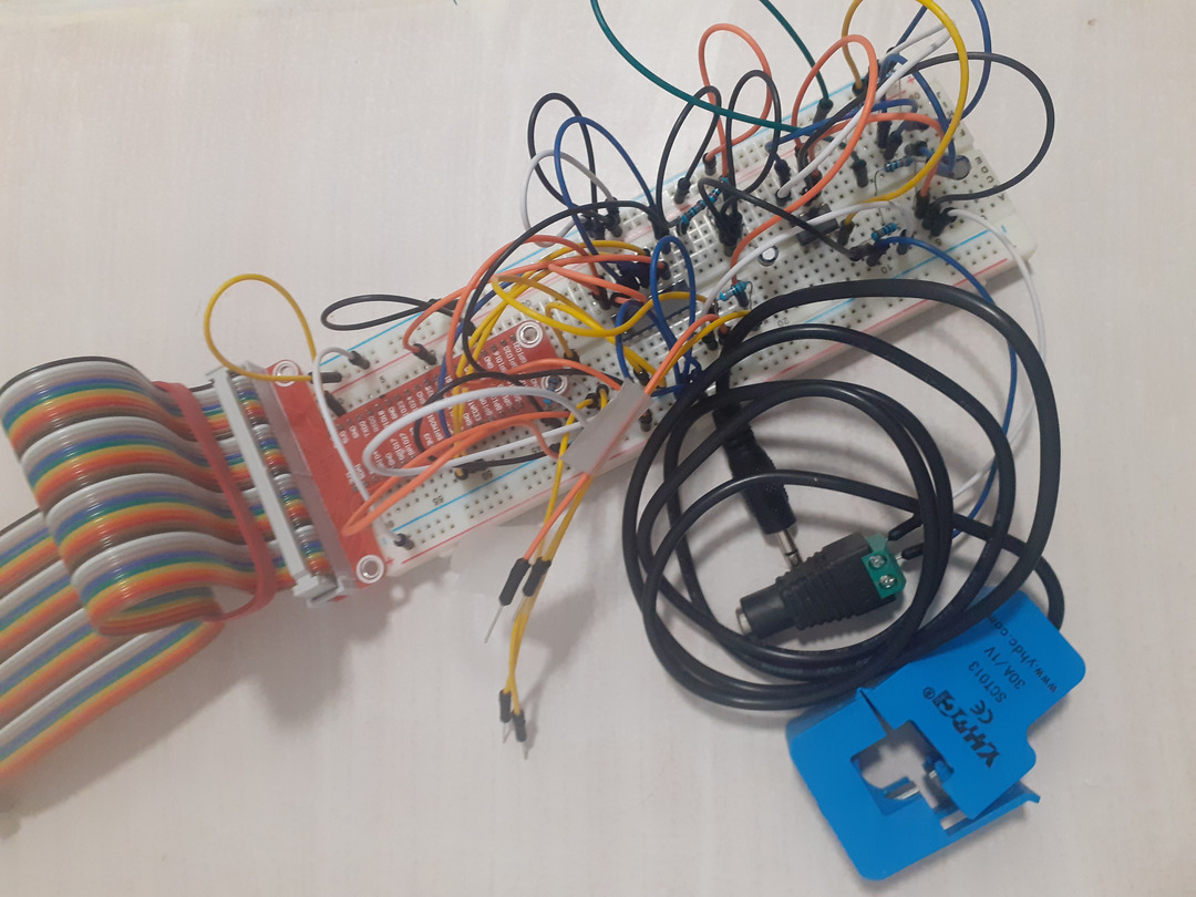
Based on the great documentation available at OpenEnergyMonitor I created a first sensor based on an ampermetric clamp and my raspberry pi as you can see below :
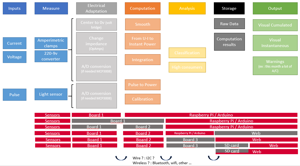
This small animation will show you what I have in mind :
Now I would like to do the following :
- Have 1 clamp per fuse
- Gather all the signals to a Signal Management board (maybe each clamp could have a small board to send the data to the data logger without cable)
- To filter signal
- To Transform the signal into meaning full values
- The data has to be then sent to a DataLogger : cables or wireless ??
- Another chip would need then to make computation based on this data to give me insight on my electrical consumption behavior.
Converting this into a task list would give :
- Get to know the sensor
- Mount it on a board
- Measure something
- Visualize the data
- Have some meaningful data
(Let’s be honest, I made the list to try the Mkdocs feature for tasklist…)
Note
If after using the device for some time, I can detect that the water-heater
consumes more and more because of limescale deposite on the electrode my goal
would be more than reached  !
!
Functions to develop
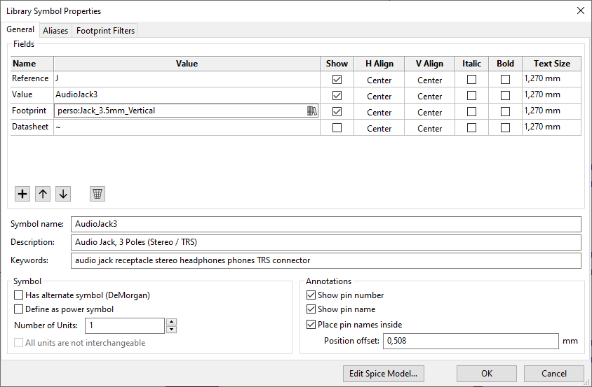
Creating foot prints
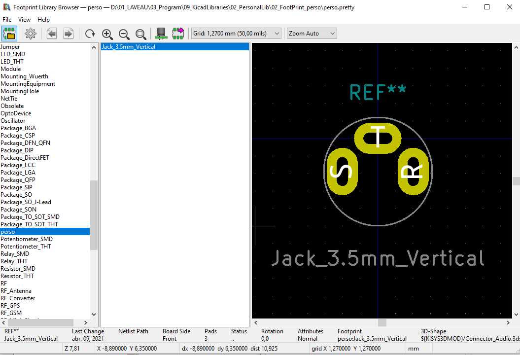
My project is using specific 3.5mm vertical jack connectors that are not available in Fabacademy library neither in Kicad. So I created my own component based on :
- FabLab symbols : Connector - AudioJack3
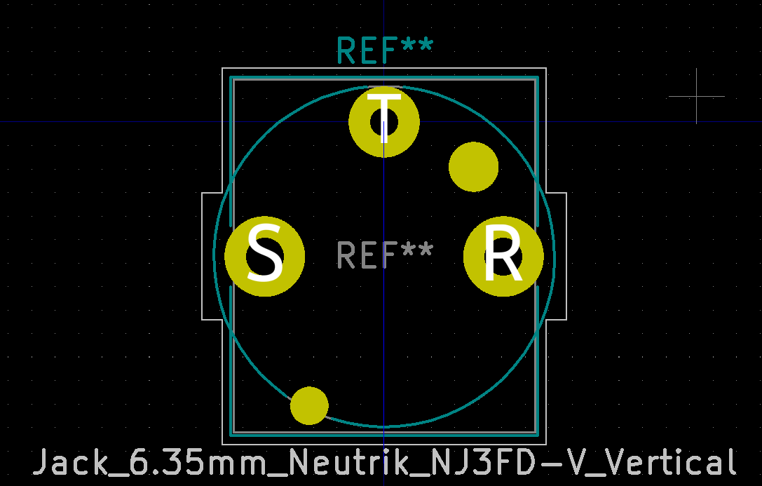
- Kicad footprint : Connector-Audio Jack_6.35mm_Neutrik_NJ3FD-V_Vertical
The Symbols stays the same but I added the modified footprint from my library. I adapted the pads sizes and part courtyard to fit my own part.
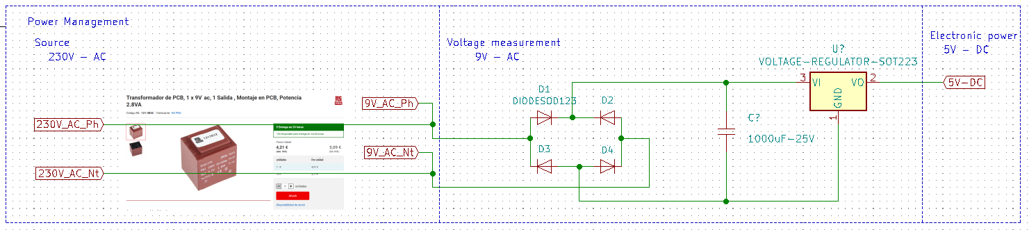
First proposal of power management :
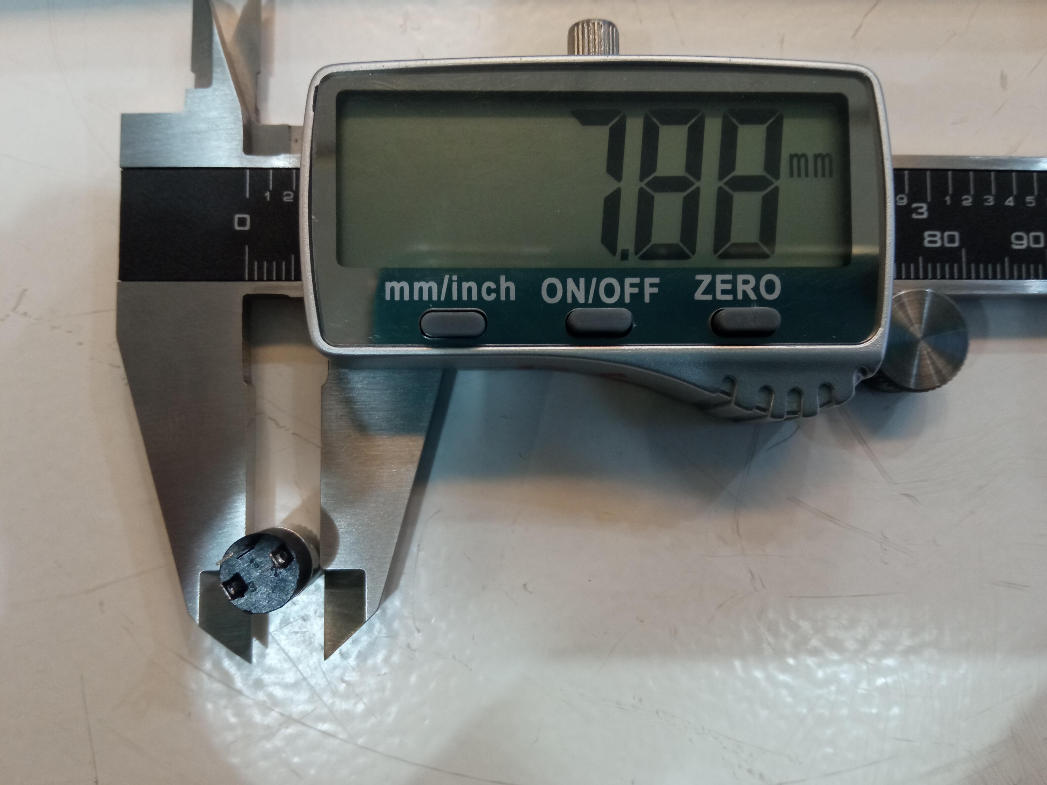
Casing
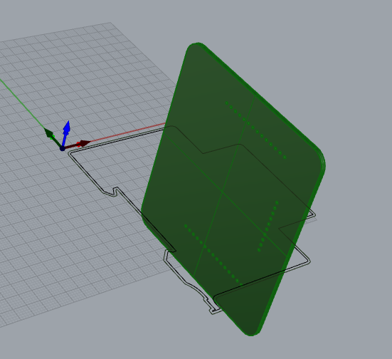
use this link for the pins https://www.thingiverse.com/thing:4796603
Installation
Here is how I install the finished product in my fuse box.
Let’s make it Global
If I do the job well, this web should help anyone having access to a FabLab to reproduce (and improve the system) so that one can be sensibilized to its elecetricity consumption at home and better understand its own habits.