16. Applications and Implications
By answering a few questions below I will share the reflexion and preparation on the project.
But before that, this page explains a bit the history of the project
Some questions on the project
What does it do ?
To answer this question there is a method which called Functional Design which uses two tools called :
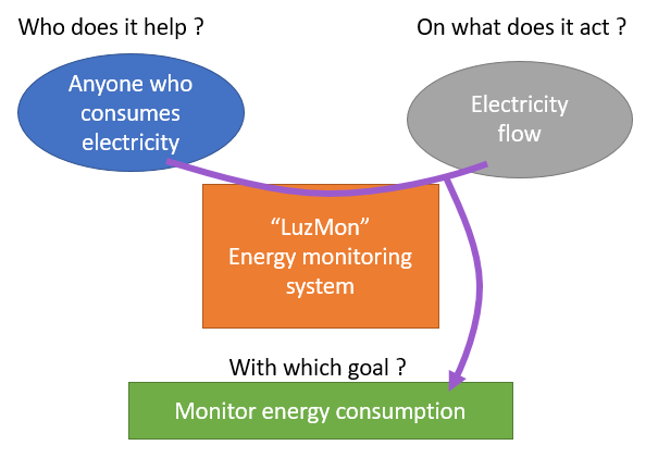
- La bête à corne (The cow)
This tool is used to put in word the objective of the product. It consists in answering 3 simple questions but of outmost importance because they will shape the design direction of the product.

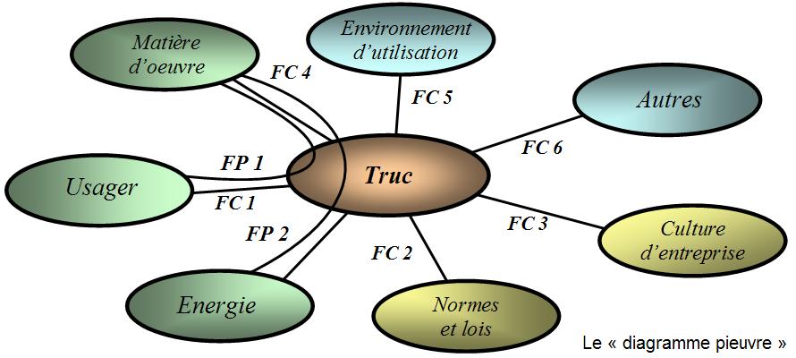
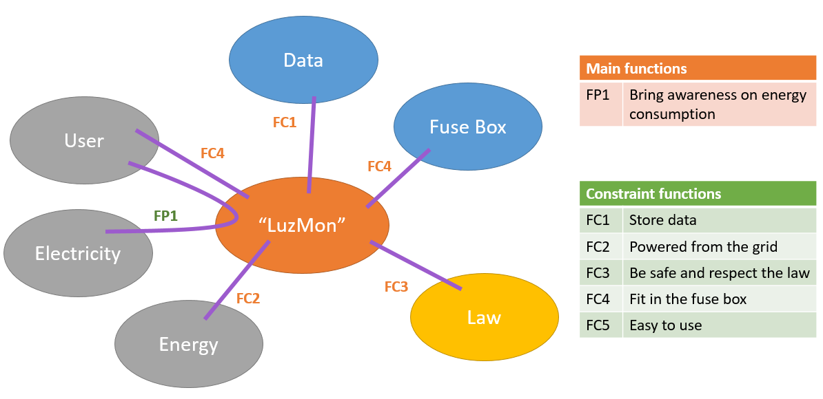
- La pieuvre (The octopus)
Once the goal of the product has been defined, one has to see how it will interact with its surrounding by finding the Functions on the products : * Main functions : the functions that will make the product reach its goal * Constraints functions : the functions that the product has to respect due to its surrounding
Now if I applying those tools to my final project here is what I get
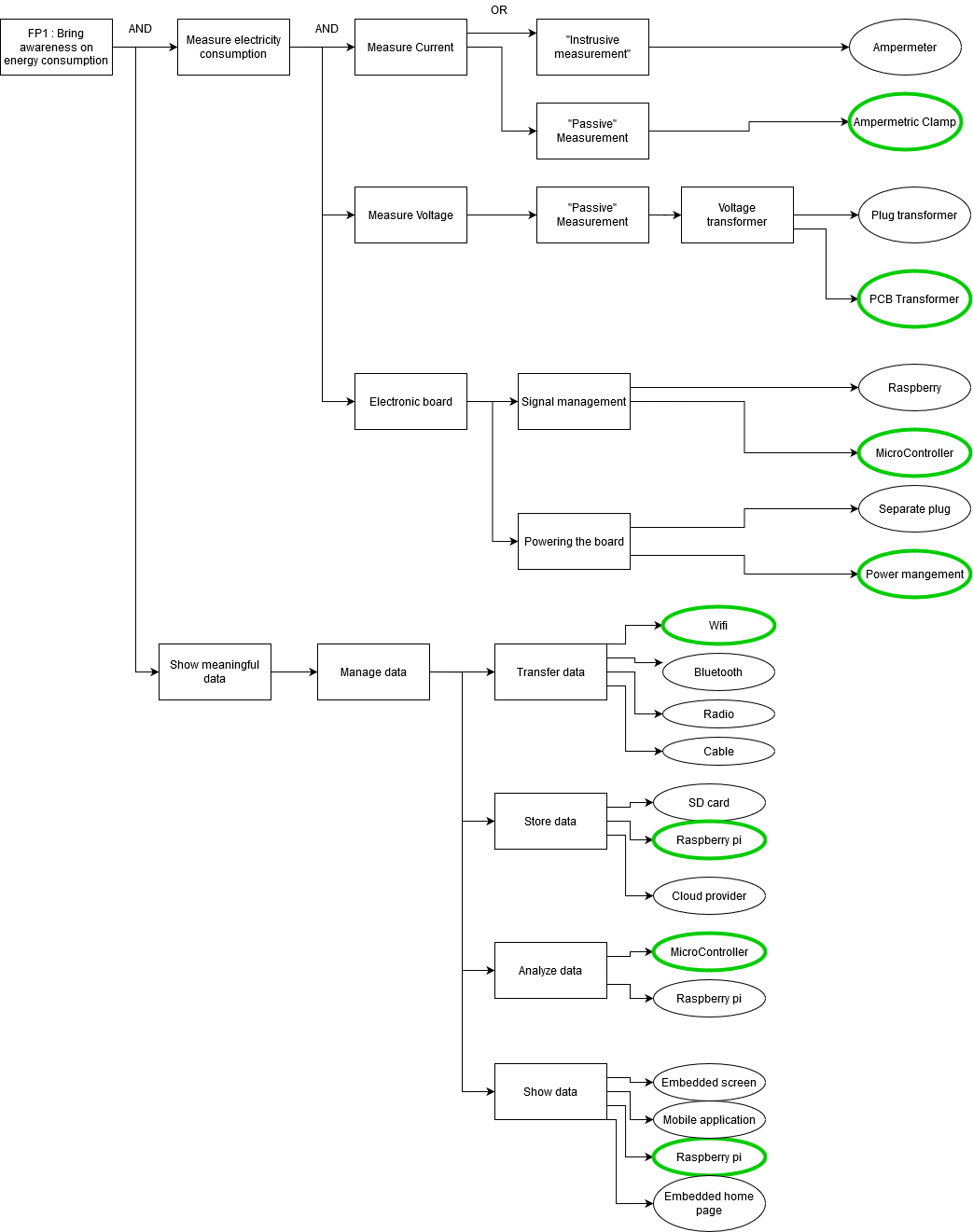
Once all these functions has been defined there is a last tool called “FAST” (function analysis system technic) to match technical solution to the functions. This diagram is described in the norm NF EN 12973.
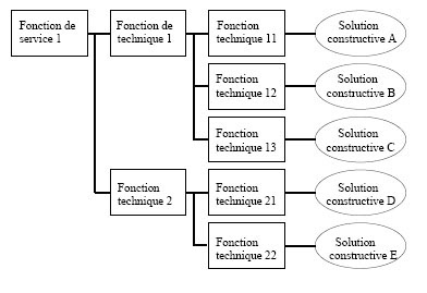
The SAFT diagram applied to my project is the following one
Who’s done what beforehand?
  I have done a bit of reasearch on previous Fabacedemy projects as shown here.[](../../assignment/week01/#biblography)
  But the most important piece of work comes from the [OpenEnergyMonitor project](https://openenergymonitor.org/)
  which gives a lot of insights on how to create such a system and also provide two libraries
  to manage signal and data.
  This repo is about using part of the library of OpenEnergyMonitor with ESP32[EmonLib-esp32](https://github.com/Savjee/EmonLib-esp32).
What did you design?
I have designed * The Electronic board for the microcontroller * The shield to route the signals and do some analogic work * A light pusle sensor and its casing * The electronic casing * Some Modular current sensor boards
Materials
Here is the complete Bill Of Material of the project. Using the file filters one can see that I have split the the components between the boards. This is especially interesting for the JackBoard (current sensors) depending on the need of the user.
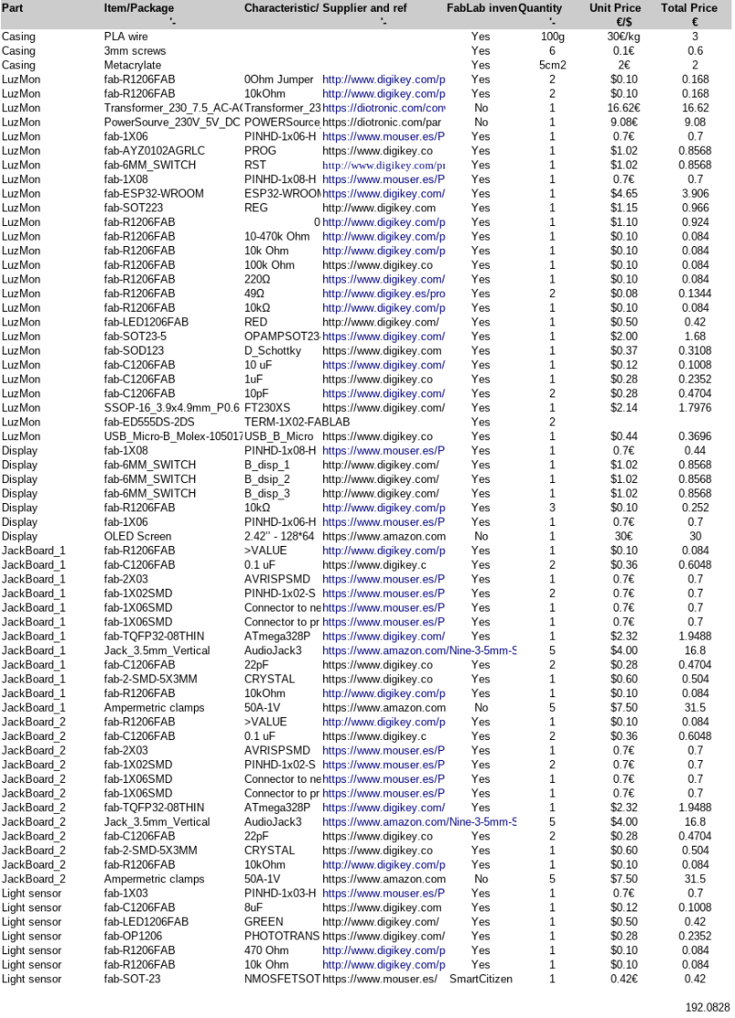
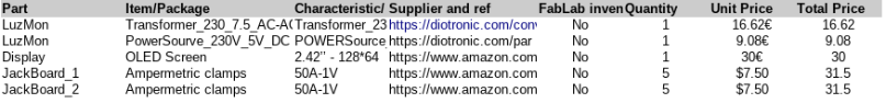
In the list one can see the origine of all the components and that some of them (the most expensive ones) are not part of the inventory because they are a bit specific.
Here is the complete BOM in OpenOffice format.
What parts and systems were made?
I have designed and created the electronic and the casing for the electronic.
Also the clips are fullly 3D printing and were created with pins to avoid screws.
What processes were used?
- PCB milling
- 3D printing
- Laser cutting
- Embedded programming
What questions were answered?
Here is a list of question I had to solve to go on with my project.
Electronic
I had a reflexion concerning the Layout of the electronic that one can see reflected in the following table.
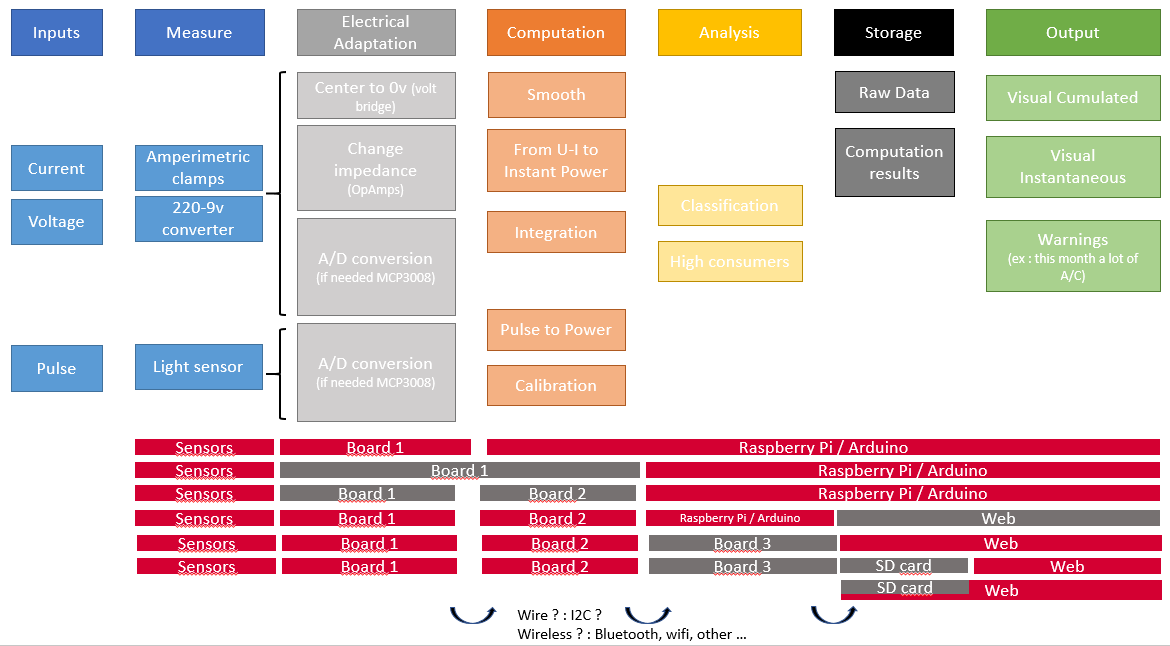
After a lot of thinking, research and discussion the following layout was chosen :
- LuzMon : The main board receiving the ESP32 and the PowerElectronic
- JackBoard : the board receiving the current sensor jacks and the ATmega for signal analysis. There is two of them to make it modular.
- LuzDisplay : the board that make the bridge between LuzMon and the OLED screen. It also contains 3 push buttons to control the screen
After that I had to solve the following questions ( for which I have some answers) :
- Is it reasonable to have 3 microcontroler in my project ? –> Yes
- Communication I2C (ESP32/ATMega1/ATmega2) –> It is fine
- Powering ? Flash, serial, 230V –> Can be done
- Flash ? how to manage two SPI ports on the same board –> I must have one per Atmega
- Can I remove the FTDI ? –> Yes
- Can I share crystal between ATmega –> No
Data management
I wondered how to show and store the data. I decided to go for the raspberryPi because I prepared the whole workflow during the Networking week and I found it a nice way to do. I will use Node-red for the interface and InfluxDB for the database.
I also decided lately to add a screen to be able to give feedback for the user when he opens the fuse box or if he does not have a raspberry pi.
Casing
I have been thinking of the best way to produce the casing. The choise was between 3D printing and Modling&Casting. I finally chose 3D printing thanks to its effectiveness and possiblity to update the design quickly.
What worked? What didn’t?
I had several issue with the ATMEGA.
-
Flashing: because I used the raspberryPi as an SPI module and AVRDUDE direclty without arduino. The main issue is that I was missing the “-b 1000” flag in the flash command.
-
Measuring current data : I used the wrong fuse when flashing the ATMEGA and I was not dividing the clock speed which made all the behavior of EmonLibCM (the library) totally erratic.
Electronic fiability
- Some sensors were not measuring properly because the jack barrel “moved” the copper trace while inserting the current sensor. I would have to think of a better design that does not stress the traces.
How was it evaluated?
My main goal for the fabacademy is to measure the energy consumption of different fuses and give feedback via data visualization on the NODE-red interface.
On a long term I have more objectives as follows (the non compulsory ones)
| Tasks | Compulsory ? | Evaluation |
|---|---|---|
| Design&Produce a casing for the electronic | Yes | It should hold nicely the electronic and fit in the fuse box |
| Produce the electronic | Yes | Having the board to run EmonLibCM and produce useful results |
| Learn how to use EmonLibCM | Yes | Should be able to get the desired info from the sensors |
| Create the Software for data transfer | Yes | Run the EmonLib CM and transfer the data |
| Create the software for the OLED screen display | No | Data should be shown in the screen |
| Create the interface on the raspberry Pi | Yes | The interface should bring insight on the data |
| Manage the database on the raspberry Pi | Yes | Data should be stored a retrievable |
| Sensor calibration | Not for fabacademy, yes for me | Long time measurement should fit the data of the company energy monitor |
| Test the device on a long period of time (>1month) for interface improvement | No |
Content
Below is the check list to be sure that my project fits with the requirements of the final project target.
- 2D desgin Design of the button for the OLED screen
- 3D design Light sensor casing
- Additive fabrication process Light sensor casing 3D printed
- Substractive fabrication process Laser cutting of the protective screen for the buttons.
- Electronic Design All the electronic Boards
- Electronic production Board milling
- Embedded microcontroller ESP 32 and ATMEGAS
- Programming Software control
- Interfacing Node-red-dashboard
- System integration and packaging Caseing and clips to install in the fusebox