3. Software & Interface
Now that my PCBs are ready I have to prepare the code and flash them. I have to develop the following pieces of code :
- JackBoard - ATMEGA328p:
- Adapt the example of the EmonLibCM library to my case
- Replace radio communication by I2C communication
- LuzMon - ESP32 :
- I2C master to fetch data from JackBoards
- Prepare data for MQTT
- MQTT server to send data to raspberrypi
- Wifi Communication to send MQTT data
- OLED screen interaction
- RaspberryPi - Interface
- Create a node-red flow to manage the data
JackBoard - ATMEGA328p
Board description is here.
Flashing the ATMEGA328p with RaspberryPi
As I want to keep up with my Raspberry mood I have to find a way to flash the ATMEGA328p using the SPI pins and my Raspberry. And this way I do not have to use the costly cables available on the market.
Binaries
Before thinking about the cable, we have to know what to flash. Indeed as I will not use a regular cable, ArduinoIDE will not help me for the flashing process. So once the code is ready, the user has to export the binaries and this is the file created during this operation that will be flashed.
To create the binary once your code is ready (and the correct board is selected) : Sketch -> Export Compiled Binary
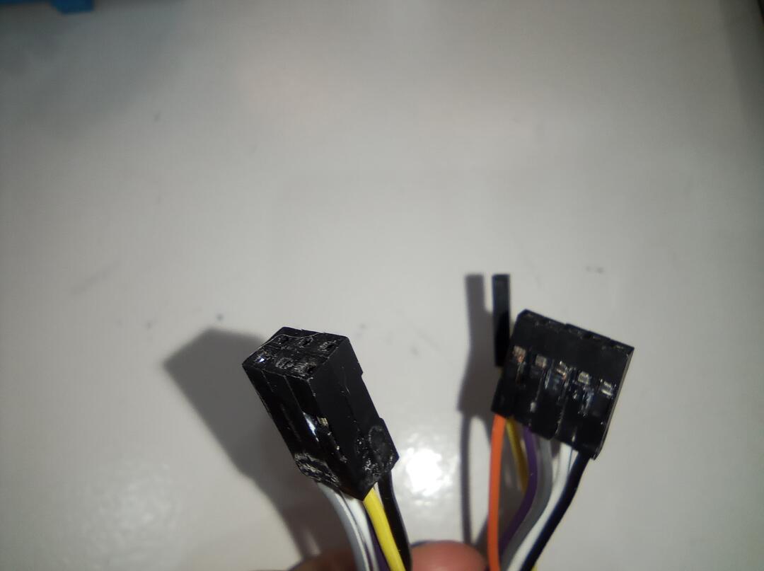
Cable
So first I have to find how to connect the JackBoard to my RaspberryPi.
Warning
To make things “funnier”, but really to save space and complexity, I have no FTDI connector on the board so to check the serial ports I have to place manually some cable on the RX pin of the ATMEGA to see what happens.
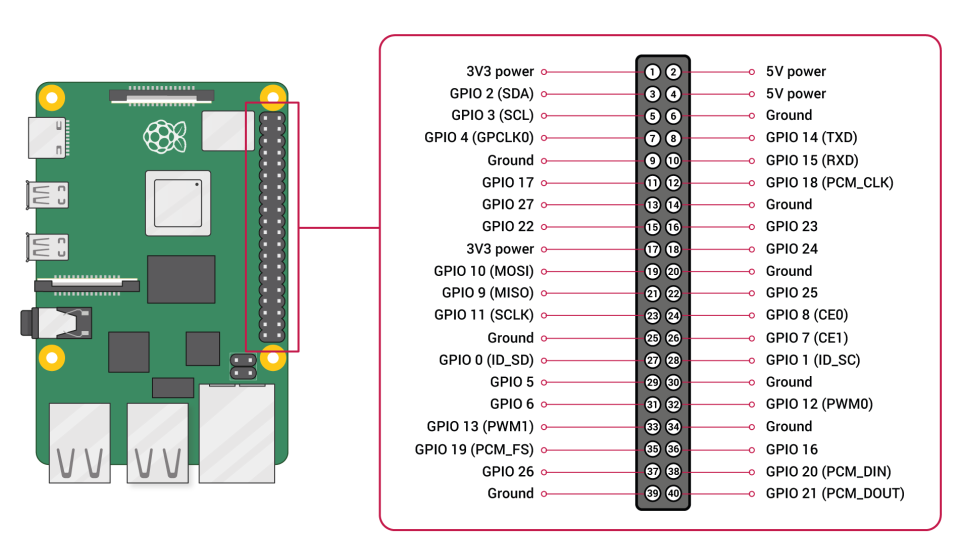
To do so, I created a small cable that links the Raspberry GPIOs and the SPI port of the ATMEGA328p. To create the cable I used the RaspberryPi pinout Out.
Once I was happy with the cable I SuperGlued the connectors together to make it easier to use.
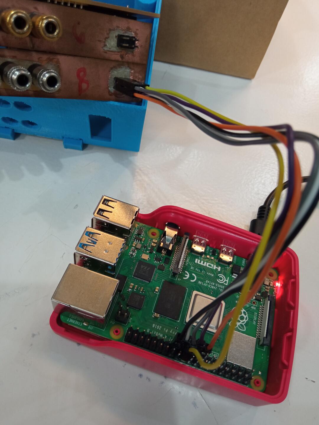
Flashing
Warning
When flashing the VCC and TX/RX have to come from the same source
To flash I followed the steps indicated in this Instructable
First, one has to install avrdude
sudo apt-get install avrdude
Then we have to choose the e-fuse. It can be done thanks to the following web https://www.engbedded.com/fusecalc/
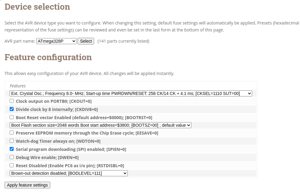
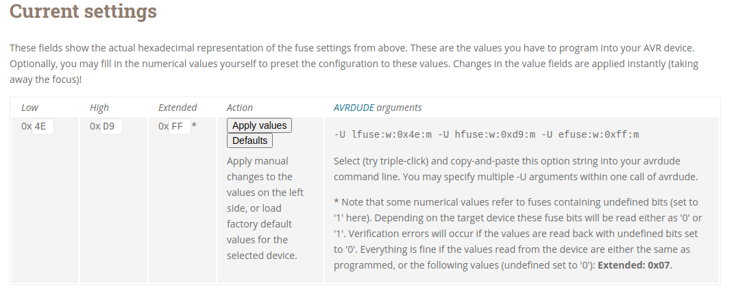
The we can proceed to the flash following those steps :
- Check the connection : sudo avrdude -p m328p -P /dev/spidev0.0 -c linuxspi -b 10000
- Fuse flash : sudo avrdude -c linuxspi -b 10000 -P /dev/spidev0.0 -p atmega328p -U lfuse:w:0x4e:m -U hfuse:w:0xd9:m -U efuse:w:0xff:m
- Code flash : sudo avrdude -p m328p -P /dev/spidev0.0 -c linuxspi -b 10000 -e -U flash:w:EmonTxV34CM_LuzMon.ino.with_bootloader.eightanaloginputs.hex
Let’s decode those commands because they are important :
- -p : it is the part tag, here we flash the m328p chip. One can check the available chip using ‘sudo ardude -c linuxspi -p ?type’
- -P : it is the port where you SPI connector is plugged
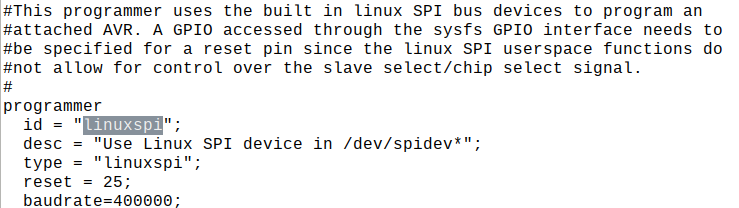
- -c : Here is the magic compared to ArduinoIDE. It uses the RaspberryPi SPI capacities. Its characteristics are described in the file ‘/etc/avrdude.conf’. This is here
that one can find that the GPIO 25 is used as reset pin (to create the cable).
LinuxSPI avrdude - -b : SPI baudrate –> Mandatory (see below the Bug note)
- -e : chip erase before flashing
- -U : action to be done, where to flash and what to flash
SPI Baudrate
It took me a few days to make the above lines working ! Indeed in the example given in the instructable nothing was said about the -b tag. By chance I saw one instruction in a web that was using it and thought “Let’s try” and it worked. Conclusion, to flash using SPI, the baud rate has to be indicated to avrdude.
After all these interesting trouble I finally had my first connection
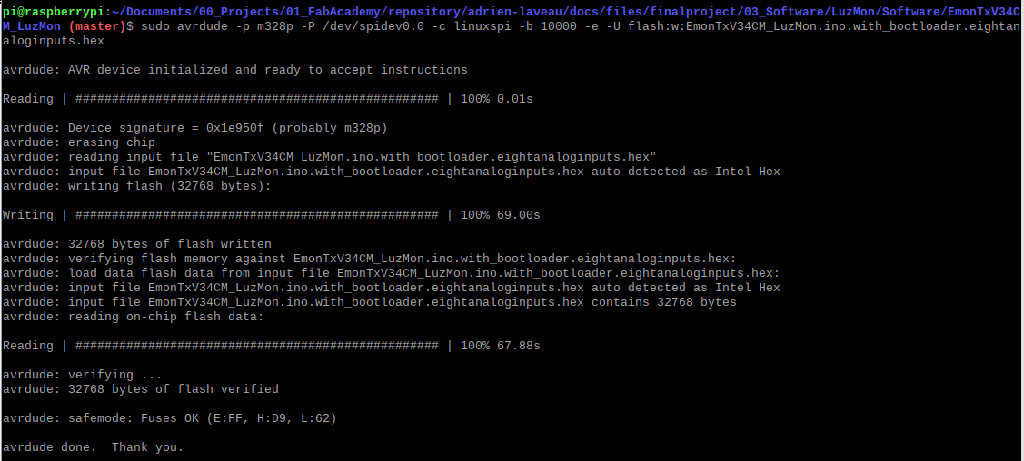
The first thing I flashed was just the example to confirm the flashing workflow.
The Code
During the input week I tried to read current data by myself but I encountered several issues :
- Proper offet removal
- Sensor accuracy
- Proper imlementation of the computation for real/apparent power etc …
When looking in detail at the EmonLib libary I realized the amount of work done here and that it would be a shame not to use it. In the following section I give a bit more details about what has been done by the OpenEnergyMonitor project.
EmonLibCM library
The OpenEnergyMonitor project has developped two set of libraries for energy monitoring.
-
EmonLib This library makes voltage/current measurment each 5 or 10s during 200ms
-
EmonLibCM This library measure continuously the voltage/current of the network to report it to the user.
As I have interest in have a precise measurement and especially concerning current peaks, the EmonLibCM seemed to be more adapted to my needs.
The EmonLibCM is entirely described in this document : emonLibCMUserDoc.pdf
To comment only a few features, the EmonLIbCM can : * Read up to 5 current sensor * Provide calibration methode for the data * Compute Apparent Power, Real power, Current, Voltage Cumulated Energy Consumption, line frequency * Manage temperature sensors * Manage light pulse sensor
A lot of work is done to get clean measurement but at the moment I have not had time to check all the computations in detail. But one example I checked (the one that motivated me to use the library) is explained in detail here : https://learn.openenergymonitor.org/electricity-monitoring/ctac/digital-filters-for-offset-removal
Indeed when I started to work on the offset removal I was doing a simple substraction of the computed offset (half of the ADC range), and when I saw their iterative method I understood the amount of work would be insane if I wanted to make the same.
The Library EmonLibCM comes with 2 examples :
- EmonTxV34CM_min : this example assumes all default values, no calibration needed of the sensors, 4 sensors used
- EmonTxV34CM_max : this example implements all the possible functions to be used to adapt the library behavior
Adapting the MAX example
I started with the max example to have a better understanding of the library.
The main modifications brought are presented in the tab below. These littles modifications took me A LOT of time between flashing issue and hardware/software debugging but it was an extremely interesting experience.
In the MAX example, only the live real power is extracted. But my goal being long term energy monitoring I am interested in having the WattHour information. SO I used the function ‘EmonLibCM_getWattHour(i)’ of the libary to get the info of the cumulated watthour for each sensor. I have to variables emontx and emontx_cum defined as below in which the data is stored.
typedef struct {int val1, val2, val3, val4, val5, Vrms; } PayloadTX;

volatile PayloadTX emontx;                                          // create an instance
volatile PayloadTX emontx_cum;                                          // create an instance
Using the following code, the data is stored in above mentionned variables. One can also see that depending on the presence or not of a pulse sensor, a different information is stored in val5.
//Real time power
emontx.val1 = EmonLibCM_getRealPower(0);   // Copy the desired variables ready for transmission
emontx.val2 = EmonLibCM_getRealPower(1);
emontx.val3 = EmonLibCM_getRealPower(2);
emontx.val4 = EmonLibCM_getRealPower(3);
if (bPulse == false){
  emontx.val5 = EmonLibCM_getRealPower(4);
} else {
  emontx.val5 = 0; //nothing here for pulse counting
}
emontx.Vrms   = EmonLibCM_getVrms();

//Cumulated energy consumption
emontx_cum.val1 = EmonLibCM_getWattHour(0);
emontx_cum.val2 = EmonLibCM_getWattHour(1);
emontx_cum.val3 = EmonLibCM_getWattHour(2);
emontx_cum.val4 = EmonLibCM_getWattHour(3);
if (bPulse == false){
   emontx_cum.val5 = EmonLibCM_getWattHour(4);
} else {
   emontx_cum.val5 = 0;//EmonLibCM_getPulseCount( )          // For the moment pulse couting is not used
}
As explained in the previous tab, two type of information is fetched from the sensors and when the ESP32 will ask data to the JackBoard, we have to know what we will receive. So I used the following flow to make it work.
- ESP32 start a short I2C transmission requesting a specific type of data (here “Instantaenous power” via 0x01)
//Instantaenous power Wire.beginTransmission(8); Wire.write(0x01); // request instantaneous power Wire.endTransmission(); - ATMEGA328 receive the information and store the requested type in the CMD variable
void receiveEvent(int HowMany) { if(Wire.available() > 0) { CMD = Wire.read(); } } - ESP32 asks for Xbytes of information
Wire.requestFrom(8, Payload_size); // request 6 bytes from slave device #8 - ATMEGA328 knows what data has to be sent, package the data and send it.
void requestEvent()
{
  switch(CMD)  {
  case 0x01:
    sendval(&emontx);
    break;      //sending real power
  case 0x02:
    sendval(&emontx_cum);
    break;  //sending accumulated power in kWh
  //case 0x03: sendval(); break;
  default:
    break; // do nothing
  }
}
Note
To make it work I have to create to callback functions for the I2C in the ATMEGA328 setup() as follows
Wire.onRequest(requestEvent);
Wire.onReceive(receiveEvent);
In the I2C Communication tab, one can see that when sending the data the ATMEGA uses a function called sendval(&emontx)
This is function is here to package the data in an array to properly send it through I2C. Thanks to Guillem from FabLab Barcelona and a really intersting discussion about bytes management we had, we came up with the following code.
The idea is to store each “power info” which is coded over 2 bytes into a 10 byte arrays (2 byte per channel for 5 channel). This is done using nice byte shifting operation and “AND Masks” to give the for to the bytes and to avoid undesired values.
void sendval(volatile PayloadTX *PassedStruct){

  if (SENT == 0){
    byte PayLoad[10];
    uint16_t POW1 = PassedStruct->val1;
    PayLoad[0] = (POW1 >> 8) & 0xFF;
    PayLoad[1] =  POW1 & 0xFF;
    uint16_t POW2 = PassedStruct->val2;
    PayLoad[2] = (POW2 >> 8) & 0xFF;
    PayLoad[3] =  POW2 & 0xFF;
    uint16_t POW3 = PassedStruct->val3;
    PayLoad[4] = (POW3 >> 8) & 0xFF;
    PayLoad[5] =  POW3 & 0xFF;
    uint16_t POW4 = PassedStruct->val4;
    PayLoad[6] = (POW4 >> 8) & 0xFF;
    PayLoad[7] =  POW4 & 0xFF;
    uint16_t POW5 = PassedStruct->val5;
    PayLoad[8] = (POW5 >> 8) & 0xFF;
    PayLoad[9] =  POW5 & 0xFF;

    Wire.write((byte *) &PayLoad, sizeof(PayLoad));

    SENT == 1;
  } else {
     //Nothing sent
     Serial.print("NO SENT");
  }
}
Info
The function uses a complicated mix of pointer, address etc … I managed to make it work using the information explained in this website : https://www3.ntu.edu.sg/home/ehchua/programming/cpp/cp4_PointerReference.html
I added a “switch” part that takes as input the board number to adapt the code behavior (I2C address, type of sensor…) in function of the board. This way I only have one code and I just have to change the board number before creating the binary. The variable to be changed is boardID. Also for reference I left myself a comment explained the role and specificity of each board.
int boardID = 8;       // TO DEFINE BEFORE FLASHING
int CMD;
/*6 : "TOP" one close to ESP board
  //Address = 6
  //left jack = current sensor
//8 : "DOWN" one
  //Address = 8
  //left jack = pulse sensor
*/
In the setup I have this switch to set the address and whether the board holds a pulse sensor or not.
if (boardID == 6){
    address = 6;
    bPulse = false;
} else {
    address =  8;
    bPulse = true;
}
As this library is extremely time critical I have removed of all the delays and replaced them by the following function to avoid blocking interrupts or I2C requests.
waittime = millis();
while (millis()-waittime < 5){
}
LuzMon - ESP32
For the LuzMon board there is nothing special concerning flashing the code. The only important thing is not to forget unplugging the 220V when connecting it to the raspberrypi.
As explained earlier the ESP32 has the following functions to deal with :
- I2C master to fetch data from JackBoards
- Prepare data for MQTT
- MQTT server to send data to raspberrypi
- Wifi Communication to send MQTT data
- OLED screen interaction
I2C
Reading from Wire
This part was mentionned earlier in the ATMEGA328 section. The communication happens in 4 steps :
- Requesting Live power from Board 6
- Requesting Energy consumption from Board 6
- Requesting Live power from Board 8
- Requesting Energy consumption from Board 8
Each step correspond to a block like the one below
Wire.beginTransmission(6);
Wire.write(0x02); // request instantaneous power
Wire.endTransmission();
Wire.requestFrom(6, Payload_size);    // request 10 bytes from slave device #8
while (Wire.available()) { // slave may send less than requested
inputBuf[cnt] = Wire.read();
cnt++;
}
As explained for the ATMEGA, for each step the ESP32 32 does the following :
- Send a code to the ATMEGA to tell him which info will be requested next ( 0x01 = Energy, 0x2 = Live power)
- Request the actual data (array of 10 bytes)
- Storing the data into inputBuf using Wire.read()
Data decoding and repackaging
Once the data stored in the inputBuf variable, the data is decoded into the POW variable using bitshift operations. I also added a check on POW because sometime I had really high value (due to broken tracks as first hypothesis) so to avoid garbage data I have added this command ‘POW > 1025 ? POW = 0: POW=POW;’.
The data is not stored into a DynamicJsonDocument variable called doc.
    for (int i = 0; i <= Payload_size-1;i = i + 2){
      POW = inputBuf[i];
      POW = (POW << 8) | inputBuf[i+1];
      Serial.println(POW);
      POW > 1025 ? POW = 0: POW=POW;
      doc[names_board_8[i/2]]= POW;
      POW = 0;
    }
Info
DynamicJsonDocument is a type of data coming from the arduinojson library. All the info for this library at https://arduinojson.org/.
Wifi
The wifi connection is pretty straght forward. For the ESP32 we use the library ‘WiFi.h’.
The the only important part is to have the following line in the setup plus an evnetual delay to give tie for connection.
WiFi.begin(ssid, password);
MQTT
The MQTT code is generated using the library ‘PubSubClient.h’
To make it work the code holds the following lines of code
Declaration of the server in the setup() function and initalisation.
WiFiClient espClient;
PubSubClient client(espClient);
client.setServer(mqtt_server, 1883);
Connection check in the loop() function.
//MQTT connection check
if (!client.connected()) reconnect();
client.loop();
And the we can publish messagge using the following line indicating the topic and the message. client.publish(“luzmon_power_cum”,json_string);
In my case I have two topics
- luzmon_power_cum
- luzmon_power
The message is of the following form :
{ Kit_Name = "Casa_Adrien",
    1 = value 1,
    2 = value 2,
    3 = value 3, ...
}
I decided in purpose to give integer index to the value instead of “fridge”, “oven” … to make light message and not to hard code the origine of the data.
Warning
At the moment I write this documentation I am still not 100% confident that this is the best way to do because on the same topic I send either this information of 1 board or the other board.
RaspberryPi
The raspberryPi is used for the following tasks :
- Hosting the MQTT broker (Mosquitto)
- Fetching data from the MQTT borker (NODE-Red)
- Plotting data (NODE-Red)
- Storing Data (NODE-Red / InfluxDB)
This is almost the same process than the one executed during the Interface week.
MQTT
As explained in the Interface Week I used Mosquitto installed on the RaspberryPi to read the topics sent by the ESP32.
On the raspberry I check that my mqtt server is still running .
sudo service mosquitto status
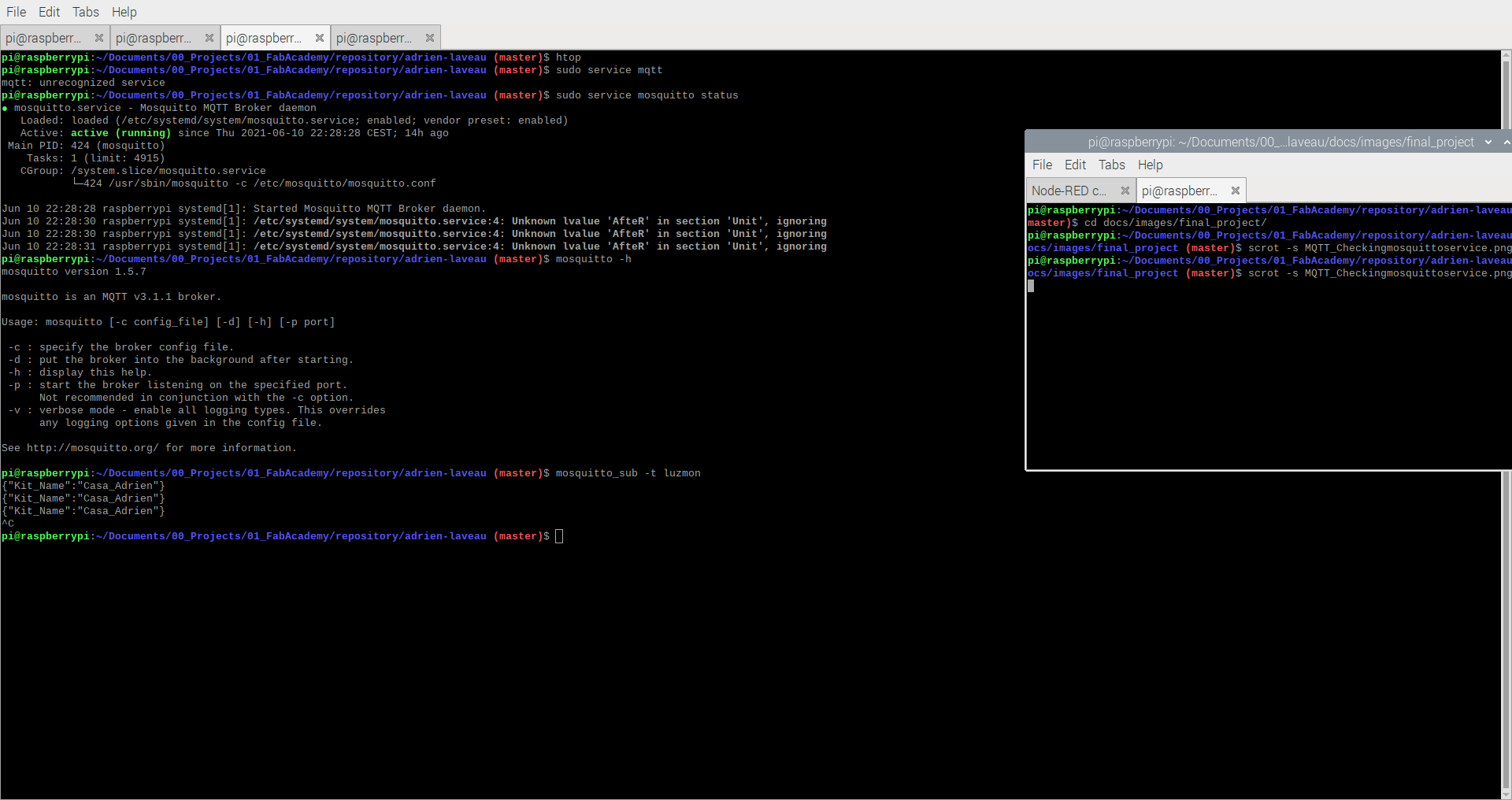
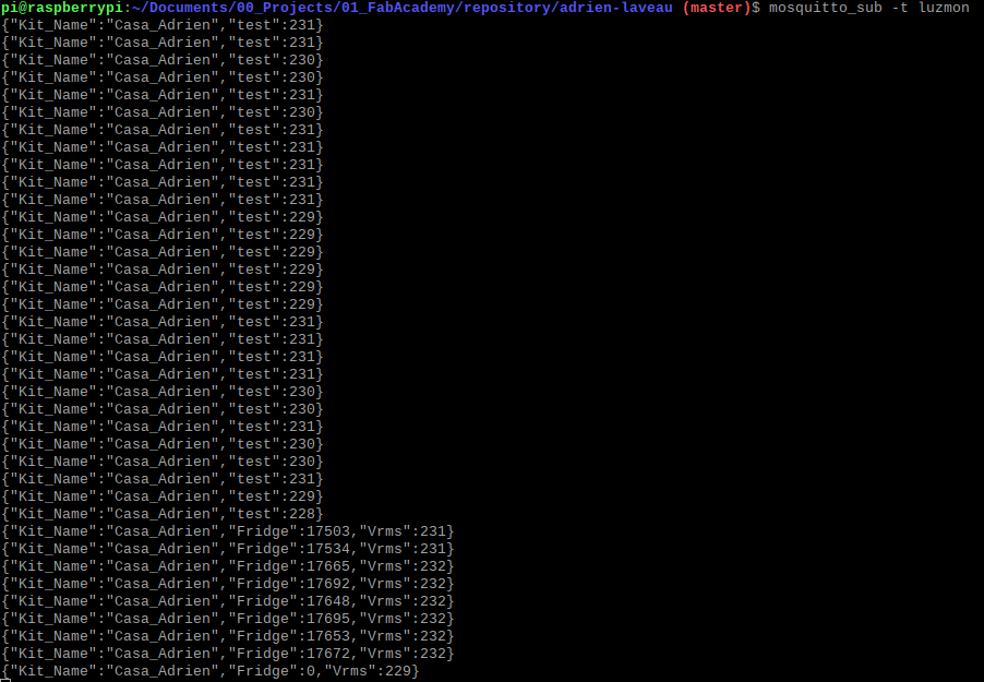
Then I run the mosquitto_sub.
mosquitto_sub -t luzmon
I get the results I wanted !
Data flow in NODE-Red
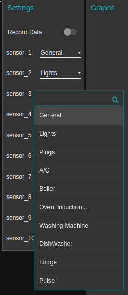
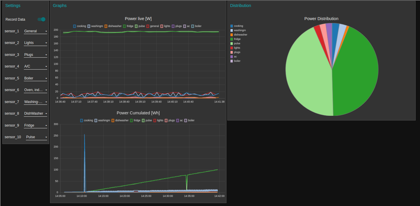
Origine of data
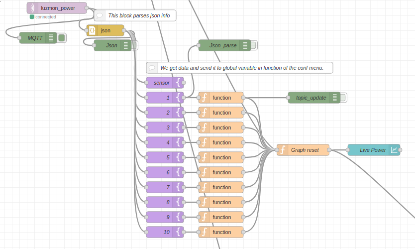
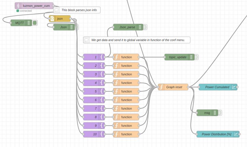
First of all the user has to give the information of which sensor is connected to which appliance. This is done thanks to a list of drop-down menu which relates sensors and appliance.
One the two images below are shown the flow and the equivalent interface.
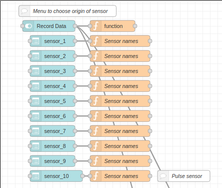
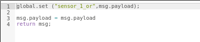
In the flow I edited the purple nodes and added the code shown in the image below to store the information of the switch in a global variable that will be used later on to properly link data and legend.
MQTT/Graph
Then we have to get the information sent by the ESP32 to the MQTT broker. This is done using the following nodes :
| Node | Role |
|---|---|
 |
This node allows he user to subscribe the flow to a specific topic |
 |
In this node we tell Node-red to interpret the message as a json string and convert it to a json object |
 |
Now that we have a json object we select the part we are interested in (here one of the current sensor value) |
 |
Using the switches values defined before we save the data in a specific global variable and to add a topic to the message based on the switch position (for the legend of the graph) |
 |
This node is to reset the graph when a specific button is slided (to remove garbage data while I am developing) |
 |
Here we plot the graph (payload = value and topic = legend) |
Theses nodes once in my flow are presented below :
Database
Investigation
Before starting the coding I had to think on how to use the database to store the data.
Now I have to organize the data knowing that in the future the data will be sent :
- from different home
- from different LuzMon Kit
- the “number” of the sensor will not always have the same info
- I will create a fixed list of possible appliances based on my home example :
- General
- Lights
- Plugs
- AC
- Boiler
- Cooking
- Washing Machine
- Fridge
- Dishwasher
In the picture below I show how I used influxDB to create the databases.
CREATE DATABASE [name of database]
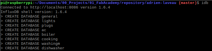
After reading a bit more about how InlfuxDB and TimeSeries work I realized that my organization is the worst I could have chosen. My understanding of the database is the following :
INFLUXDB
├── Database 1
│   ├── Measurement 1 // it is an SQL table
│   │   |time|location|scientist|butterflies|honeybees|
│   │   |----|-------|----------|-----------|---------|
│   │   | 1  | A     |Mr.Bob    | 12        | 23      |
│   │   | 2  | B     |Mr.Pip    | 5         | 32      |
│   │   | 3  | B     |Mr.Pip    | 22        | 43      |
│   └── Measurement 2
│   │   |time|location |stationID|Humidity|Temperature|
│   │   |----|---------|---------|--------|-----------|
│   │   | 1  | Paris   |X22      | 30     | 15        |
│   │   | 2  | Paris   |B43      | 31     | 18        |
│   │   | 3  | Madrid  |M48      | 42     | 27        |
└── Database 2
    ├── Measurement 1 // it is an SQL table
    └── Measurement 2
And bit of vocabulary :
- Field keys : butterflies / honeybees
- Field values : the data
- Tag keys/value : it is an extra information on the data
Warning
Fields are not indexed. So if I have queries on the field values it can be slow. An advice from influxdb is then to pass the field as tags and tags as field.
With this information, I understood that I had created several databases instead of one database with several measurments.
My new scheme has to be as follows with one database and two measurments:
INFLUXDB
├── Database luzmon
│   ├── Measurement "PowerCumulated"
│   │   |time|general|general-current|fridge|plugs|oven|ac|sensor_ID|location|address|
│   │   |----|-------|---------------|------|-----|----|--|---------|--------|-------|
│   │   |    |       |               |      |     |    |  |         |        |       |
│   │
│   └── Measurement "Current" [optional]
│   │   |time|general|general-current|fridge|plugs|oven|ac|sensor_ID|location|address|
│   │   |----|-------|---------------|------|-----|----|--|---------|--------|-------|
│   │   |    |       |               |      |     |    |  |         |        |       |
│
└── Database 2
    ├── Measurement 1 // it is an SQL table
    └── Measurement 2
Info
To remove the database I do not want, I use the following command
show databases use luzmon_power Drop database luzmon_power
Note
- For the moment I will not fill the current database because it will be huge but still I would like to have some data current for further analysis and modeling with the goal of reducing the number of clamps. So in the future I might include it.
- I would like to add info about the max current that would be useful to adjust the electricity contract. But I will see that in a second step.
Application to NODE-Red
For the database we have the option between two different nodes of the influxDB-contrib.
Note
In InfluxDB, SQL tables are referred to as Measurements
- influxdb-out : meant to write data to 1 measurement
- influxdb-batch : meant to write data to several measurement but the data has to be structured into an object first
As I want to fill the measurements of Live Power and Cumulated Energy at the same time I used the influxdb-batch node as follows.
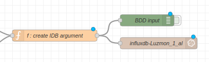
Below I present the code to prepare the data to do so. The idea is to prepare a json package that holds the measurement name, fields and tags.
    msg.payload = [
        {
            measurement: "1",
            fields: {
                Val_1: 5.1,
                Val_2: 3.2
            },
            tags:{
                sensor_ID: "1",
                location:"barcelona",
                addresse: "address_1"
            }
        },
        {
            measurement: "2",
            fields: {
                Val_1: 5.1,
                Val_2: 3.2
            },
            tags:{
                sensor_ID: "1",
                location:"barcelona",
                addresse: "address_1"
            }
        }
    ];

    msg.payload=msg.payload
Code for Data preparation for database
I use the code to input the data in the database and also to give the proper name to each data using the value of the dropdown menu of my interface.
var record_data = global.get("record_data");

if (record_data == 1) {

const sensor_1_or = global.get("sensor_1_or");
const sensor_2_or = global.get("sensor_2_or");
const sensor_3_or = global.get("sensor_3_or");
const sensor_4_or = global.get("sensor_4_or");
const sensor_5_or = global.get("sensor_5_or");
const sensor_6_or = global.get("sensor_6_or");
const sensor_7_or = global.get("sensor_7_or");
const sensor_8_or = global.get("sensor_8_or");
const sensor_9_or = global.get("sensor_9_or");
const sensor_10_or = global.get("sensor_10_or");

var sensor_1_pow_val = global.get("sensor_1_pow_val");
var sensor_2_pow_val = global.get("sensor_2_pow_val");
var sensor_3_pow_val = global.get("sensor_3_pow_val");
var sensor_4_pow_val = global.get("sensor_4_pow_val");
var sensor_5_pow_val = global.get("sensor_5_pow_val");
var sensor_6_pow_val = global.get("sensor_6_pow_val");
var sensor_7_pow_val = global.get("sensor_7_pow_val");
var sensor_8_pow_val = global.get("sensor_8_pow_val");
var sensor_9_pow_val = global.get("sensor_9_pow_val");
var sensor_10_pow_val = global.get("sensor_10_pow_val");

var sensor_1_pow_cum_val = global.get("sensor_1_pow_cum_val");
var sensor_2_pow_cum_val = global.get("sensor_2_pow_cum_val");
var sensor_3_pow_cum_val = global.get("sensor_3_pow_cum_val");
var sensor_4_pow_cum_val = global.get("sensor_4_pow_cum_val");
var sensor_5_pow_cum_val = global.get("sensor_5_pow_cum_val");
var sensor_6_pow_cum_val = global.get("sensor_6_pow_cum_val");
var sensor_7_pow_cum_val = global.get("sensor_7_pow_cum_val");
var sensor_8_pow_cum_val = global.get("sensor_8_pow_cum_val");
var sensor_9_pow_cum_val = global.get("sensor_9_pow_cum_val");
var sensor_10_pow_cum_val = global.get("sensor_10_pow_cum_val");

msg.payload = [
    {
        measurement: "power",
        fields: {
            [sensor_1_or]: sensor_1_pow_val[0],
            [sensor_2_or]: sensor_2_pow_val[0],
            [sensor_3_or]: sensor_3_pow_val[0],
            [sensor_4_or]: sensor_4_pow_val[0],
            [sensor_5_or]: sensor_5_pow_val[0],
            [sensor_6_or]: sensor_6_pow_val[0],
            [sensor_7_or]: sensor_7_pow_val[0],
            [sensor_8_or]: sensor_8_pow_val[0],
            [sensor_9_or]: sensor_9_pow_val[0],
            [sensor_10_or]: sensor_10_pow_val[0]
        },
        tags:{
            sensor_ID: "1",
            location:"barcelona",
            addresse: "address_1"
        }
    },
    {
        measurement: "power_cum",
        fields: {
            [sensor_1_or]: sensor_1_pow_cum_val[0],
            [sensor_2_or]: sensor_2_pow_cum_val[0],
            [sensor_3_or]: sensor_3_pow_cum_val[0],
            [sensor_4_or]: sensor_4_pow_cum_val[0],
            [sensor_5_or]: sensor_5_pow_cum_val[0],
            [sensor_6_or]: sensor_6_pow_cum_val[0],
            [sensor_7_or]: sensor_7_pow_cum_val[0],
            [sensor_8_or]: sensor_8_pow_cum_val[0],
            [sensor_9_or]: sensor_9_pow_cum_val[0],
            [sensor_10_or]: sensor_10_pow_cum_val[0]
        },
        tags:{
            sensor_ID: "1",
            location:"barcelona",
            addresse: "address_1"
        }
    }
];

msg.payload=msg.payload
return msg;

}
Final Result - Temporary :)
At the moment with the actual configuration I can see the data live and cumulated but with some errors due to electrical connextion that I have to figure out.
Saving into the database does not work really well because the data arrives in a separate fashion through MQTT.
I have to find a way to group all the data before saving it into the database.
OLED
Objective
Now that the data flow is active I want to use the OLED screen to show some partial data to the user. I will have to program extra code to the ESP32 for this part. My goals are the following :
- STEP 1 : show live data of current consumption on the screen
- STEP 2 : show a replica of the Raspberry interface graph on the screen as shown below
- STEP 3 : show data depending on the user request with the buttons (change the range of the graphs for example)
Debugging
Note
This part is a bit messy because this is the notes I took during the debbuging. I let them as such for reference because it was interesting to see the process. But the important part is conclusion I made from the debugging * I2C pins of the ESP32 were wrong * the Screen works at 3.3V (a little bit less bright) * DC pin has to be put to ground * RST pin can be pulled-up
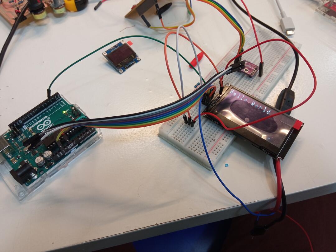
To start using the OLED screen I first used the same small OLED screen as in my input week with the following code as proof of concept for the library.
The library I plan to used is called U8g2 and allows to create complicated output on OLED scren and is recommanded for mine. To got step by step, a simpler version of this library is called u8x8
I use the code of u8x8 simple library
    #include <U8x8lib.h>
    #include <Wire.h>

    U8X8_SSD1306_128X64_ALT0_HW_I2C u8x8(U8X8_PIN_NONE);

    void setup() {
      // put your setup code here, to run once:
      pinMode(3, OUTPUT);
      digitalWrite(3, LOW);
      delay(500);
      digitalWrite(3, HIGH);
      u8x8.begin();
      //u8x8.setFlipMode(1);
    }

    void loop() {
      // put your main code here, to run repeatedly:
      u8x8.setFont(u8x8_font_5x7_f);
      u8x8.setCursor(0, 0);
      u8x8.print("Hello World");
      delay(1000);

    }
I was able to make it work easily and print the “Hello World” using a bread board.
After that I used the big screen with same code and same bread board and it did not work.
I realized at that moment that the screen works on 5V and that I need a level shifter.
After the installation of the level shifter it still does not work.
Talking with my instructor I realize thatmaybe I have to do something with the DC pin. I find on a web that I have to put it to ground. It works !!
Not lets try the level shifter with my OK ESP32 because up to know everything was done using the Arduinio to remove the ESP from the equation. In fact I tested at 3.3v without level shifter and it works. So I might let everything at 3.3v
So i might use the 5v pin to bring my reset signal. But after some tests I checked that having the reset pin pull-up also works. I might have some issue to refresh the screen but I tried to have it running a few minutes with different screen displays and it worked fine.
But the conclusion is : - reset pin pulled up - 3.3v alimentation
Now I have to transfer this to the display board of my final project.
Some issues in the design wrong I2C pins I had to connect CS and D/C to negative to make it work.
Now I test if I can use the pin 7 and 8 of the ESP as SW I2C. It works with GPIO as follows
define PIN_SDA 27
define PIN_SCL 25
Now I want to do it with pins 7 and 8 which are not supposed to accept it.
Does not work. I tried with 12 and 14, does not work either … it would be better for board simplicity.
I use SDA 33 and SCL 32. Also I made a mistake on the display board and 2 pins SDA and SCL are inverted on the display side.
Conclusion : After all the debugging on the ESP32 I realized that the issue came from a false contact between the display board and the OLED screen. So I made a new board to start fresh and when I have time I will go on with the implementation.
Usage
This part is not finished for the moment but was not compulsory for my project. Still I will go on documenting it when I can finally make it work.
Improvements
ATMEGA
- Calibrated current sensors
ESP32
- Send MQTT message info by info instead of board by board
- OLED communication to be done
RaspberryPi
- Monitor live current to reduce number of clamps
- Monitor peak current to adapt my energy contract
- Improve data packaging to save data to database