7. Computer-Controlled Machining
Group assignment
Design
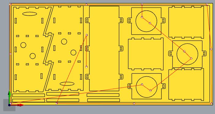
For the group assignment we started from a file from last year’s Barcelona student
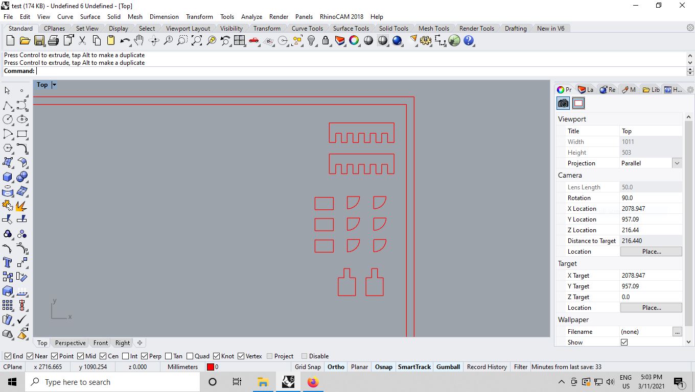
But as some of us had the idea of using rodes of making flexible parts we
improved the file adding more tests and cutting parameters.
Parameters
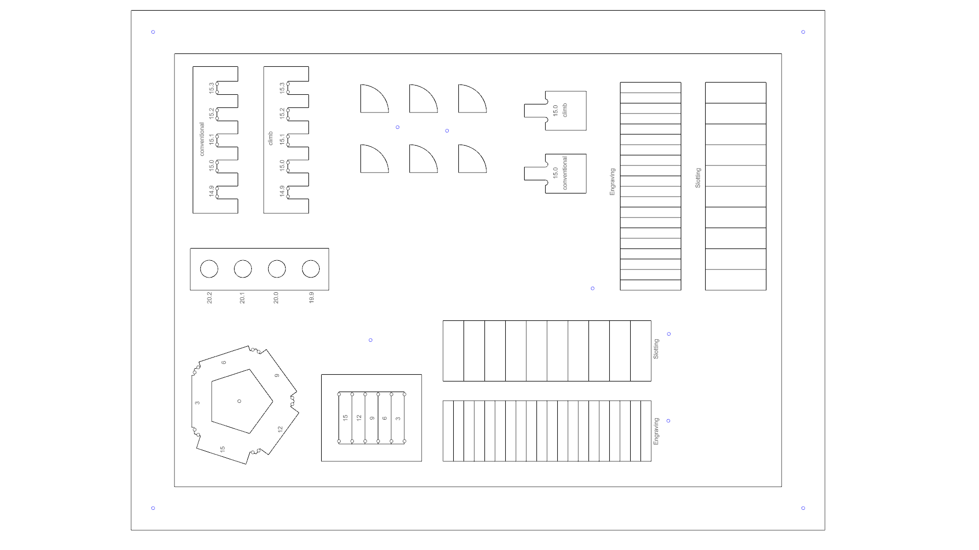
Below is presented each step for preparing the file to cut.
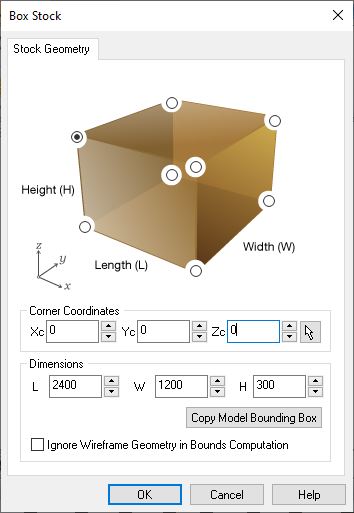
The stock was a scrap we took to avoid wasting wood. We basically have to set-up : * Lenght * Width * Height * Confirm that origin is on the top –> this is important !
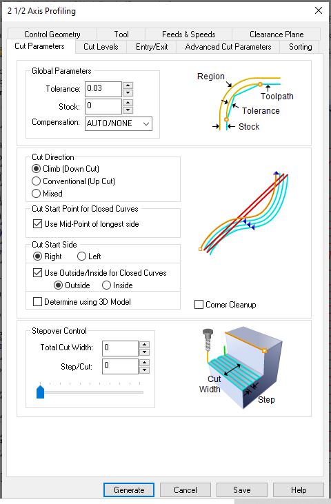
For the cutting parameters the important values we entered are the following ones :
Tolerance : it is set as 0.03, we can go up to 0.01. It is the margin
of error we accept for the computation of the cutting path.
* Cut direction : we set most of the cutting as climb because for the
plywood we use it is the recommended one as the material is soft (not
too much) and we use a down cut* end mill.
* Start point : mid-point of the longest is good to avoid starting on
a point that might need detailed cut.
* Outside/inside : this parameter is really important to explain the software
whether you are doing an incut our an outcut.
* Stepover : when engraving this is how much of the previous path will
be stepover. The higher the better for surface quality but the cutting
time will increase in proportion. Usually around 30% is fine. (Here we
have 0 because we are cutting)
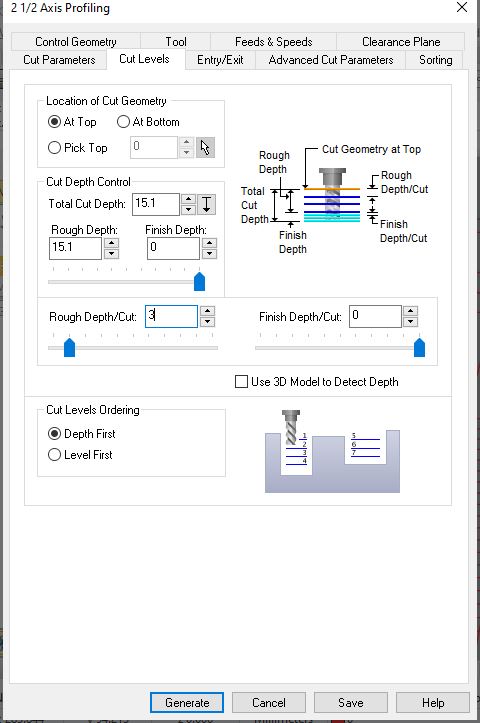
The cuts level will explain the software how to place the cut with respect to the stock. * Localtion of cut geometry : at top ! Important otherwise you risk to cut the sacrificial board or break the end mill. * Total cut depth : it is the height of your stock + a margin. usually +0.1mm to be sure to fully cut the stock. * Rough depth/cut : is how you will cut along Z axis for each pass. It should be approximately half of the tool diameter. In our case 3mm. If the board is not a multiple of the cut depth, you can add 0.1 or 0.2 mm to avoid a last cut of 0.1mm that would take a lot of time. * Cut levels ordering : is used to confirm we want to cut hole/hole by selecting depth first.
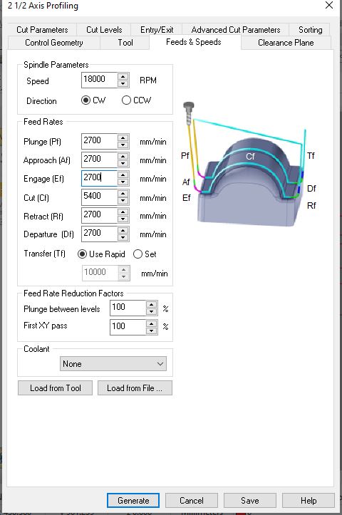
This part is about chips and speed ! To define the correct parameters
to be used to mill we used the chip equation learnt during our lecture.
chip load = SPEED [mm/min] / ( RPM * Flute number)
Chip load, RPM and Flute number being inputs, we will deduce the speed as follows : SPEED [mm/min] = chip load * RPM * Flute number
Having the following info :
chipload:For plywood we saw that the recommanded chip load ranges from 0.28 to 0.33
* RPM*: From 18000 to 22000 rpm
It gives us the following possible linear speed : * 0.28 * 18000 * 1 = 5040 mm/mn * 0.33 * 22000 * 1 = 7260 mm/mn
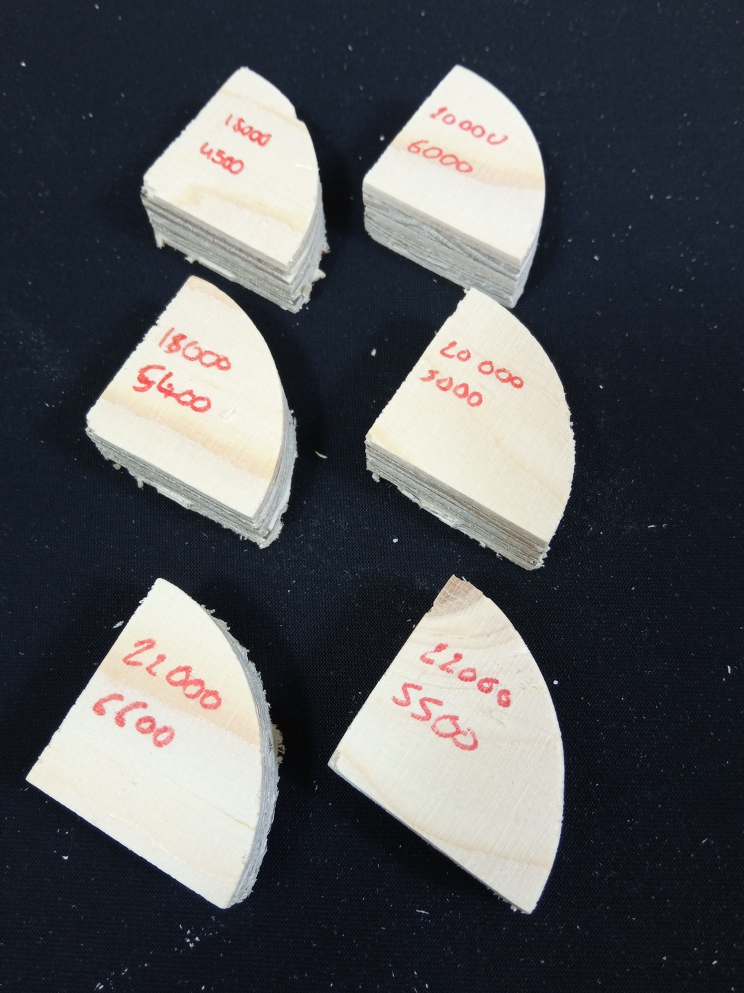
Following our instructors recommandation we should target the lower range of ship load for our set up so we will test the following combinations of RPM - Feed Rate : * 18000 - 4500 * 18000 - 5400 -> image below is for this setup * 20000 - 5000 * 20000 - 6000 * 22000 - 5500 * 22000 - 6600
The rest of speeds should be setup at approximately half the cutting speed.
Results
The result of our group assignment is presented below and guided us toward the best solution for our design.
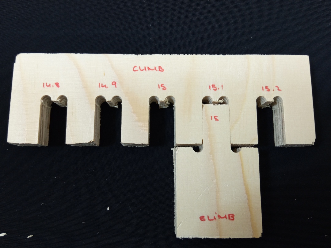
The RPM/FeedRate test shows that the lower the speed the better the result.
It seemed that a speed of 5000mm/min at 20000rpm was pretty convenient. From
their experience the instructors recommended us to use a setting of 18000rpm
at a feed rate of 5400mm/min.
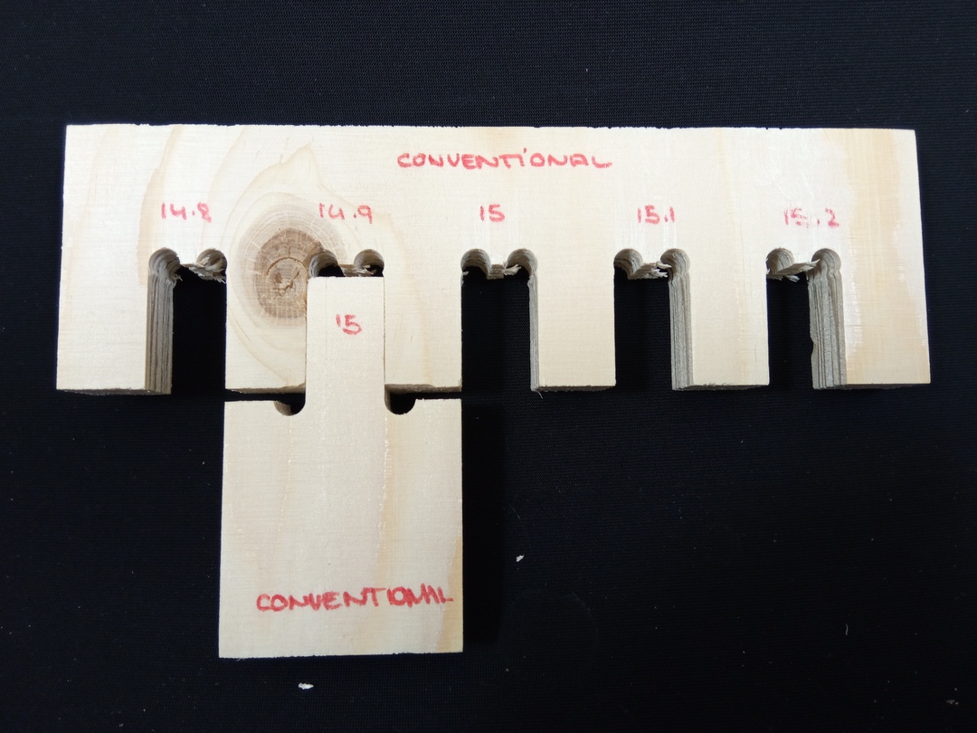
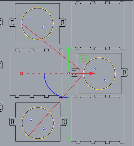
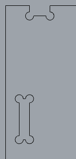
We then tested the clearance needed for pressfit joints. To do so we use the
same test as for the kerf evaluation durign the laser cutting week. Starting
from the height of the stock, we vary the size of the notch.
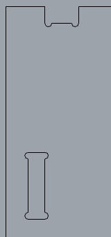
We laso used this test to evaluate the difference between conventional and
climb cut.
We opted for the climb method because the tool we are using is a down-cut (which
helps protecting the top layer of the ply-wood,the lower part is not so clean)
is meant to be used with climb cut.
Testing the force needed to mount the 15mm male part in the notches convinced
me that no clearance was needed. The force was reasonable to hold without
glue or screws.
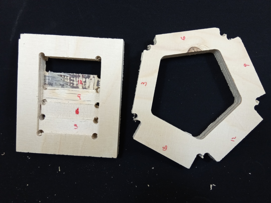
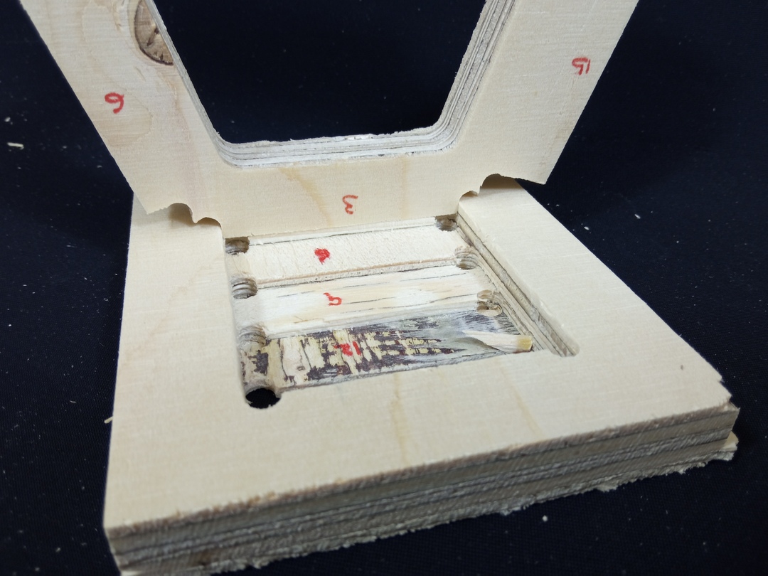
The pocket accuracy was meant to find out how good is our CNC at creating pocket and to see if any kind of clearance was needed. We had a small issue because the reference plane to see if the pocket was of the required size, was not touching the female part. But still it seemed that no vertical clearance was required.
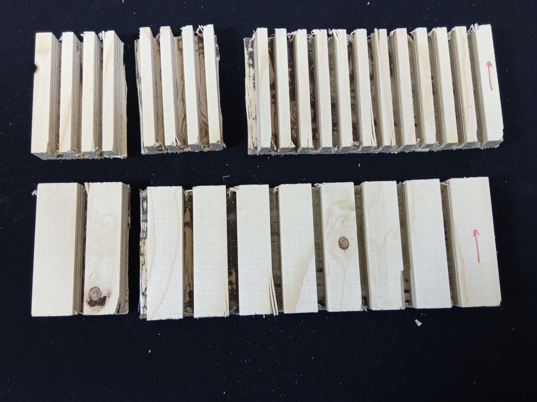
This final test was to evaluate the possibility of make flexible part for my personal assignment. We designed it so that just a single layer of plywood would be left after the cut. The output was not really convincing. * Cuts with the fiber direction : it brakes immedialty * Cuts perpendicular with fiber direction : it did not bend a lot
So based on that I decided not to use this kind of flexible joints in my design.
Personal assignment
Design
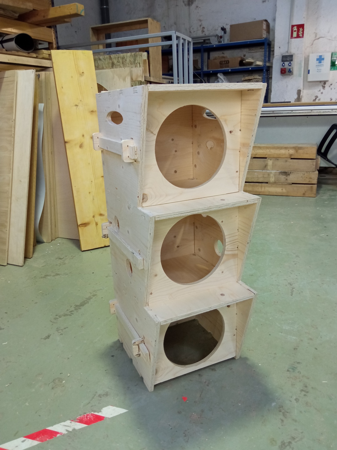
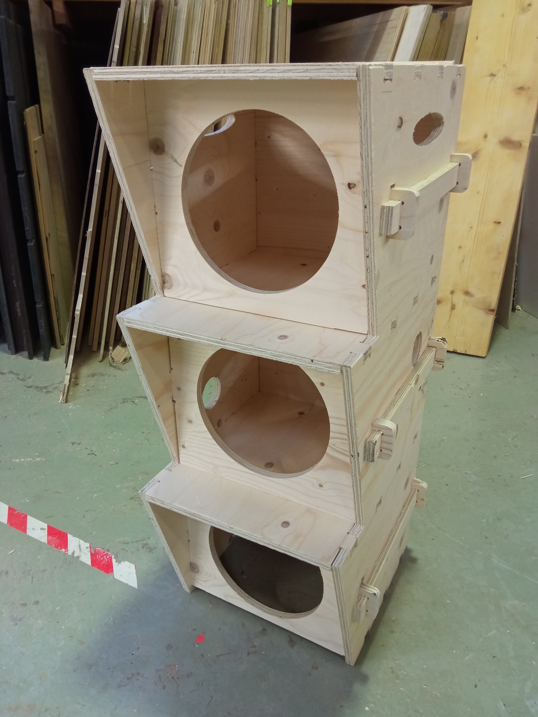
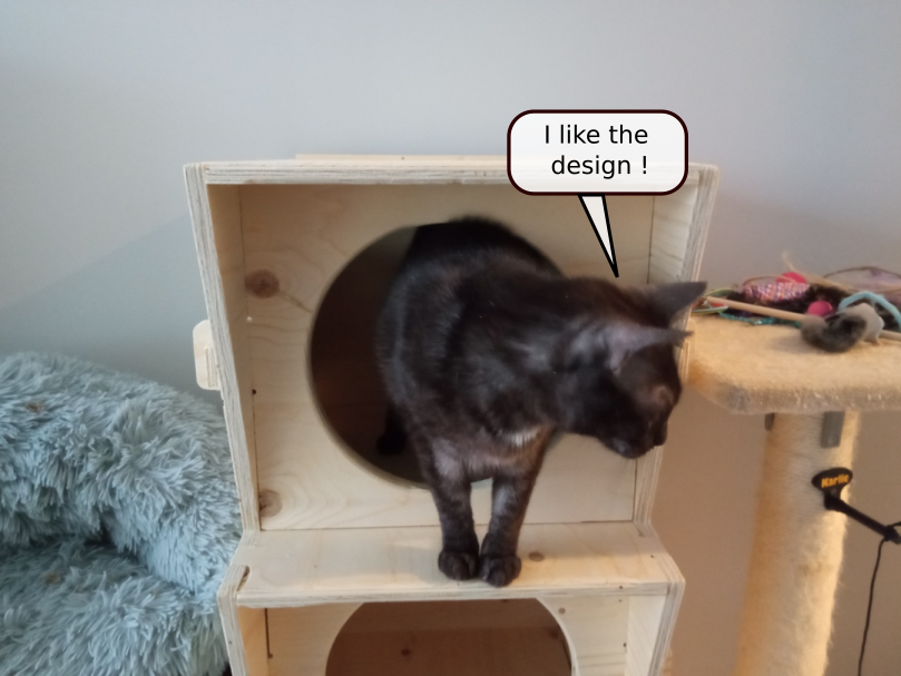
My personal assignment is about making a small shelter for cats with the rule No Glue no Screw.
The final 3D part looks like this one :
Some errors I made during the design and corrected
- I took the tool diameter for the radius.
- The holes to give clearance for joints were not placed properly see below
- As I worked a lot on the joint there was some open curves not belonging to the design
- One part of my design was moved a little bit out of the XY plane, I did not see it during the preparation… explanations below
Parameters
My setup was a bit simpler than the group assignment because I had less cutting parameters. Still I made some mistakes from which I learnt …
RhinoCAM
I have not talked about the software I used for this week assignments.
We used a module called RhinoCAM based on Rhino. The main reason to use
it is that the pre-processor (code that converts our parameters into
GCODE) for the machine was available (created by Eduardo Chamorro one
of our instructors) on this software.
I wanted to use freecad which has a software to do that but I am still
having issue with FREECAD at the moment I write this page, and I am
not sure that I will find the post-processor for our CNC.
I describe below each cutting parameters in the order I cut them on the machine.
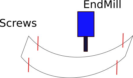
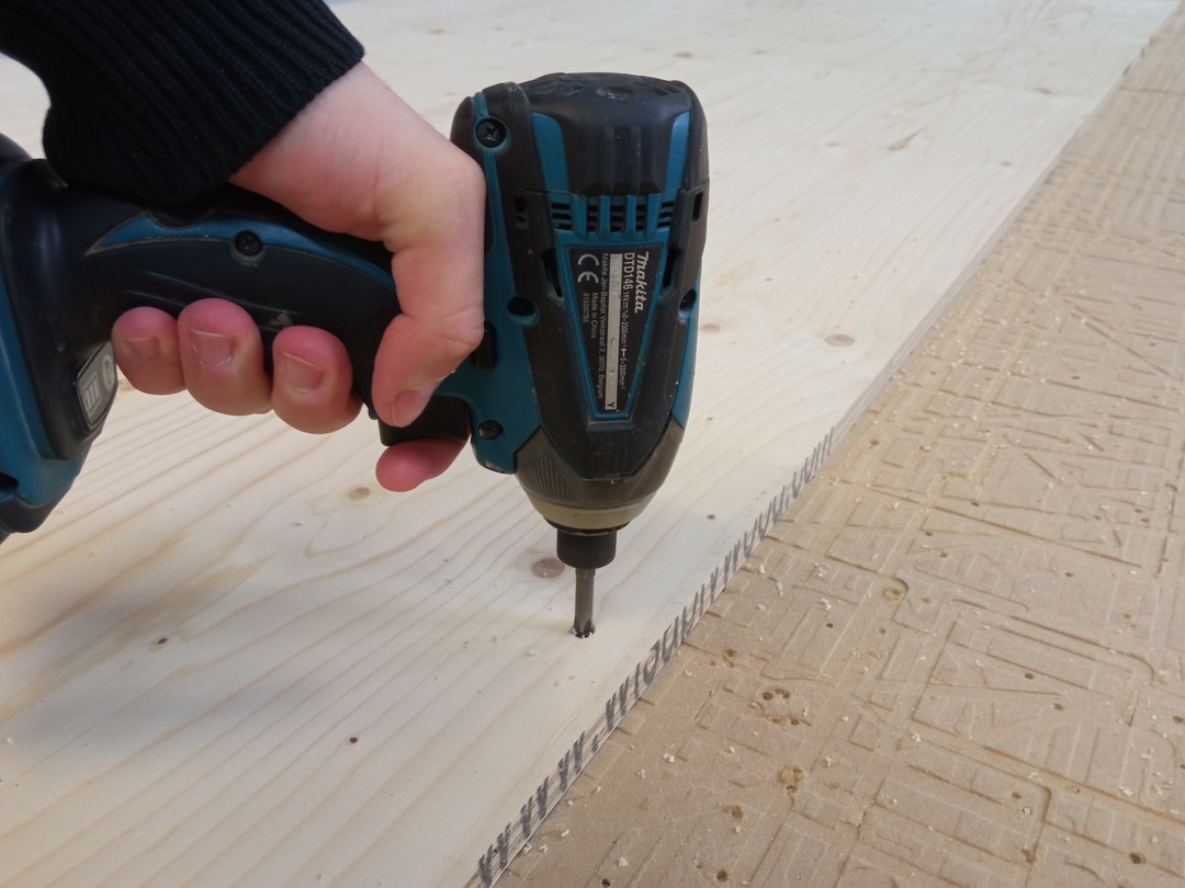
This part is not mandatory but makes the operation safer. The idea is that when we screw the stock on the sacrifciial plate we are never sure that the screws are not in a place where we will cut later. To avoid inutil risk of breaking our end-mill, we include the screws in the design and engrave a small mark where the screws should go.
Warning
Do not forget to redo the Z-zero after screwing.
The parameters I used for that were :
| Parameter | Unit | Value |
|---|---|---|
| FeedRate | mm/min | 4500 |
| RPM | rpm | 18000 |
| Cut depth | mm | 3 |
| Other speeds | mm/min | 2250 |
For this part I wanted to test something to make the final result cleaner.
Indeed when a part is cut we will see in the next tab that some tabs must
be placed to avoid the part flying away.
Well, to avoid the tabs which have the drawback of leaving marks, I
decided to screw the inner part of my doors opening.
It is important to put 2 screws ! With just 1 screw the part can rotate around it.
| Parameter | Unit | Value |
|---|---|---|
| FeedRate | mm/min | 4500 |
| RPM | rpm | 18000 |
| Cut depth | mm | 15.3 |
| Cut depth per pass | mm | 3.3 |
| Cut direction | - | Climb |
| tabs | No tabs | |
| Cutting zone | - | Inside |
| Approach | - | Following the trace |
| Exit | - | Vertical - to avoid hitting other parts |
| Cutting order | By holes - not by level | |
| Other speeds | mm/min | 2250 |
For details of the order of magnitude of the tool diameter (3,4,5 times the tool diameter) it is better to do pocketing even if you cut the whole material because there will not be space for the tabs. So in my case all the joints holes were done by pocketting.
Go easy on pocketing … it takes time !
| Parameter | Unit | Value |
|---|---|---|
| FeedRate | mm/min | 4500 |
| RPM | rpm | 18000 |
| Cut depth | mm | 15.3 |
| Cut depth per pass | mm | 3.3 |
| Cut direction | - | Climb |
| Overlay | - | 30% - tradeoff between speed & quality |
| Cutting order | By holes - not by level | |
| Other speeds | mm/min | 2250 |

The final step comes. All the geometry that has to be cut from outside is cut in this step. It means, the outside part of the main boards and the internal details big enough to be hold with tabs.
| Parameter | Unit | Value |
|---|---|---|
| FeedRate | mm/min | 4500 |
| RPM | rpm | 18000 |
| Cut depth | mm | 15.3 |
| Cut depth per pass | mm | 3.3 |
| Cut direction | - | Climb |
| tabs | 3*4mm tabds | |
| Cutting zone | - | Outside |
| Approach | - | Following the trace |
| Exit | - | Vertical - to avoid hitting other parts |
| Cutting order | By holes - not by level | |
| Other speeds | mm/min | 2250 |
As for the inside cut and the pocketting, the Cut depth per pass is a bit more than 3mm to avoid having a long last cutting phase for just 3mm.

Let’s Cut
Prepare the cut
Placing the stock
As for laser cutting, always place the stock with the corners bending upward. Not doing so might imply errors of the order or centimeters in the final design because the center of the board will move as you mill it.
The Zeros
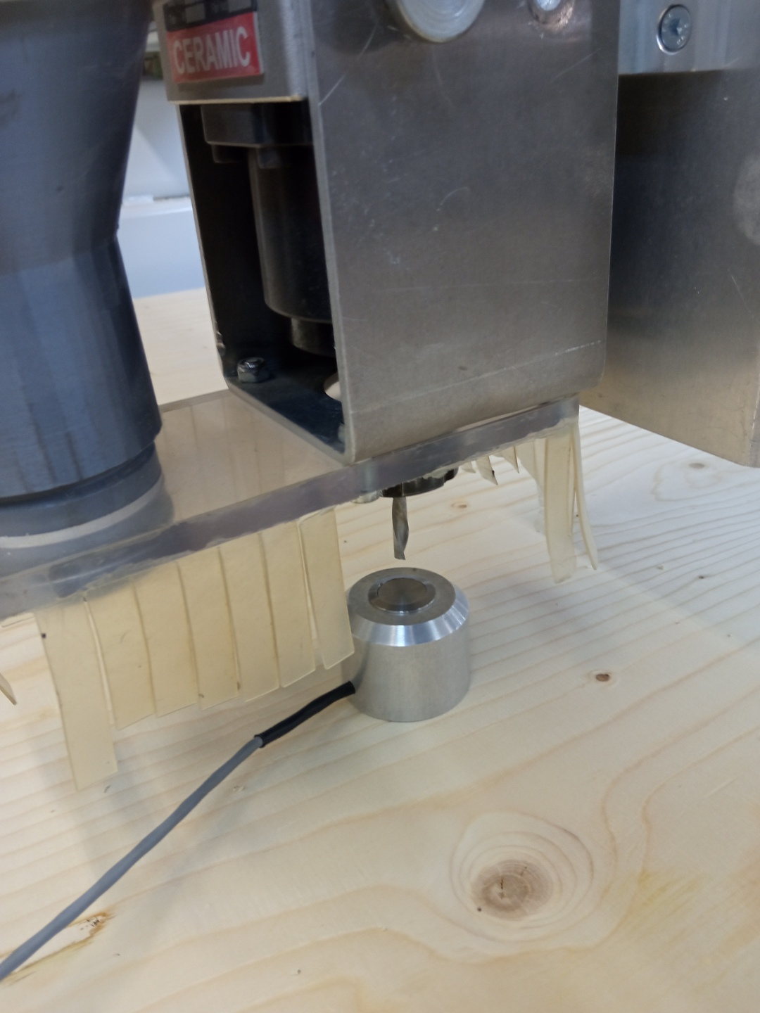
Before cutting, the machine needs to be setup. The main goal of this phase is for the machine to know where it actually is. Indeed when the machine is off, the bridge, motor, z axis might have been moved manually. Or even the tool that is installed does not always have the same lenght. The machine must know that.
To do so we do what is called the zero of the axis. It is done following
those steps :
1. Homing the machine : it will find its own zero using proximity sensors
1. Indicating the X/Y zero of the stock : we move the bridge with the software
until the center of the end-mill reach the desired 0 of the stock.
1. Indicating the Z zero of the stock
1. Place the end mill at approx X:20cm & Y:20cm
1. Place the Zprobe below the end-mill. Be 100% to be below otherwise you will destroy the end-mill andthe probe
1. Run the Z zero macro and the software will lower the end-mill until pressing the button of the Z probe
1. The zero is done
1. Always repeat the Z zero once the material is screwed
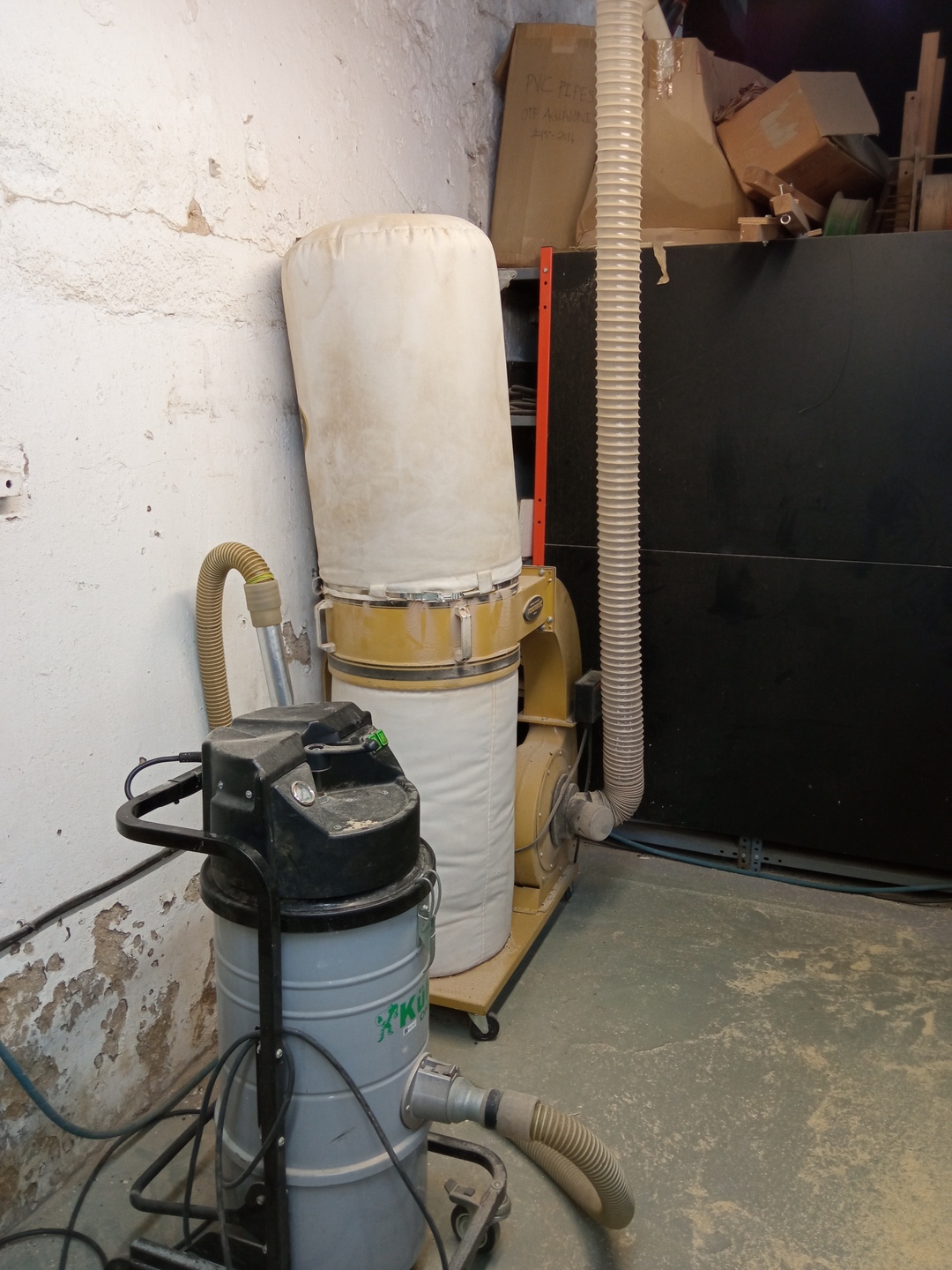
Dust collector
Always use the ventilation when cutting to save a bit of cleaning afterwards ! This machine goes directly next to the end-mill to remove as much cutting chips as possible.
Cutting
When the cutting starts 3 things are important to check for the safety of the machine.
Be sure to know where the emergency stop is !
As soon as possible, check that the minimum Z position is equal to minus your stock height to be sure you are not cutting too deep due to a faulty design or wrong parameters.
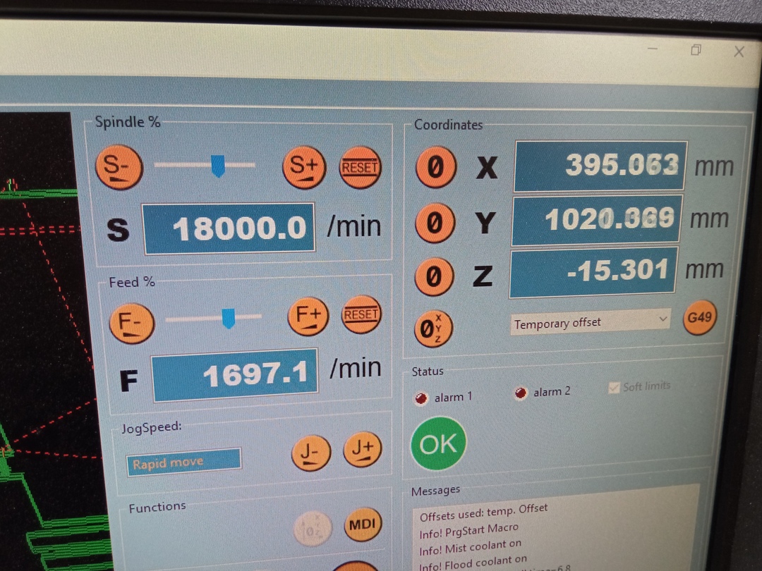
Run the machine 3mn, stops and touch the end-mill with your fingers, it should not be too hot.
Then wait for the cut to go on. Do not hesitate to confirm that what happens
in front of you is what you expected.
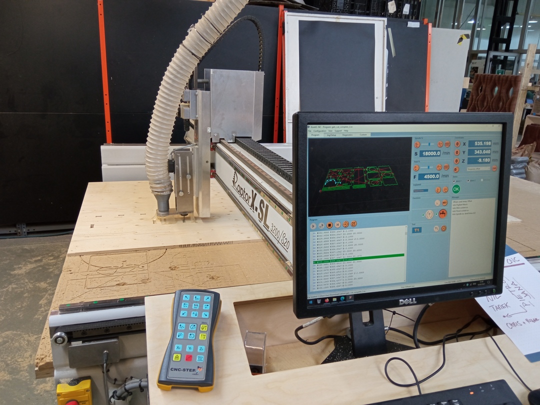
This is how our CNC looks like at FabLab Barcelona.
The cut lasted 1h. It was a really good move not to pocket all the holes. It would have been easily 2hrs if I had done it.
Details
Once the cutting is done, I tried to investigate the cutting quality purely linked to the milling parameters.
A good cut gives good chips. So when the cutting is on going if you have the occasion to check the cutting residue, it should not be dusty neither too big. On the picture below you can see the result of my cut which I think is what one should expect.
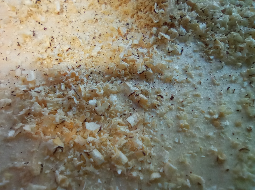
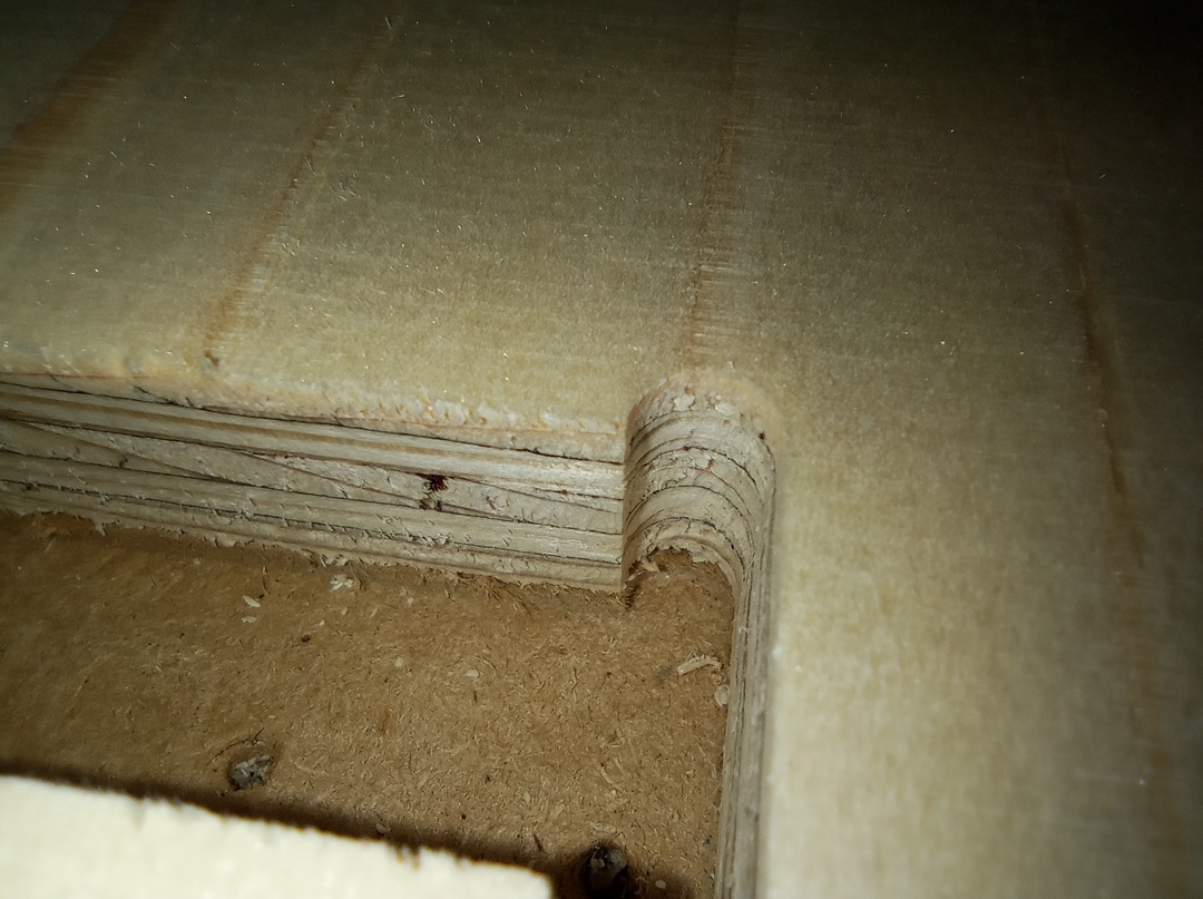
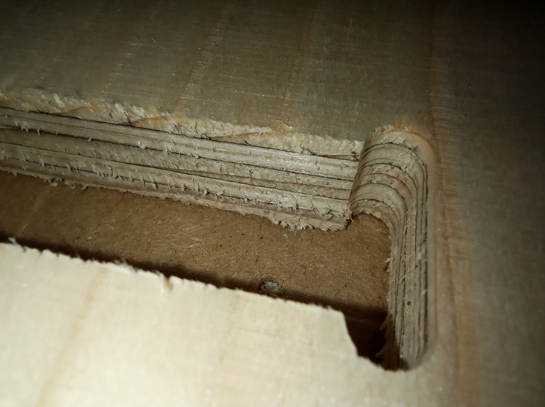
One can see on the picture below that the results of the milling is much better when cutting in the direction of the wood fiber. When cutting perpendicular to it, the upper part gets torn apart. And it would be much worse using an up-cut end-mill.
The pocketing of the joints can be seen below. No issue here. The result
is as expected.
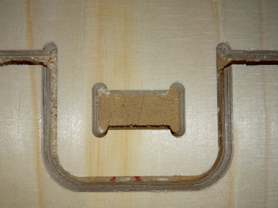
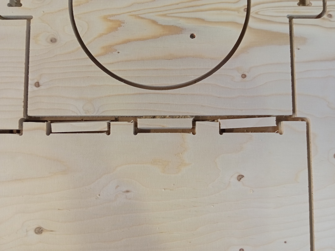
The tabs are also present and were high enough to hold the parts in place.
Warning
The tab height is computed from the lowest part you cut ! So do not take too much margin on the cutting depth or compensate on your tab height.
Issues
As one can see in the previous section, the cutting went almost ok if we consider
the cutting parameters.
Now I had two main issues.
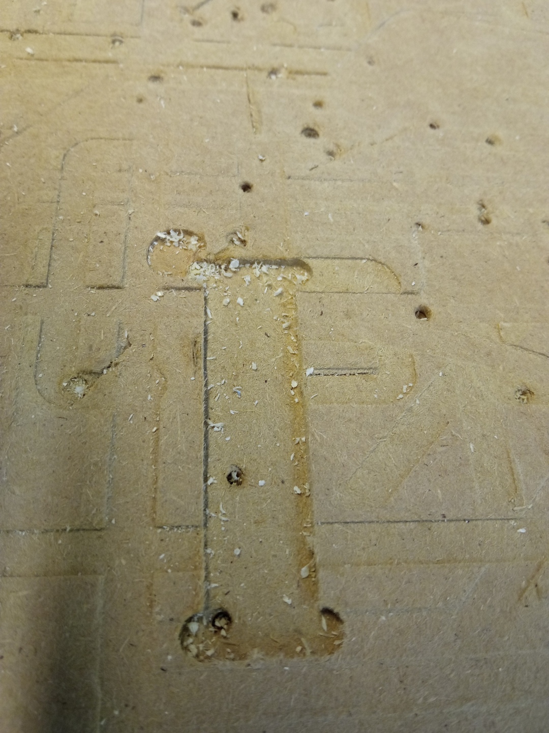
3D curve
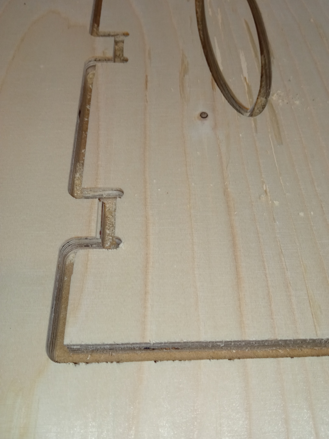
Due to a probable manipulation mistake, one the curve of my design was not lying in the XY plane and as a consequence I started to cut too deep in the sacrificial board as shown in the pictures below.
The proof of my mistake :
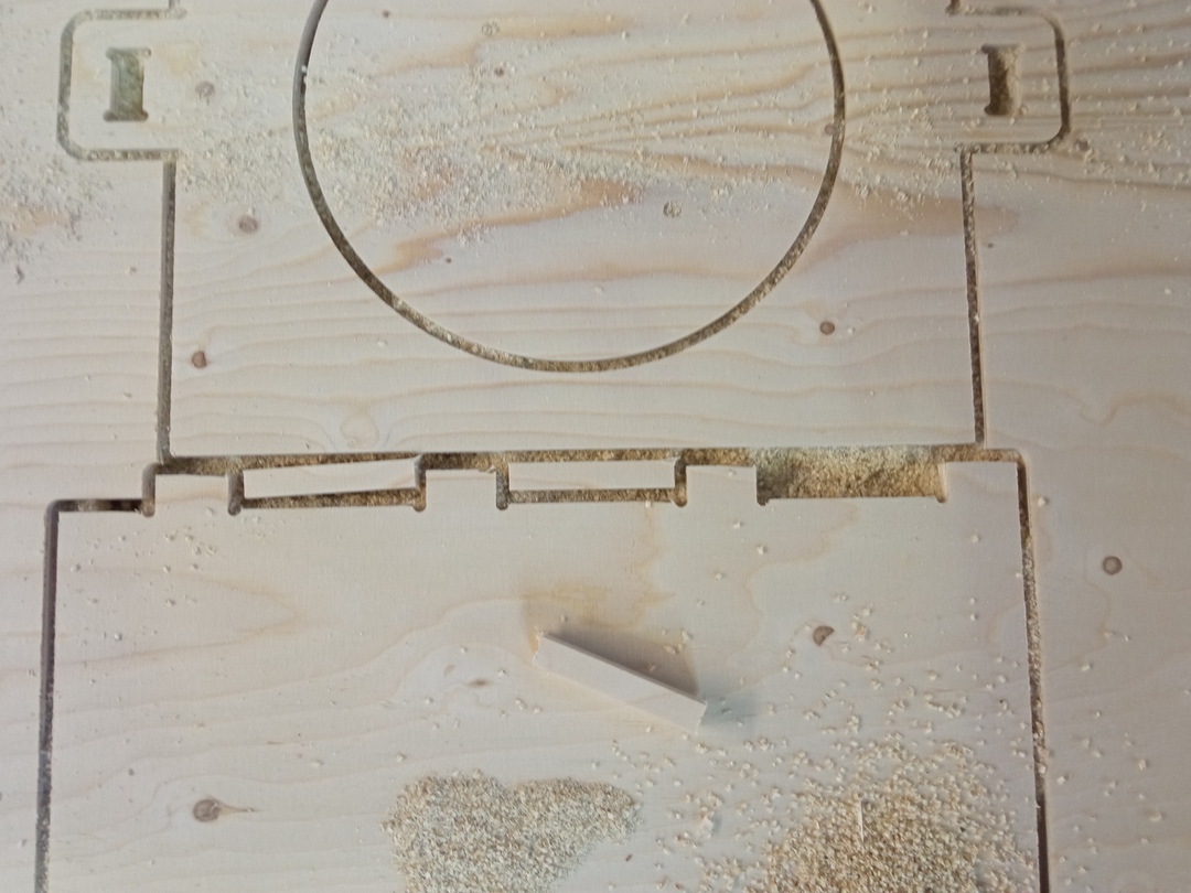
Distance between parts
The distance between two parts must be bigger than 2 times the tool diameter. 3 times is a good order of magnitude.
In my case I checked that but forgot two parts and you can see the results below. It is a potential hazard and in my case luckily one the free parts was sucked by the dust cleaner but it could have flown away.
Final results
After all that work I could finally mount the parts together !
And as any product, a quality check had to be done :

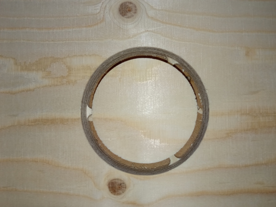
Joints clearance
As one can see below, I made some mistakes in my first design and had to adapt the joint clearance so that the end mill can pass where I want. I also made an unforgivable mistake between radius and diamter because I did not check what Rhino was asking (radius) when creating a circle. I also made the contact surface a bit bigger to avoid matting too much the material.
Files
- Group Assignment
- In the archive are the 3dm file and the NC file. One should regenerate the NC file for reuse.
- Personal Assignment