12. Outputs
Group assignment
For the group assignment we measured the electrical consumtpion of our setup.
The table below sums up the study.
| Setup | LCD Panel | OLED 64*128pix | LED RGB (144 LEDS) | Small DC motor | |
|---|---|---|---|---|---|
| Picture |  |
 |
 |
||
| Electrical Consumption [mA] | 20 | XXX | 170-800 | 1100 |
Info
For the LCD reading at the datasheet it seems the current consumption is around 600uA so there is a big difference with what we measured. It seems it comes from the backlight LED. If I find the time I will measured with and without the backlight to see the difference.
Personal assignment
For this week assignment I want to share insight with the user. What a better way than using some screens ?
The 4 screen technologies available in the lab I want to use are the following ones :
- LCD
- OLED
- 7 segment display
- Paper like display
Due to availability I was only able to test the 3 first of the list.
I have worked in three steps.
- Raspberry Pi : To connect the screens and see how they behave and what is required to run them.
- ESP32 “raw” : to confirm I can run them on the ESP and that I have the libraries I need
- ESP32 + shield + all screens : I created a small video game that has
- Potentiometer as inputs for control
- Double Segment screen for points
- LCD Screen for timer and information
- OLED screen for the game
Raspberry
To run both the LCD and the OLED screen I used Python because this is a language that fits well on the raspberry.
I2C protocol
To run the I2C protocol on the raspberry I used the information available from the Luma OLED website.
Using the output of one of the command below, one can confirm if the OLED screen is detected :
$ dmesg | grep i2c $ lsmod | grep i2c
If nothing is shown (that was my case) using the raspi-config we can activate it.
sudo raspi-config
Then we have to allow the user pi to use I2C
$ sudo usermod -a -G i2c pi –> adding user
And finally we install the needed I2C tools
$ sudo apt-get install i2c-tools
Then before communicating with your hardware, you have to know the address. It can be done with the following command.
$ i2cdetect -y 1
The output looks like this. If the hardware is detected the address appears instead of the “–“.

There is also a recommandation to modify the baurate modifying the boot/config.txt file as follows.

LCD
The simple code presented below using the library I2C_LCD_DRIVER allows to send a message on the LCD display. The function take the message as argurment and the line on which to send the message.
    import I2C_LCD_driver
    from time import *

    mylcd = I2C_LCD_driver.lcd()
    mylcd.lcd_display_string("LCDs Rock  !", 1)

OLED
For the OLED I had doubt about the adress. I had the following info :
- OLED silkscreen : 0x27
- the Web : 0x3c
But the communication worked pretty well with the “web adress” and not with the “silkscreen” adress.... why ???
I found the answer here. The explanation is that the silkscreen adress contains the read/write bit and is encoded in 8bit. So this adress has too much information and cannot be used as such. That is why the “web” adress was working fine.
HelloWorld
Finally the following code allowed me to send and “Hello world” to the OLED screen
    from luma.core.interface.serial import i2c, spi, pcf8574
    from luma.core.interface.parallel import bitbang_6800
    from luma.core.render import canvas
    from luma.oled.device import ssd1306, ssd1309, ssd1325, ssd1331, sh1106, ws0010

    serial = i2c(port=1, address=0x3C)

    device = ssd1306(serial)#ssd1306(serial)

    with canvas(device) as draw:
        draw.rectangle(device.bounding_box, outline="white", fill="black")
        draw.text((30, 40), "Hello World !", fill="white")

RaspiCam
Using a set of example from luma (https://github.com/rm-hull/luma.examples) I was able to stream my raspberrypi camera on the OLED screen.
The code is available at the end of the page. I hope you will appreciate
the DIY cardboard camera support  .
.


Testing other library
I was not sure of the reference of my screen so I used other libraries and got the following result which confirmed thqt my screen is a black&white ssd1306.

ESP32
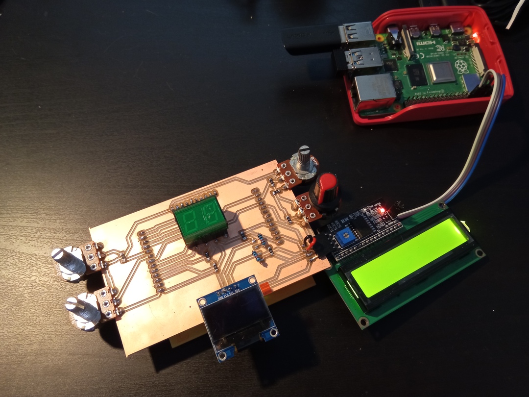
Once I was confident of the use on the ESP32 I switched to the ESP32 using the shield I created during electronic design week.

ESP32 with shield
Now that I confirmed that I can run the screens on the ESP I designed a board to receive all my components.
Schematic
To be more efficient I created a footprint of my shield to avoid pins error and to be sure that I would have the correct spacing between the shield and the ESP32 board.
The requirements for my components are the following ones.
- LCD
- 1 GND
- 1 5v
- 1 SDA (for I2C)
- 1 SCL (for I2C)
- OLED
- 1 GND
- 1 3.3v
- 1 SDA (for I2C)
- 1 SCL (for I2C)
- Potentiometer (x4 !)
- 1 GND
- 1 Ref Voltage -> 3.3v
- 1 Input
- 7segment - 2 digits
- 2 power pins
- 14 outpus
- Each output must have a current limiting resistance
Both SDA and SLA pins must have a 10kOhm pull-up resistor to avoid undesired state when no communication is on going.
The full design is presented below without all the elements that were needed because I discovered the need of the resistance afterward.

Below are presented the LCD and OLED screen that will communicate through I2C with their pull-up resistor. Then we have the 7 segment 2 digits LED matrix.
The exercise of this week was partly to use the GPIO capacity of the ESP32


PCB
To make my life easier for the routing which was pretty complicated here I used a lot of 0Ohm resistance. This way I do not have to use via and the result is equivalent and provide an easier debugging.

Production
Using the workflow learnt during fabacademy and the tools to export svg and convert them to png I could produce the following board.

Link to the pictures


Indeed 3 issue happened :
- I used normal inputs instead of ADC for the potentiometer so I had to make bridges on the board
- When switching to the PCB module I miwed up the connector of the OLED and the LED screen (which sadly does not have the same pin order). Making bridges allowed me to solve the issue
- Some of the 14 pins of the 7 segment module were connected to “input only” GPIO. For that I could not do anything at the moment so some segments are not working.
Code&Play
Once the board ready came the time to make it live. The code is available in the file section
Info
You will see reference to “Sand Game” because at first I had in mind to create a reproduction of the game where you draw in kind of a sand board with two buttons. I changed my mind while developping it but kept the name.
The code is a bit messy but I used the occasion to try several strutures and dive in the libraries.
Libraries
The libraries I used are the following ones. For the segment display I could have made my own but to go faster I used an existing one. I think it is the aim of free open source code to build on the top of what already exists.
    //Libraries
    //OLED
    #include <OLEDDisplay.h>
    #include <SSD1306I2C.h>
    #include <SSD1306Wire.h>
    //LCD
    #include <Wire.h>
    #include <LiquidCrystal_I2C.h>
    //Segment display
    include <SegmentDisplay.h>
Warning
I got confused during the development and use of the library with the
**wire” library because as both the OLED and LCD are I2C components, both
their library call and initialize the wire library and even with different
pins.
It was a bit tricky for me to find and understand. So libraries are cool
but it is important to :
* read the readme
* have a basic understanding of what they do
In some cases, the library provide functions that allow to acces an internal library. Example with SSD1306Wire.h which has the class SSD1306Wire in which the pin SDL and SLC can be provided in the following way :
SSD1306Wire display(OLED_ADDR, OLED_SDA, OLED_SCL);
Constant definition
The following tabs present my constant definition that I tried to make as clear as possible for debugging purpose. It includes pins and adresses and even screen resolution for the OLED
I made my best to give consice enough name but still that mean something to me to interact in an easier way in the code.
    //OLED related variables
    #define OLED_ADDR   0x3c
    #define OLED_SDA    21
    #define OLED_SCL    22
    #define OLED_X_res  64
    #define OLED_Y_res  128
For the LCD only the I2C address was needed as the pin for SDA and SCL are shared with the OLED.
    //LCD Variables
    #define LCD_ADDR 0x27
Here comes the mess. One can se etwo things :
- Some pins are inputs only -> I cannot do anything, the segments are useless
- Some pins were changed to give the ADC to the potentiometer
    //Double segment
    #define S1_A 17
    #define S1_B 39 // input only
    #define S1_C 16 //(old 4 due to ADC)
    #define S1_D 13
    #define S1_E 5 //(old 15 due to ADC)
    #define S1_F 23
    #define S1_G 36 // input only

    #define S2_A 34 // input only
    #define S2_B 26
    #define S2_C 14
    #define S2_D 12
    #define S2_E 27
    #define S2_F 32
    #define S2_G 10 //35 // input only
I define here the pins for the potentiometer. During the schematic part I made the mistake to use pins that had no ADC. I debugged with the serial monitor and saw that the pins were giving either fully HIGH or fully LOW when I was expecting intermediates values.
    //Potentiometre
    #define P1_A 15 //(old 5 due to ADC)
    #define P1_B 4  //(old 16 due to ADC)
    #define P2_A 25
    #define P2_B 33
Instanciation
Then comes the time to call the libaries and create some classes (objects) that will represent (in the scope of this code) the different element we will interact with. To see how to instantiate each elements I looked in the library and some reference on internet (much easier than readin the library sometime).
For example my LCD screen has 2 rows and 16 columns, this is the moment to pass this information in the code.
For the seven segment display I call twice the SegmentDisplay class and each time I send the pins that correspond to the segment.
    //Instanciation
    LiquidCrystal_I2C lcd(LCD_ADDR,16,2);

    SSD1306Wire  display(OLED_ADDR, OLED_SDA, OLED_SCL);

    SegmentDisplay segmentDisplay_1(S1_A, S1_B, S1_C, S1_D, S1_E, S1_F, S1_G, 0);
    SegmentDisplay segmentDisplay_2(S2_A, S2_B, S2_C, S2_D, S2_E, S2_F, S2_G, 0);
Variables
Here I defined useful variable for the code. THe only one I want to talk about is the status one. Indeed my game is based on states and I wanted to use a switch function to navigate between states like “INIT”,”GAME”,”END” etc … But the switch function does not accept string variable. So I used the following syntaxe. It creates an array of “word” that have values ranging from 0 to the number of word (-1). This way we case use them in the switch. Words that represent numbers, both the compiler and the programmer are happy !
    enum status {
        INIT,
        GAME,
        END,
        CAT_WIN,
        CAT_LOOSE
    };
Using the OLED
From some example I got on the internet, the basic functions to send information to the display are the following ones :
Clear the screen
display.clear();
Choose the font to be used
display.setFont(ArialMT_Plain_16);
Choose to display something (String, Circle, rectangle etc…)
display.drawString(0, 0, line1);
display.drawCircle( vP1_B, vP1_A, radius); display.fillCircle( vP2_B, vP2_A, radius); display.drawRect(128-10, 0, 10, 10);
Send it to the screen
display.display();
I created some functions to have specific behavior of the screen :
This one is to make a screen blink on the screen. I use the mili function not to stop the exectution of the microcontroller (for interrupts for example)
    void showOLEDMessage_blink(String message){
        delaytime = millis();
        showOLEDMessage("",message,"" );
         display.display();
        while(millis()-delaytime <800){
        }
        showOLEDMessage("","" ,"" );
           display.display();
        delaytime = millis();
        while(millis()-delaytime <200){
        }
        showOLEDMessage("",message ,"" );
           display.display();
        delaytime = millis();
        while(millis()-delaytime <800){
        }
        showOLEDMessage("","" ,"" );
           display.display();
        delaytime = millis();
        while(millis()-delaytime <200){
        }
        showOLEDMessage("",message ,"" );
           display.display();
        delaytime = millis();
        while(millis()-delaytime <800){
        }
    }
This one is to send a text with arrows to show a specific zone of the playing area to the player.
    void showOLEDMessage_player(String messageL, String messageR){

        showOLEDMessage(messageR + "-->","","<--" + messageL );
        display.display();
        delaytime = millis();
        while(millis()-delaytime < 2000){

        }
    }
My first test was to gather the information from the potentiometer and display it on the OLED screen. Here is the result :

My experience
| info | LCD | OLED | 7 segment display |
|---|---|---|---|
Pros  |
Big characters and easy to read, simple I2C interface | High definition, flexible output, simple I2C interface | Interesting design |
Cons  |
Low resolution, bulky, needs 5V ! | Too many pins and resistance needed |
Files
Test on Raspberry
- LCD - HelloWorld : code to display hello world on the LCD
- I2C_LCD_driver.py : library to manage the LCD via I2C
- OLED.py : hello world for OLED screen
- OLED_Camera.py : code to display raspberrypi camera stream on the OLED screen
Test on ESP32 (Arduino)
- OLED via ESP32 : code to test OLED connecting on my board
- Scanning I2C : code to scan I2C address
- LCD via ESP32