12. Output devices
Individual Assignment:
- Add an output device to a microcontroller board you’ve designed, and program it to do something
Group assignment:
- Measure the power consumption of an output device
INDIVIDUAL ASSIGNMENT
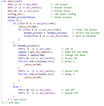
This week I worked on probing actuators in the ATTINY44A C++ Native over Atmel Studio, I add an output device to a microcontroller board you’ve designed, and program it to do something
1. Digital Actuator
The schematic has the principal part to work with sensor an actuator:
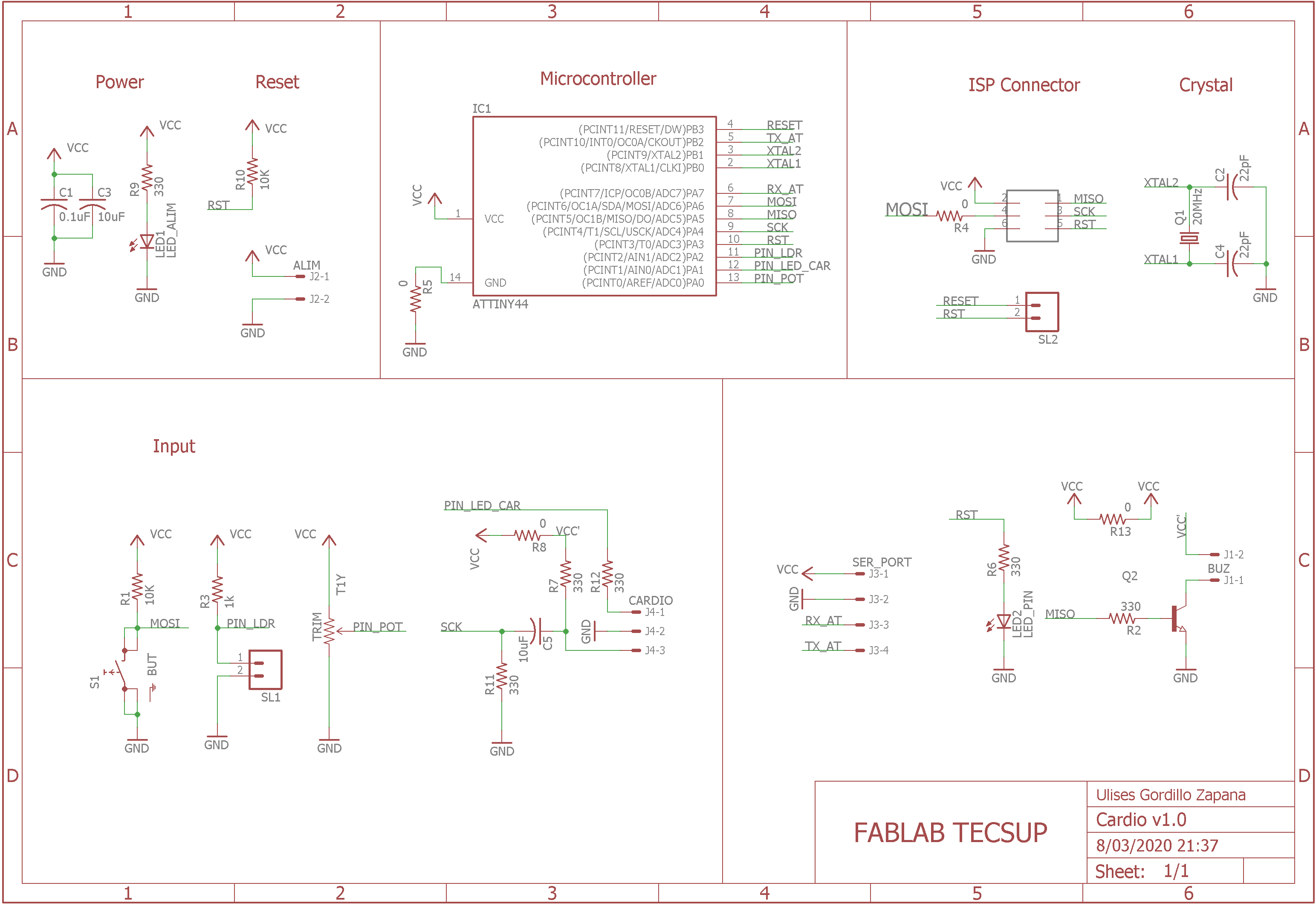
We choose to work with the LED OUTPUT and the BUZZER OUTPUT, and we need a sensor as LDR and BUTTON:

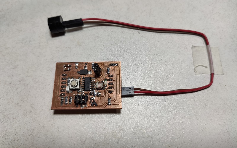
This board was fabricated in WEEK 7: Electronics Design:
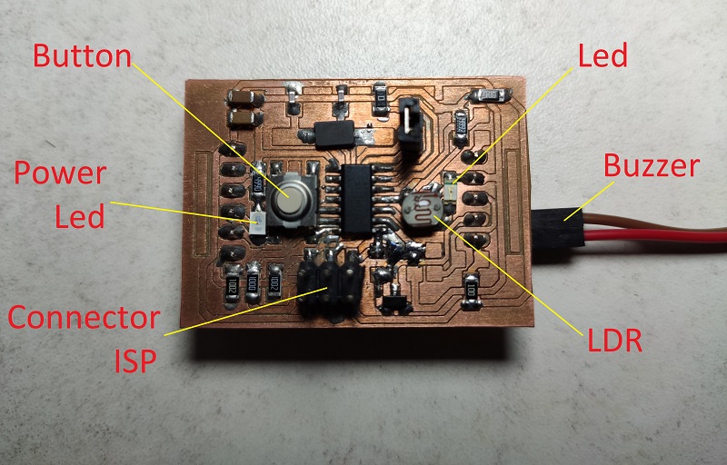
We can see the Sensors and Actuators:
- Buzzer in PIN PA1
- LDR in PIN PA2
- LED in PIN PA3
- Button in PIN PA6
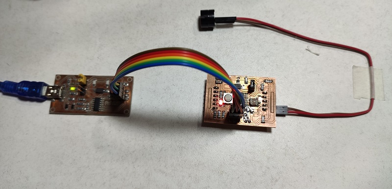
We can see connect to USBTinyISP this board was fabricated in WEEK 7: Electronics Production:
Now we program with the program which:
- The button turn ON or OFF the proccess to control the Sound of Buzzer
- The LDR signal control the frecuency to Buzzer, faster when the light is greater, and slowest when the light is less
2. Project with IR Sensor, DC Motor and Attiny44
For this project shows the operation of opening a door, use a button to start closing or opening, use an infrared sensor to stop the door as a limit switch, and use a motor to move the door.
For this purpose we have the following program:
//****************************************************
// Ulises Gordillo Zapana - FabAcademy 2020
//****************************************************
#define pin_ir      8
#define pin_rly     7
#define pin_but     6
#define pin_buz     4

bool estado_puerta, estado_sistema;

// Function SETUP
void setup() {
  pinMode(pin_ir,INPUT);
  pinMode(pin_rly,OUTPUT);
  pinMode(pin_buz,OUTPUT);
  digitalWrite(pin_buz,HIGH);
}

// Function LOOP
void loop(){
  if (!digitalRead(pin_but)){
    delay(100);
    if (!digitalRead(pin_but)){
      estado_puerta=!estado_puerta;
      estado_sistema=true;
    }
  }
  if (estado_sistema){
    digitalWrite(pin_rly,HIGH);
    while (digitalRead(pin_ir));
    digitalWrite(pin_rly,LOW);
    digitalWrite(pin_buz,LOW);
    delay(500);
    digitalWrite(pin_buz,HIGH);
    estado_sistema = false;
  }
}
We can see how it works in the following video:
GROUP ASSIGNMENT
1. Measuring the Power Consumption
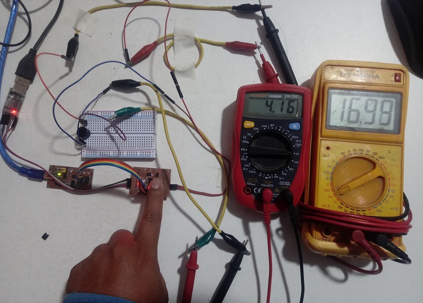
- Measure the power consumption of an output device, in my case I measured the energy consumed from a buzzer that works at 5 volts
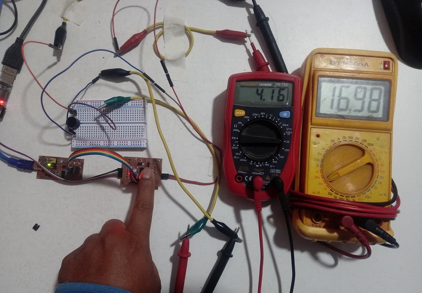
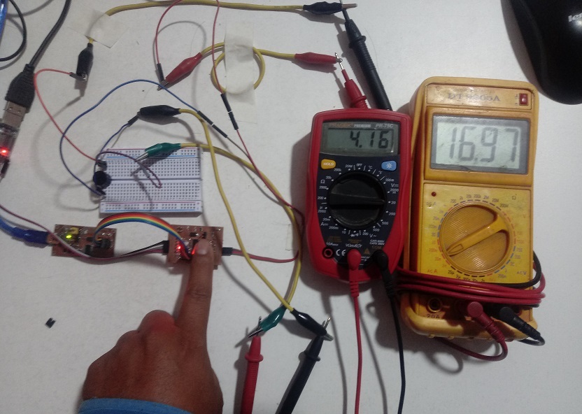
In the image I have the actuator voltage measured on the red multimeter and the current intensity on the yellow multimeter.
- Voltage: 4.16V
- Current: 16.99mA
- Voltage: 4.16V
- Current: 16.98mA
- Voltage: 4.16V
- Current: 16.97mA
In the case of the energy consumed, the watts consumed will be obtained, which would be established by Watt’s Law, which indicates that Power = Voltage x Current Intensity
- P = V x I
| Item | Measuring Current | Measuring Voltage | Power Consumpted |
|---|---|---|---|
| 1 | 16.99mA | 4.16V | 70.6784 mW |
| 2 | 16.98mA | 4.16V | 70.6368 mW |
| 3 | 16.97mA | 4.16V | 70.5952 mW |
2. Probing the Digital Actuator
Designed Files
| Description | Files |
|---|---|
| Door Control Project | Puerta.ino |
| C++ Program | main.cpp |
| Hex Files | Output.hex |