13. Interface and Application Programming
Individual Assignment:
- Write an application that interfaces a user with an input &/or output device that you made
Group Assignment:
- Compare as many tool options as possible
This week I worked on prepare Python to Interface and the schematic to simulation to act the commands.
INDIVIDUAL ASSIGNMENT
Install Python
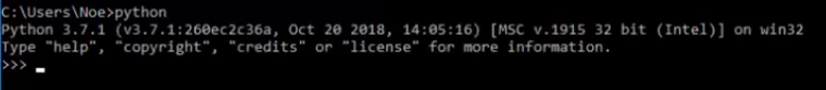
Download python of Oficial page and install, the first check that, the check ADD PYTHON 3.7 PATH.

After you choose NEXT until finish.

You can chech un Prompt Windows when you write python and you see it:
Install Libraries
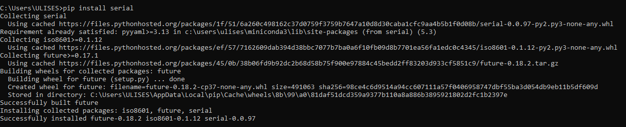
Install the library to communicate with serial board or interface, the standard protocol is UART, it is common in arduino, raspberry and all microcontrollers.
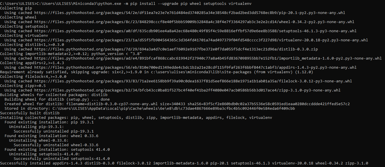
Update the python and the dependencies:
Install the libraries to interface is KIVY, first create the virtual enviroment:


Install the dependencies to KIVY library
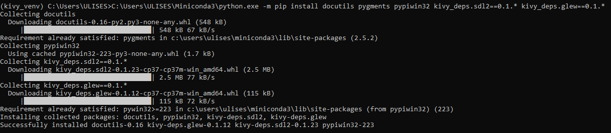

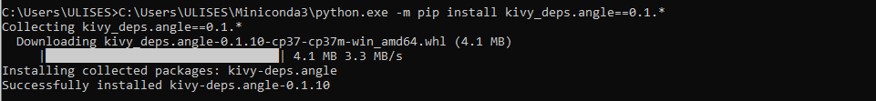
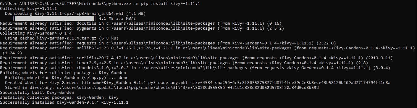
Install the KIVY library
Install the Examples to KIVY

Interface with Attiny44
Programming in Python
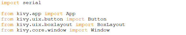
First we include the libraries to use
Then we define the objects in our interface, in our case we will have 4 buttons, 2 to turn on and off a led and 2 to turn on and off a buzzer
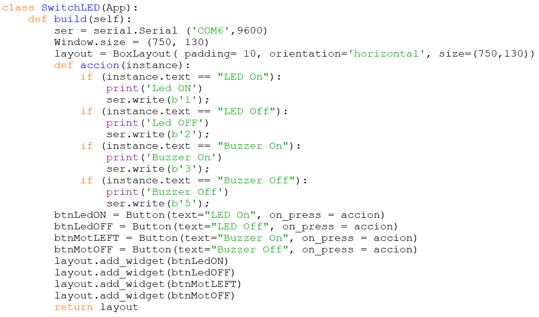
The program link some letters with commands to board, it is the following:
| Action | Commands |
|---|---|
| Led ON | char ‘1’ |
| Led OFF | char ‘2’ |
| Buzzer On | char ‘3’ |
| Buzzer Off | char ‘5’ |
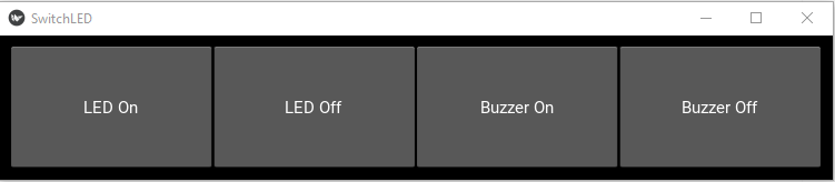
Finally we build the interface
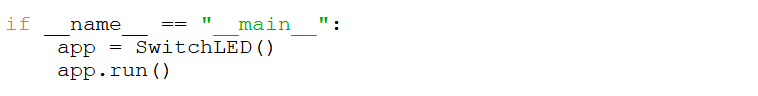
When we run the module, it looks:
Programming in Attiny44 with Arduino IDE
The writed program is the following:
//****************************************************
// Ulises Gordillo Zapana - FabAcademy 2020
//****************************************************
#define pin_tx      8
#define pin_rx      7
#define pin_but     6
#define pin_buz     5
#define pin_cardio  4
#define pin_led     3
#define pin_ldr     A2
#define pin_led_car 1
#define pin_pot     0

// Include Resource
#include <SoftwareSerial.h>
SoftwareSerial SerialPort(pin_rx, pin_tx); // RX, TX
byte dato;
long time_prev,time_now,time_req;
// Function SETUP
void setup() {
  SerialPort.begin(9600);
  pinMode(pin_but,INPUT);
  pinMode(pin_buz,OUTPUT);
  pinMode(pin_cardio,OUTPUT);
  digitalWrite(pin_cardio,HIGH);
  pinMode(pin_led,OUTPUT);
  pinMode(pin_led_car,OUTPUT);
}

// Function LOOP
void loop(){
  if (SerialPort.available()){
    dato = SerialPort.read();
    switch(dato){
      case '1':
        digitalWrite(pin_led,HIGH);
      break;
      case '2':
        digitalWrite(pin_led,LOW);
      break;
      case '3':
        digitalWrite(pin_cardio,LOW);
      break;
      case '4':
        digitalWrite(pin_cardio,LOW);
      break;
      case '5':
        digitalWrite(pin_cardio,HIGH);
      break;
    }
  }
}
Electronic Board
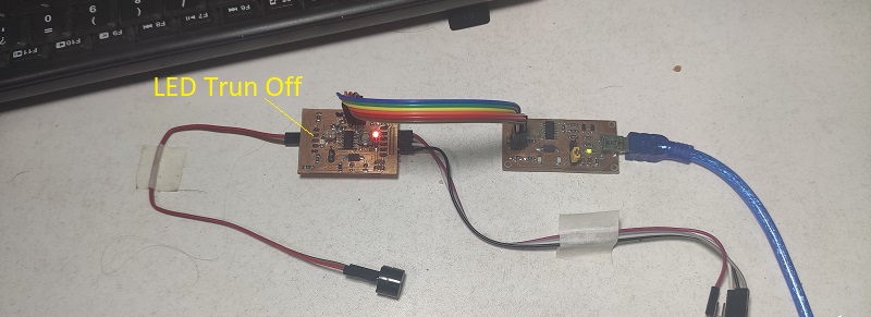
The board is the following, it is designing and fabricate in Week 7: Electronics Desing, Week 10: Input Device and Week 12: Output Devices:
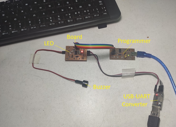
Testing
The test is with LED in images, and the buzzer we can see en the next video in Video Demostration:
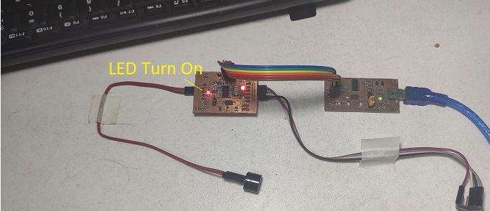
- Turn On the LED
- Turn Off the LED
Video Demonstration
It is the demostration:
GROUP ASSIGNMENT
Interface with Simulation of Arduino Uno
First we include the libraries to use
Then we define the objects in our interface, in our case we will have 5 buttons, 2 to turn on and off a led and 3 to turn left, turn right and turn off a DC motor:
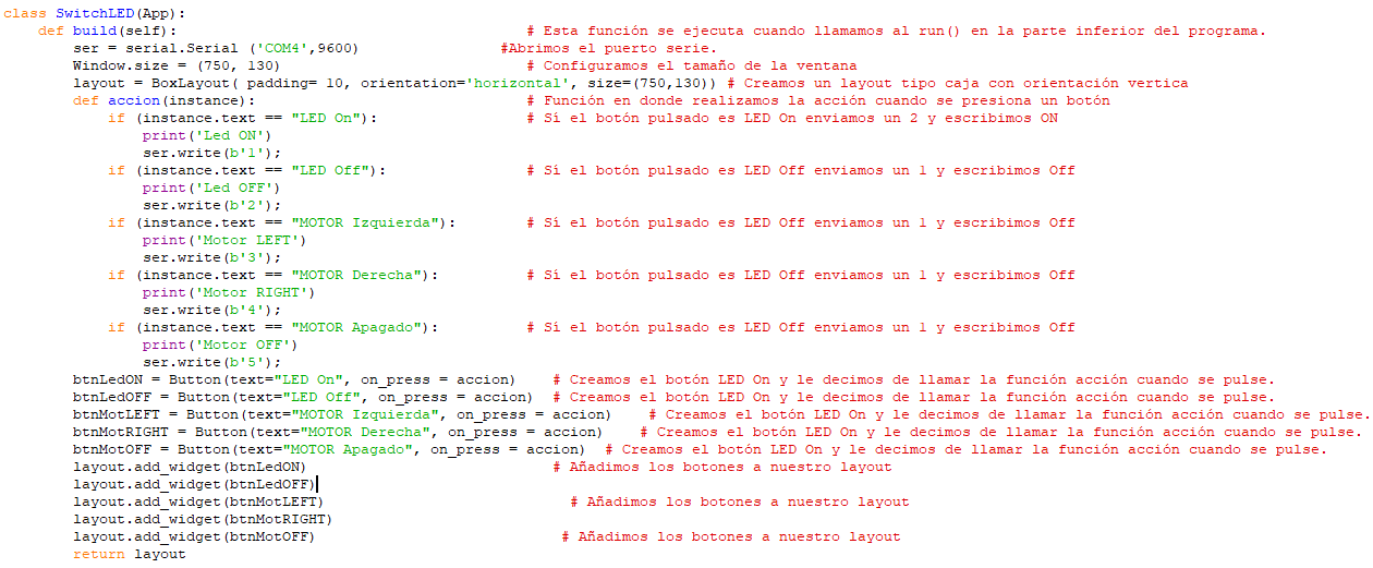
The program link some letters with commands to board, it is the following:
| Action | Commands |
|---|---|
| Led ON | char ‘1’ |
| Led OFF | char ‘2’ |
| Motor LEFT | char ‘3’ |
| Motor RIGHT | char ‘4’ |
| Motor OFF | char ‘5’ |
And the command to run the app

Programming in ARDUINO UNO with Arduino IDE
The writed program is the following:
void setup() {
  // put your setup code here, to run once:
  pinMode(5,OUTPUT);
  pinMode(6,OUTPUT);
  pinMode(7,OUTPUT);
  Serial.begin(9600);
}

void loop() {
  // put your main code here, to run repeatedly:
  if (Serial.available()){
    switch(Serial.read()){
      case '1':
        digitalWrite(7,HIGH);
      break;
      case '2':
        digitalWrite(7,LOW);
      break;
      case '3':
        digitalWrite(5,HIGH);
      break;
      case '4':
        digitalWrite(5,LOW);
      break;
      case '5':
        digitalWrite(6,HIGH);
      break;
      case '6':
        digitalWrite(6,LOW);
      break;
    }
  }
}
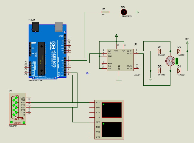
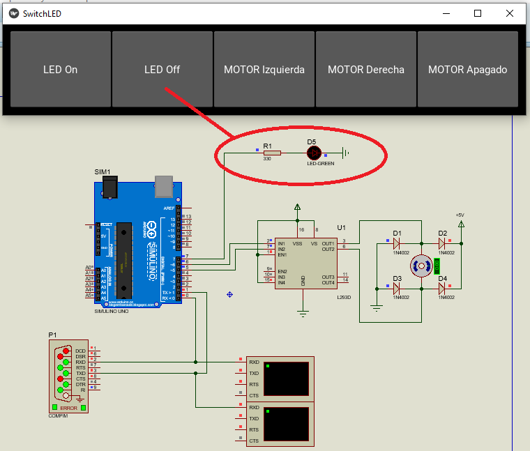
Design the schematic
In the schematic, there are a led, a motor and the UART port, this schematic is workimg in Proteus Software.
Simulate the Interface
When I click on the ‘LED On’ button in simulator the LED Turn ON:
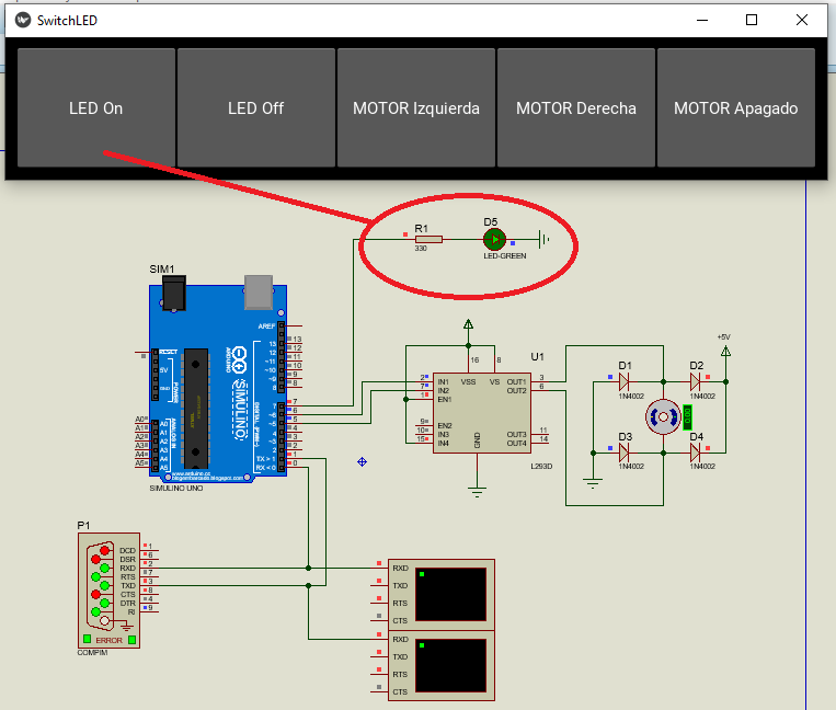
When I click on the ‘LED Off’ button in simulator the LED Turn OFF:
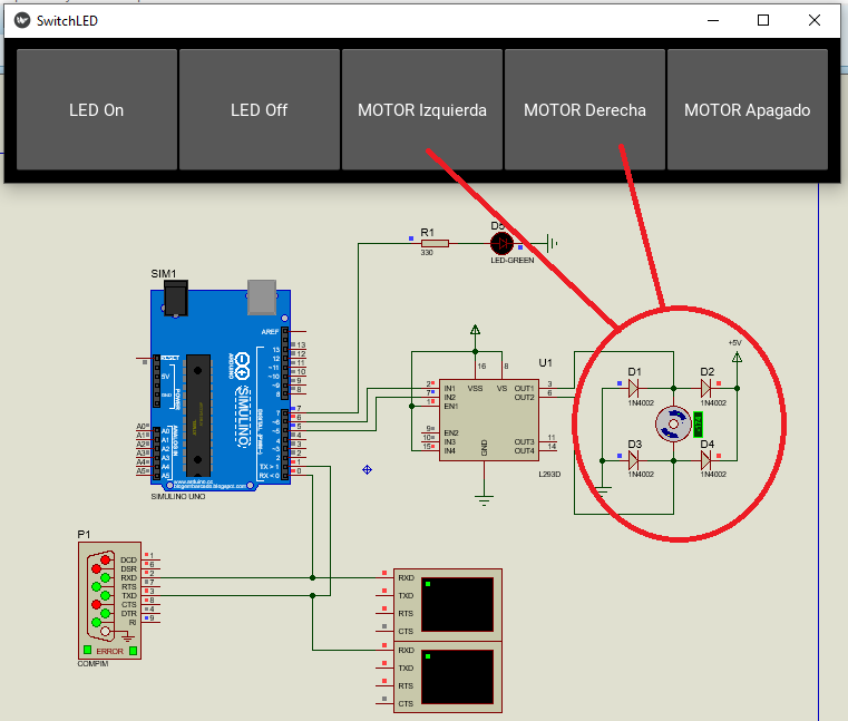
When I click on the ‘MOTOR Izquierda’ button or ‘MOTOR Derecha’ button in simulator the MOTOR turn Left or Right:
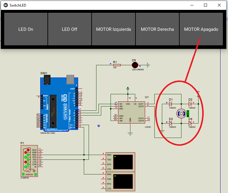
Finally when I click on the ‘MOTOR APAGADO’ the MOTOR Turn OFF:
Video Simulation
COMPARISON
In my case, I did using python and the microntrollers were different: the Attiny44 and the Arduino Uno, which is designed with an Atmega328P.
The response was similar, since in both cases I used the serial position to communicate.
In the case the Attiny44 does not have a serial port that is why I had to use a serial port created by software with the SoftwareSerial library in Arduino IDE
We can see a table of comparison:
| Item | Feature | Attiny44 | Arduino Uno |
|---|---|---|---|
| 1 | Memory | 4kB | 32kB |
| 2 | Pins | 14 | 28 |
| 3 | Serial Port | No | Yes |
| 3 | Crystal | 20Mhz | 16Mhz |
Designed Files
| Description | Files |
|---|---|
| Interface of Python to Attiny44 | Interface_Attiny44.py |
| Program Attiny44 | SoftSerial.ino |
| Interface of Python to Arduino | Interface_python.py |
| Program Arduino | Arduino_Interface.ino |
| Schematic on Proteus | Simulacion_Arduino.pdsprj |