3. Computer Aided design
Assignment
- Model (raster, vector, 2D, 3D, render, animate, simulate, …) a possible final project, compress your images and videos, and post it on your class page
In this page we will explain how the design of different tools on 3D and 2D designs because I will need it to work in the laboratory.
Also I will work with the final project’s design.
Final Project Advance
3D Design
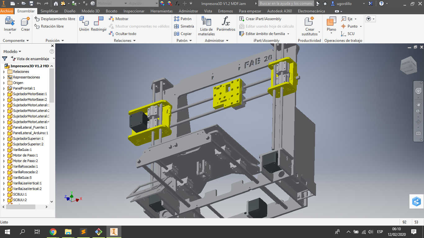
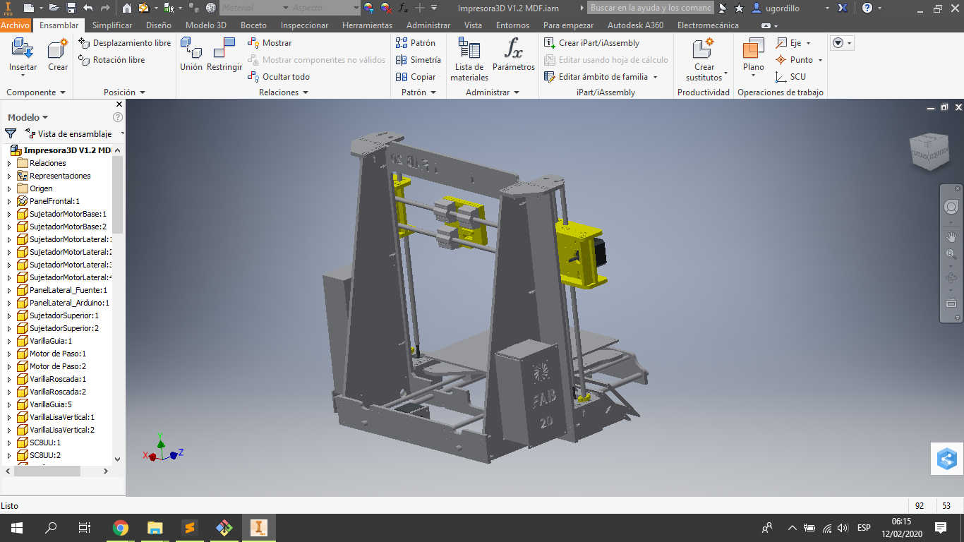
In this advance, the work is design the frame, the move axis, this show is the assembly of the parts, the parts are design in Autodesk Inventor.
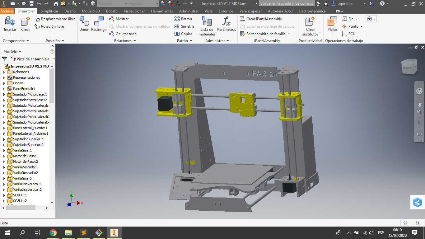
It is a 3D printer structure with all the part in 2D parts.
The Design files are in FINAL PROJECT page
Image Software: Gimp
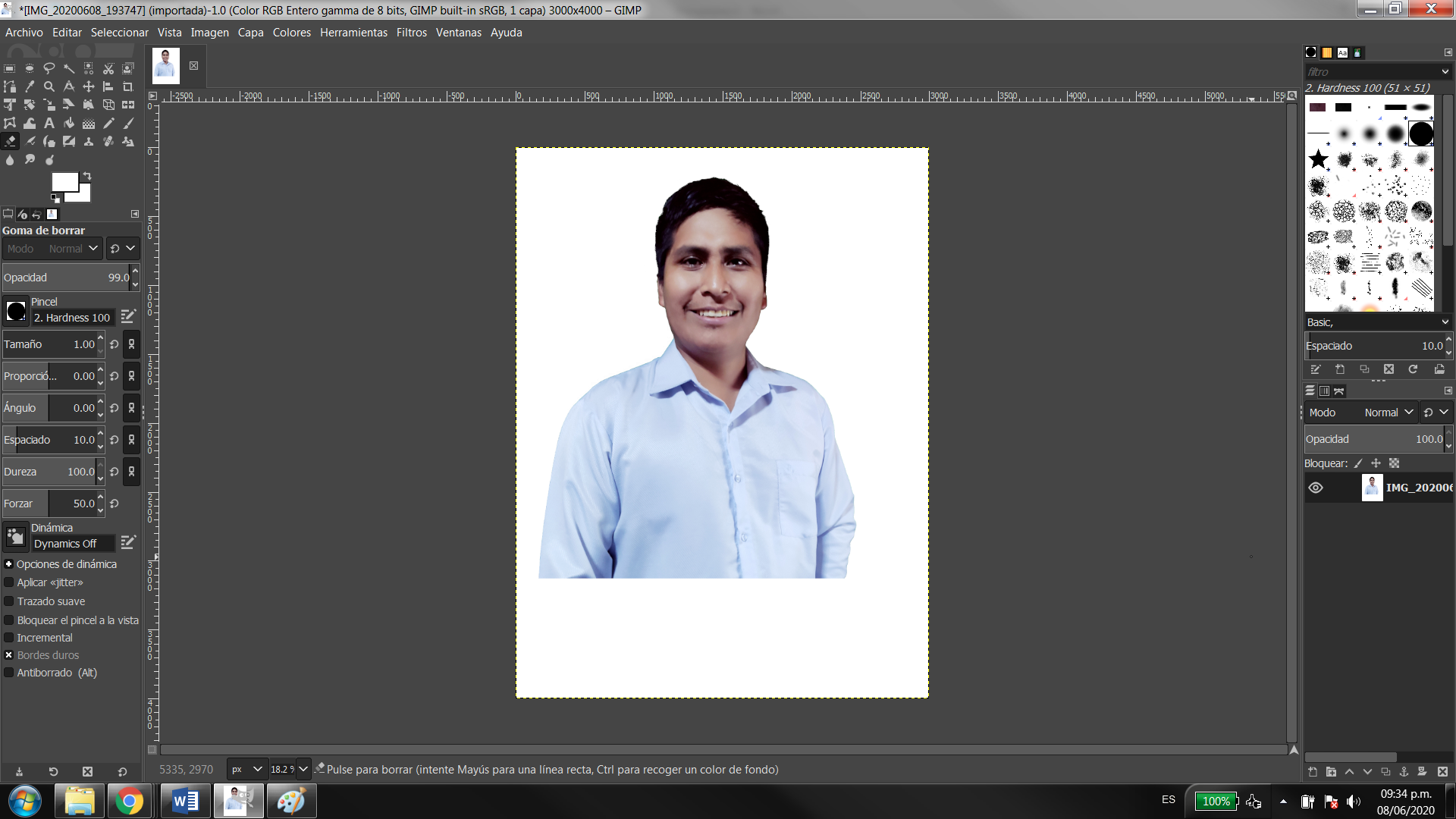
This software is a tool to edit image, pixel to pixel, but it has very nice tool as cutter and filters, in this item I use GIMP to erase the background.
Editing Image

- Run the GIMP in the command line, in my case I have the GIMP 2.1012
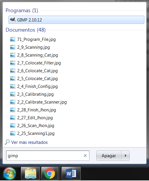
- Displays the home screen with the logo
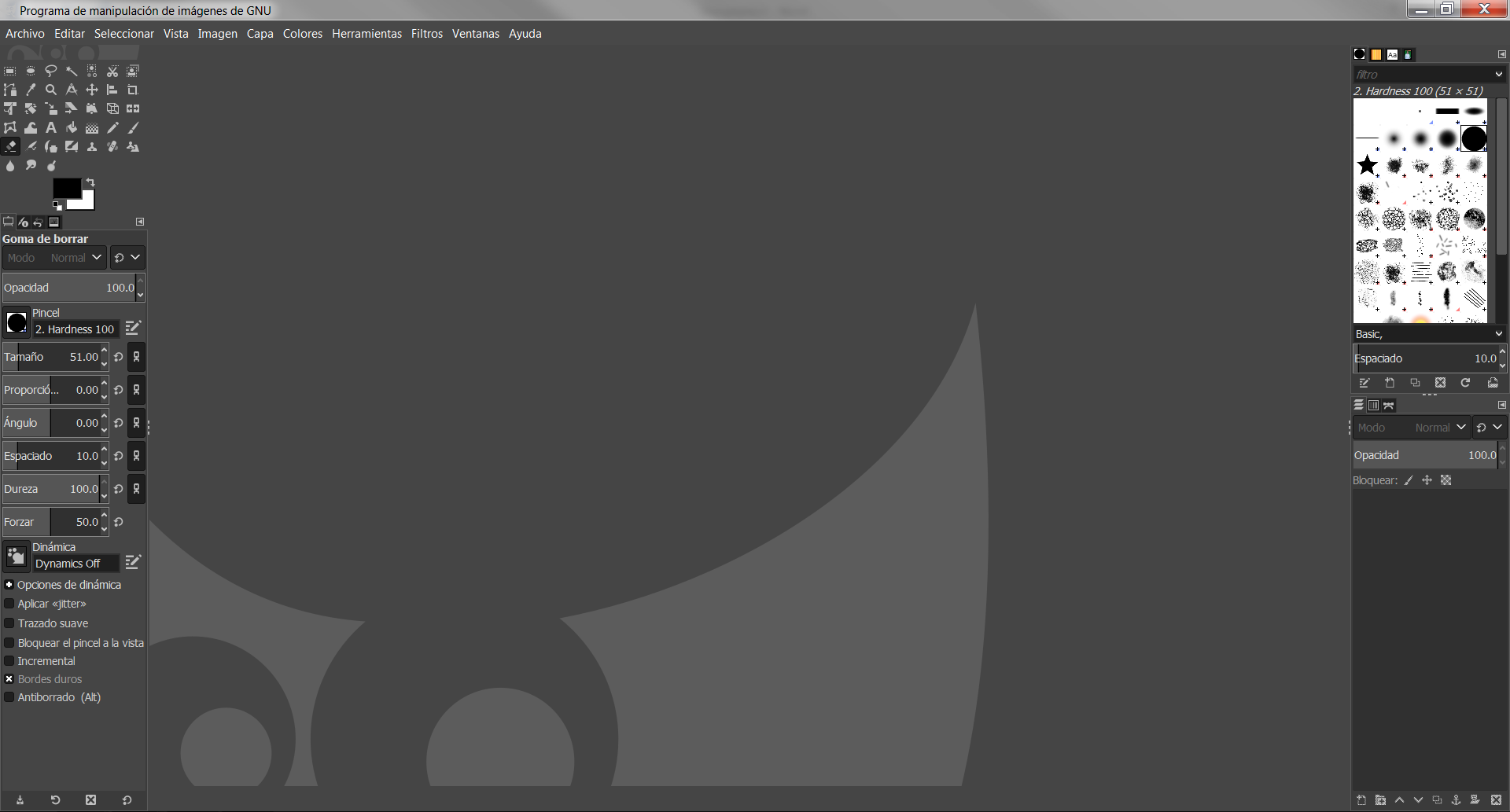
- The GIMP appearance is the following, when I can access to the diferents processing image tool
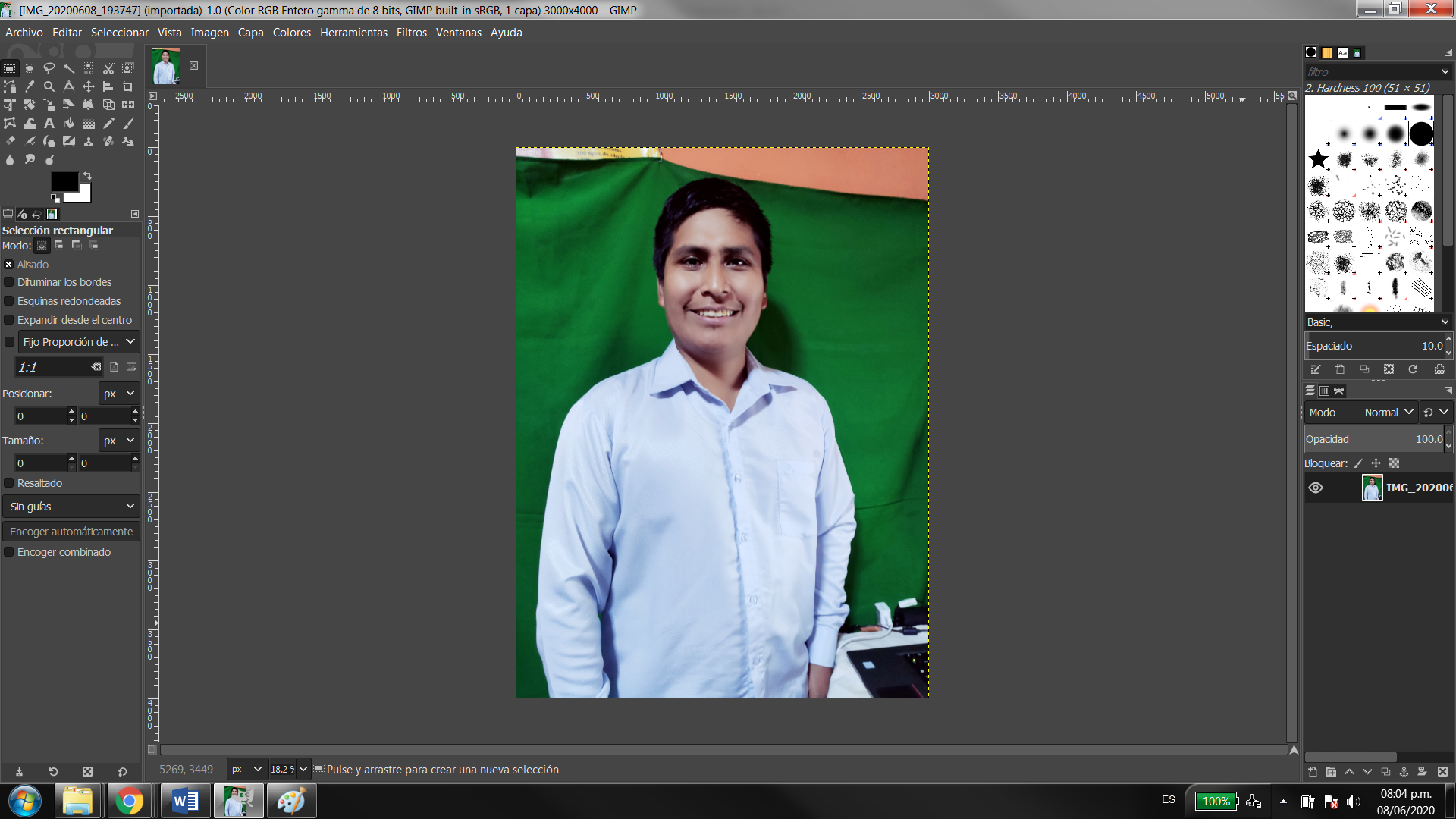
- I took the photo with a cell phone and open the file in GIMP:
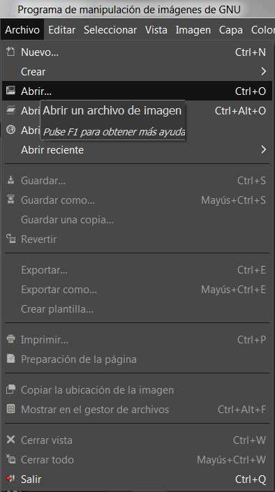
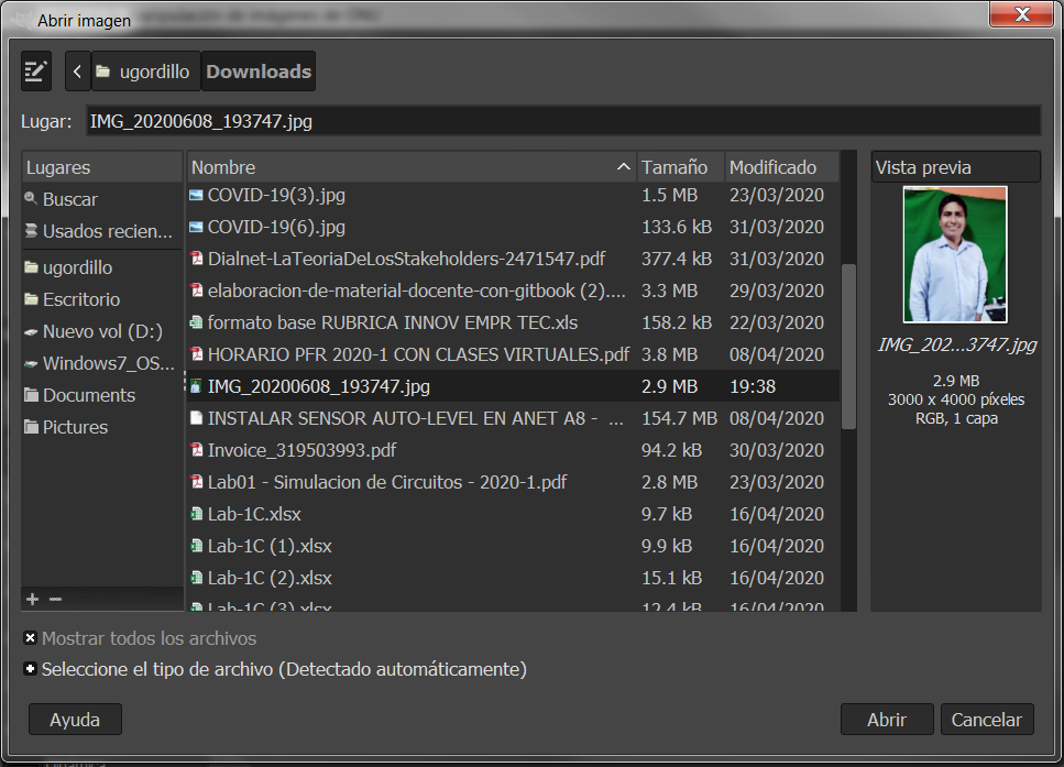
- I choose the file in my windows explorer:
- When the image is loaded, I can start processing the image:
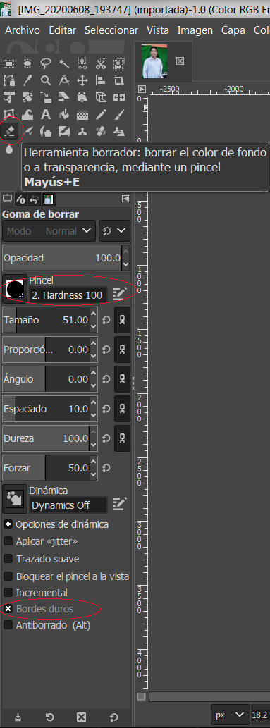
- I choose the ERASER TOOL,I change the pincel to HARDNESS 100 and I check the HARD EDGES because it help me work quickly
- I start the erasing process on the outline of the person
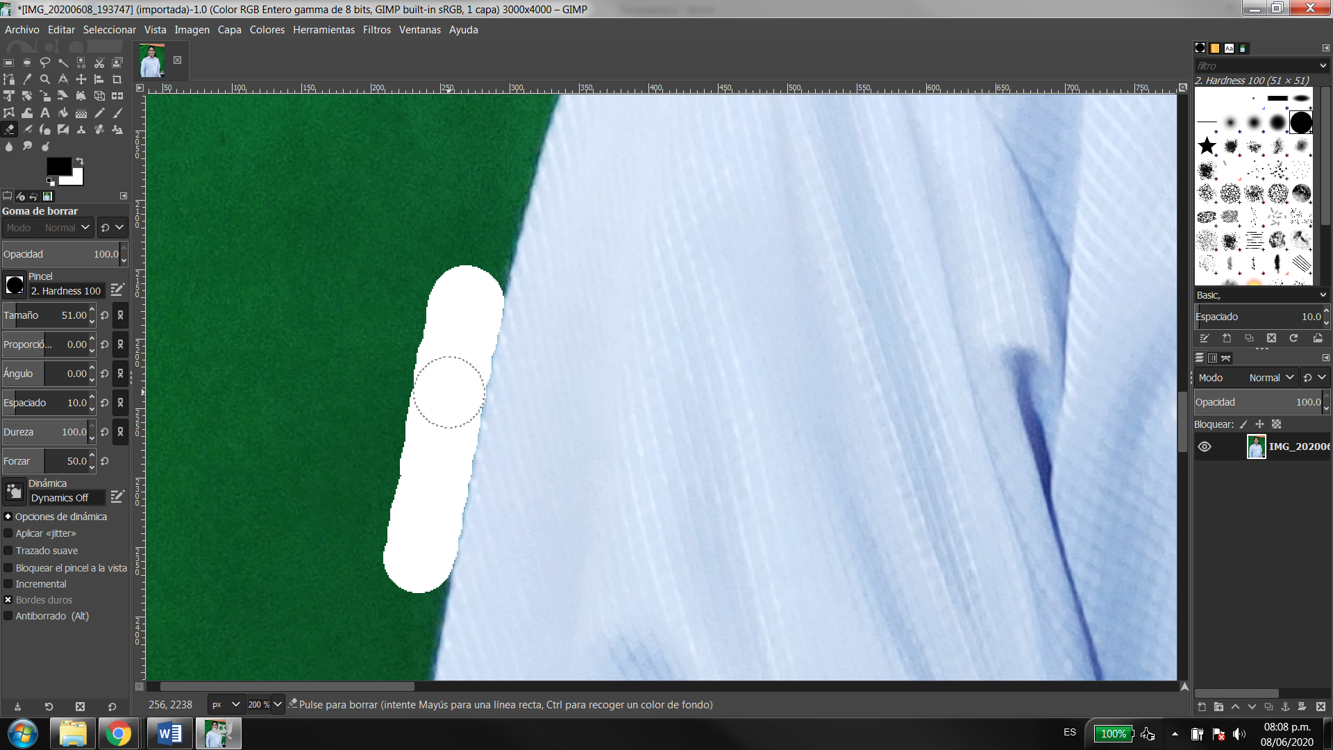
- I can erase large areas to advance faster
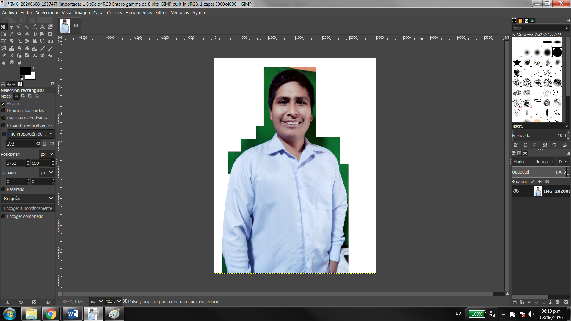
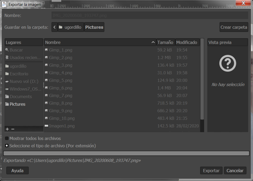
- Afterwards, I have only the person image, and it is ready to save:
- I save the image with other name
- It looks so good, I erased the background

- This is a comparison between the captured image and the processed image

Video Software: Filmora
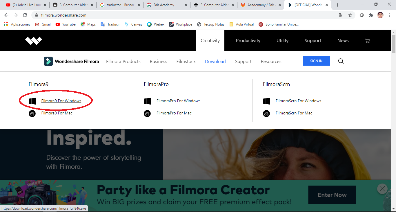
Download the install’s file of official page https://filmora.wondershare.com/ to windows choose the Filmora 9 For Windows file.
Installing Filmora
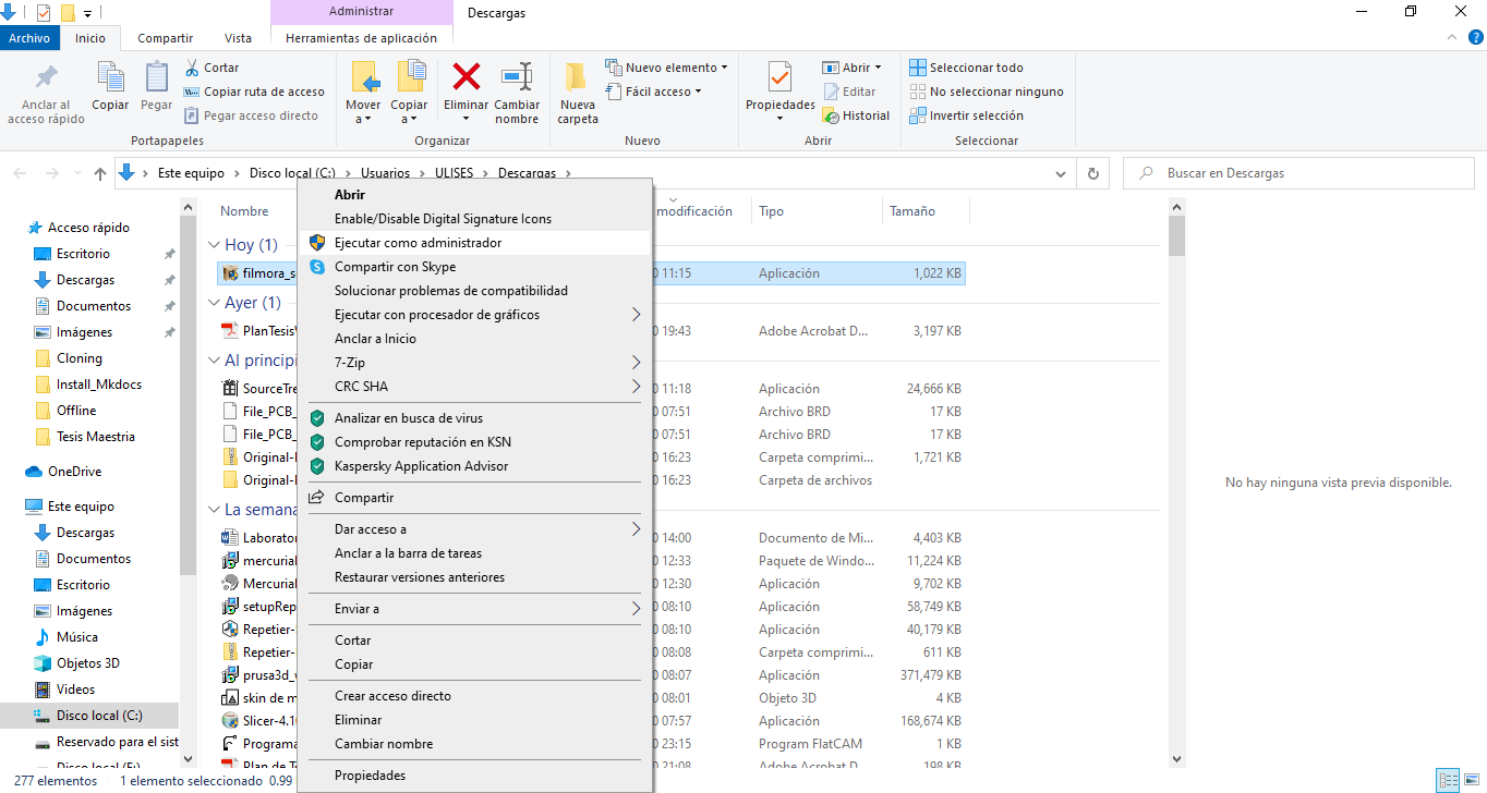
- I download the installer file:
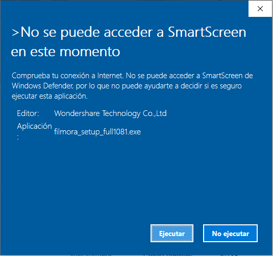
- I execute the installer file as administrator:
- The windows require prermission to install the software, click in Execute
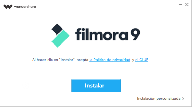
- So appear some windows to installation, I press INSTALL or NEXT:
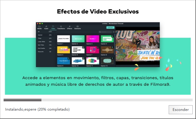
- So the proccess of install is running:
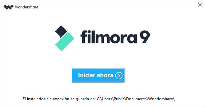
- And finally the installation is finished now I run the FILMORA9
Editing Video File
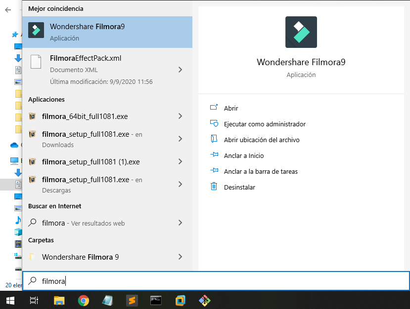
- Search the FILMORA9 in command line of windows:
- The software load the dependies and libraries for first time:

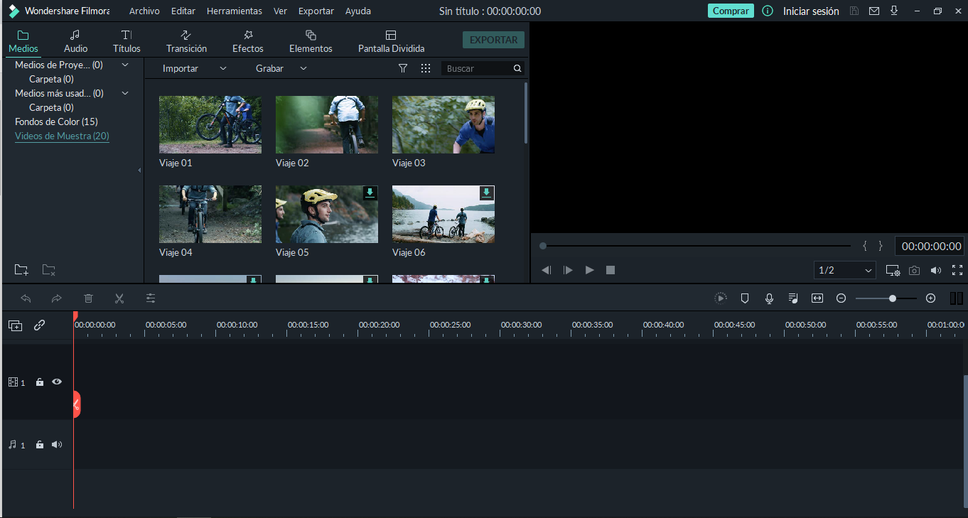
- I can see the interface’s FILMORA:
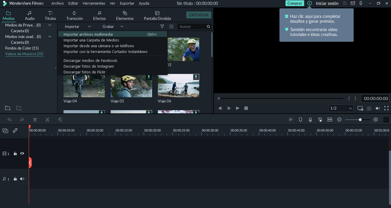
- First, I import a video file, it is a video that explain my website, I click in IMPORT button and choose Import multimedia file option:
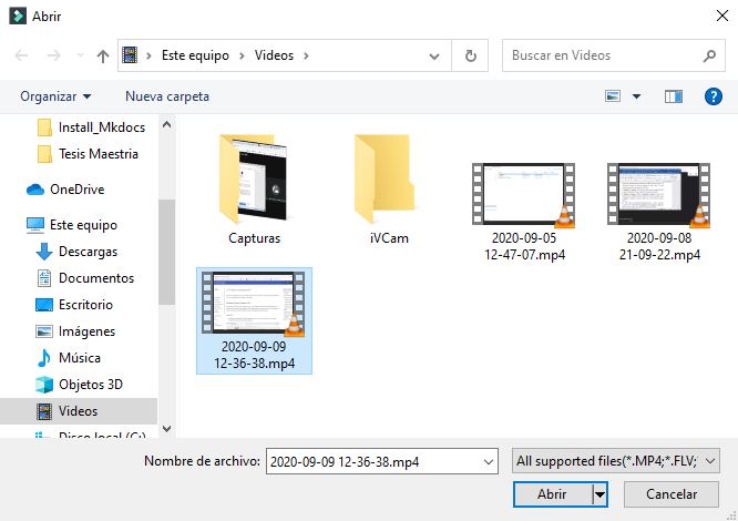
- I search the video file, select and pres the OPEN button:
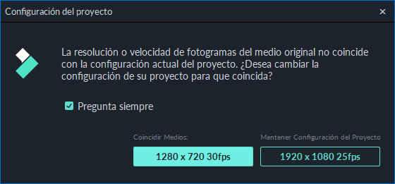
- So the software require the size to design, I choose HD video that is 1280x720 30fps button:
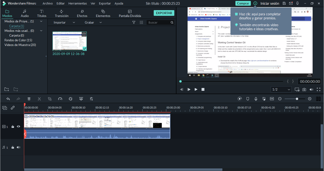
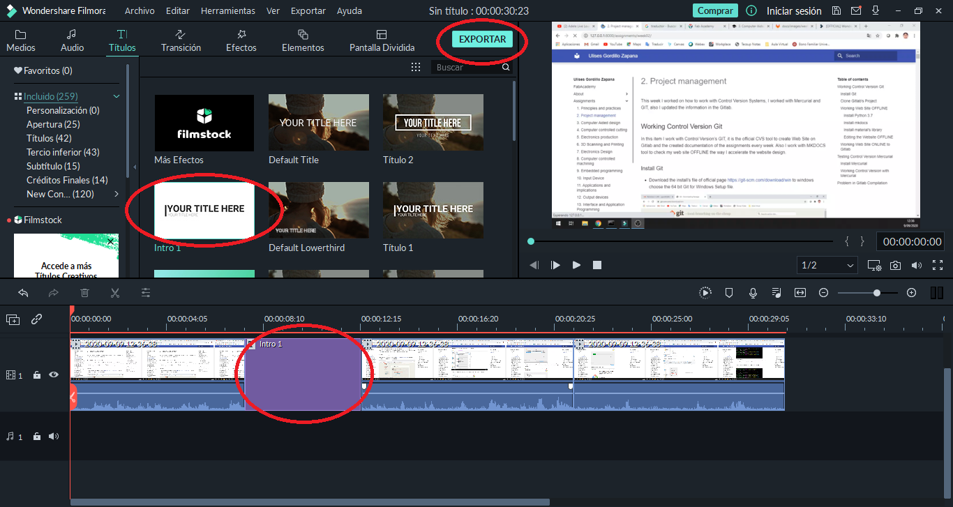
- I take the file and drag it onto the timeline in the lower area and the file can be edited
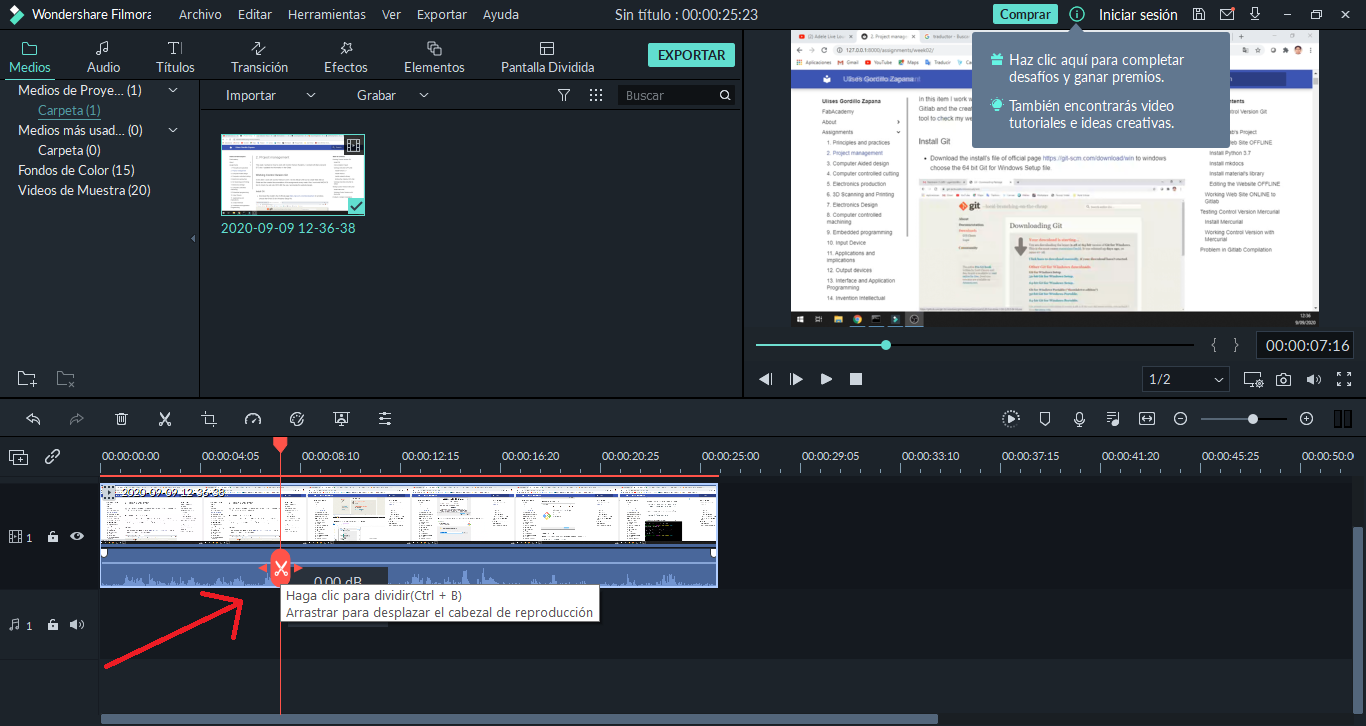
- A tool that I will always need is to cut, this has the appearance of a scissor, I place in the time where I am going to cut and press the image of the scissors
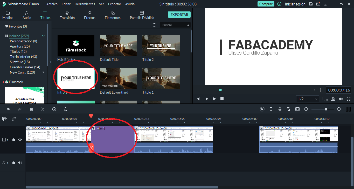
- I can move the cut file and add an image with a title, this can be done with the TITLES option, dragging the title template to the timeline and I change the text of title:
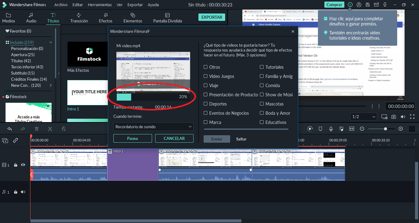
- Afterwards I have designed, I can export the file and save the video file:
- I choose the free option of filmora:
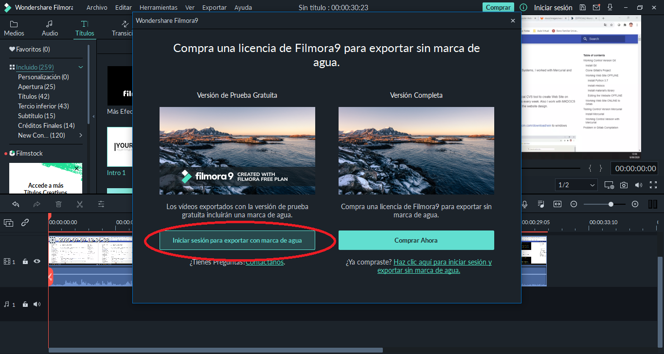
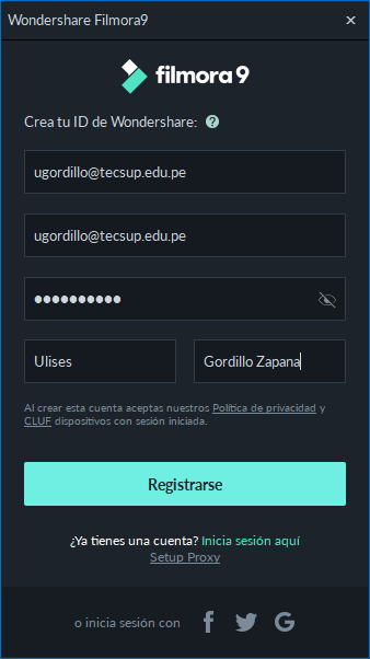
- For free version I must register to Wondershare:
- Afterwards, I can save the file with the prefered size and name:
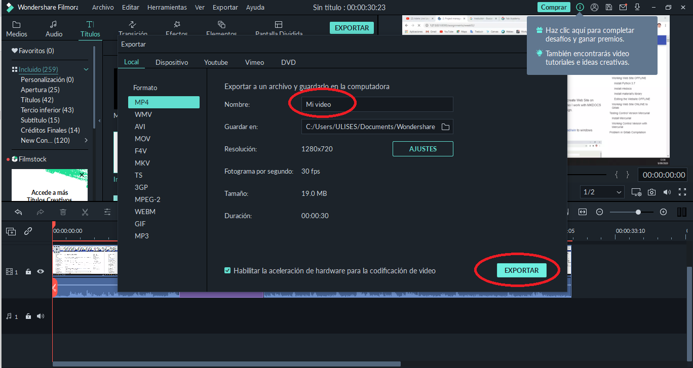
- The proccess to save is running with a progress bar until 100%
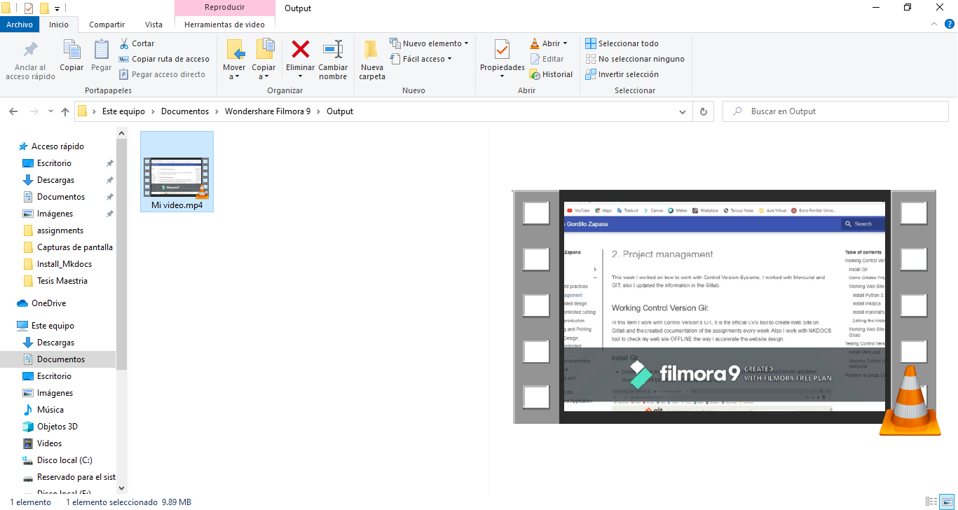
- So I can see the edited file:
2D Software: Corel Draw
When I work with project of robotic or prototypes, I will need to work any 2D software to change some features or configurations after modeling in CAD software, I will use Corel Draw, where I can do this work, but in this software I can design the project from zero too:
Editing PDF to DXF file
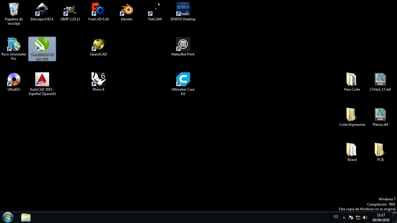
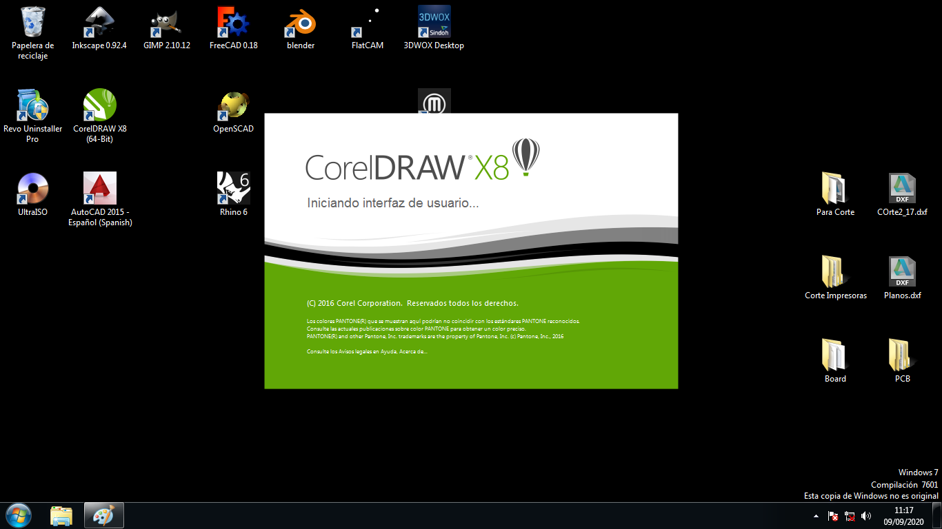
- I execute the software in the Corel Draw icon:
- The program shows the begin window:
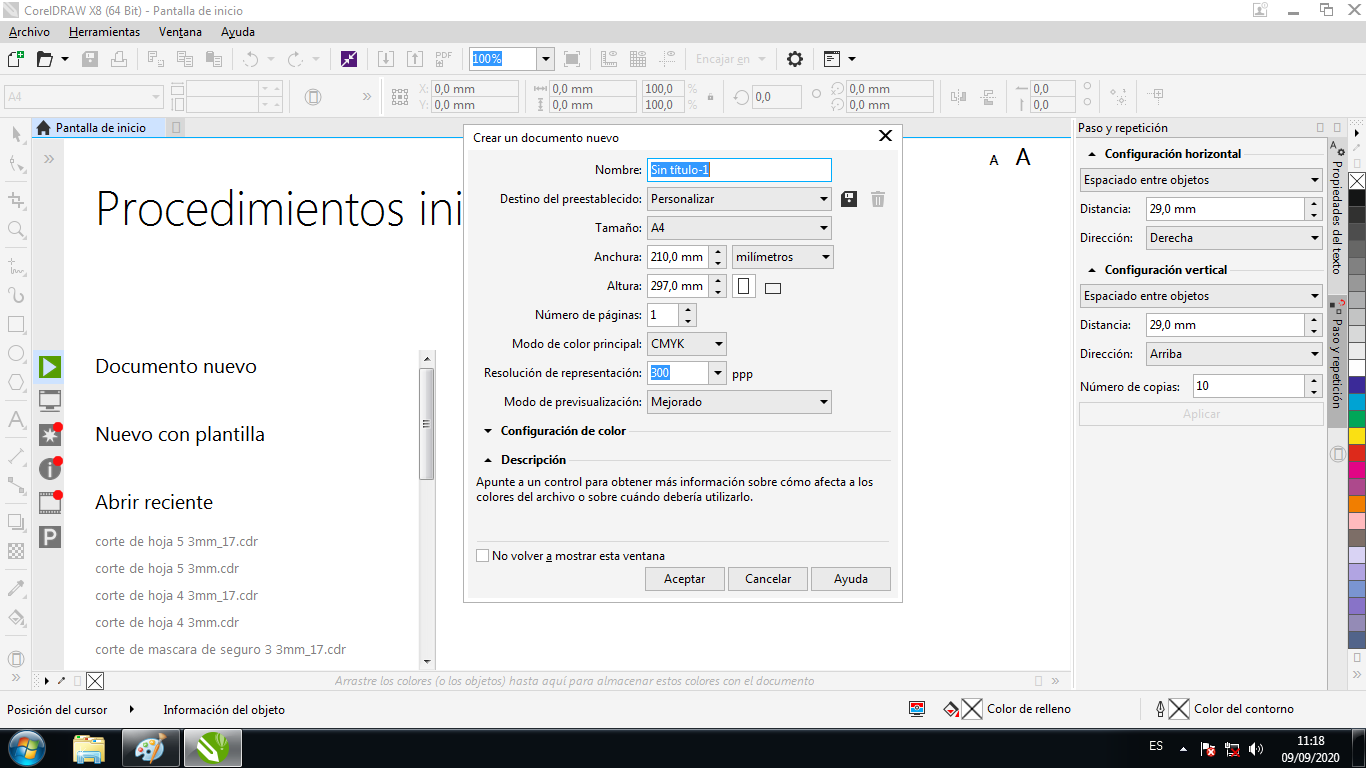
- So I click File -> New, the configuration is the following of the document’s features, and click in ACCEPT button
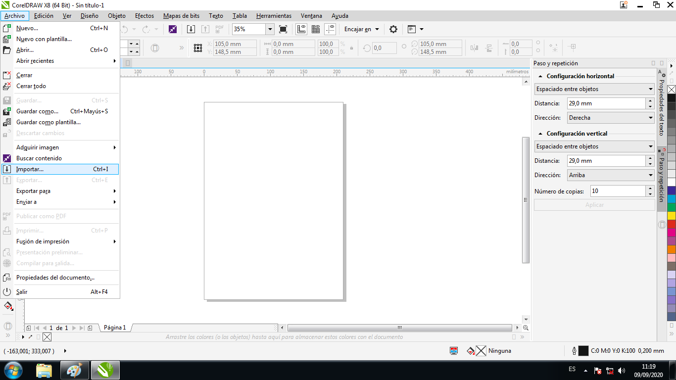
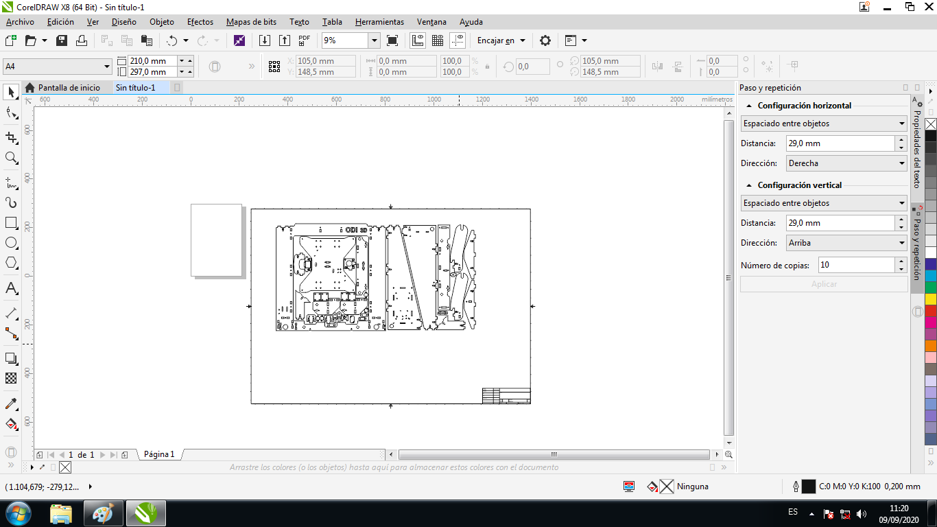
- In my case I import the 2D file create on Inventor, it is a PDF file:
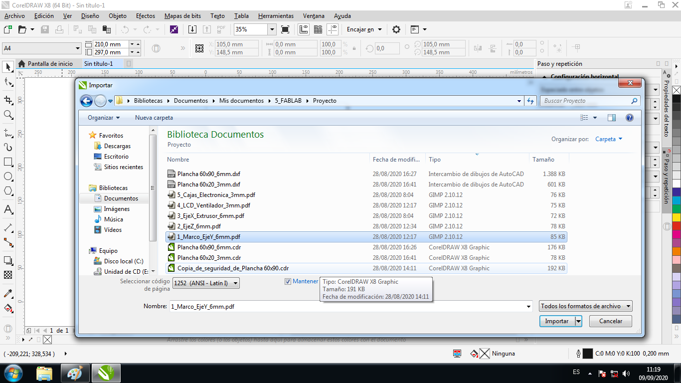
- I choose the PDF file to import:
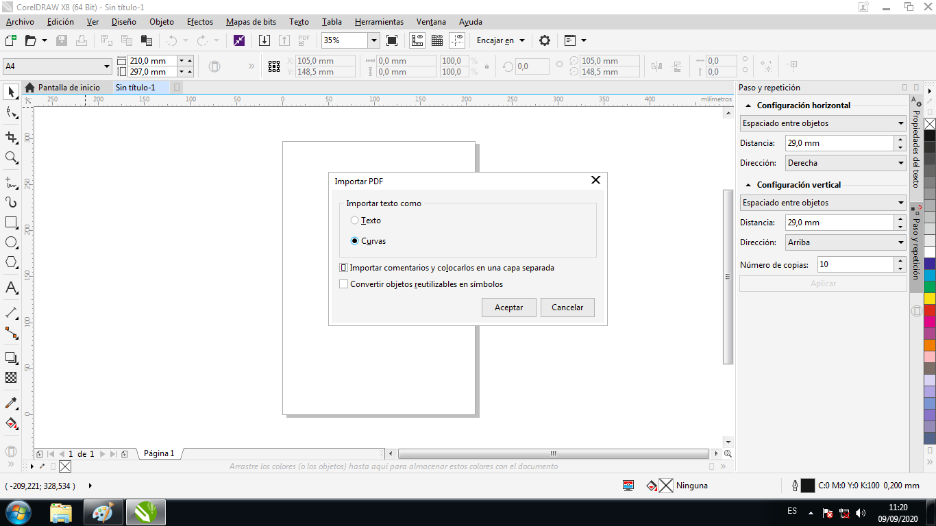
- The Corel Draw require define the type of objects that there are in the file, I choose curve and click in ACCEPT button
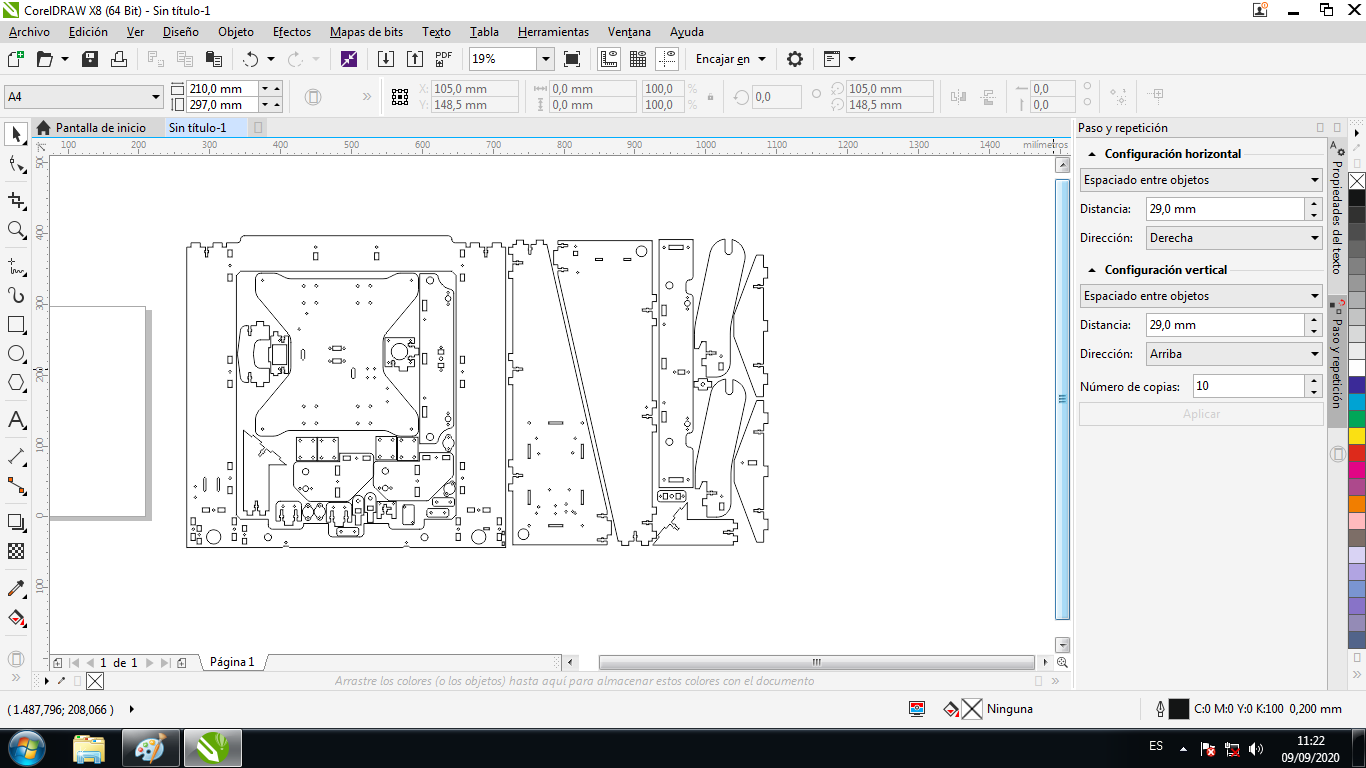
- I place it in any coordinate:
- The design has some parts that I do not require to work, so I delete them with select and the delete key on the keyboard
- I select all the design and change the thickness from line to very fine
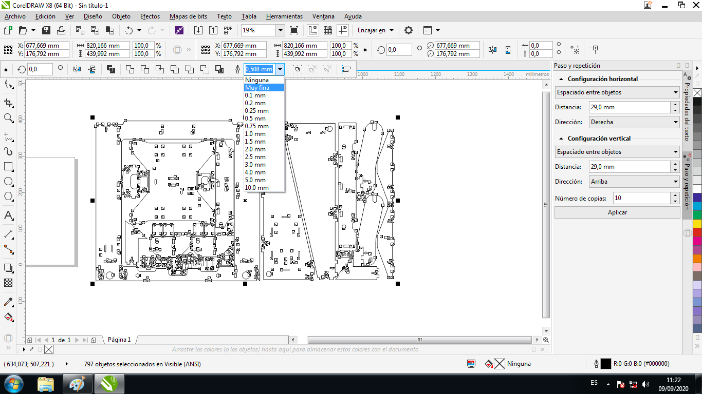
- Now I am ready to export the DXF file to use in digital fabrication
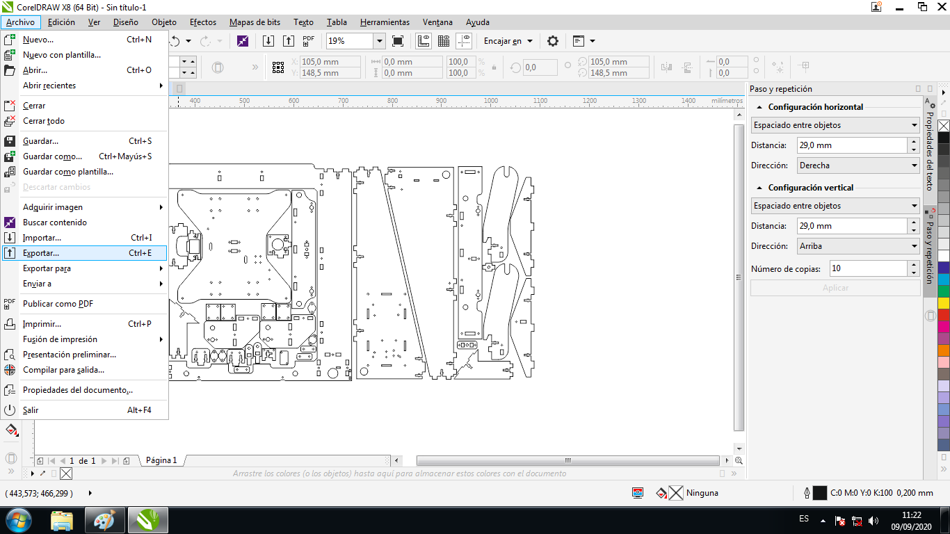
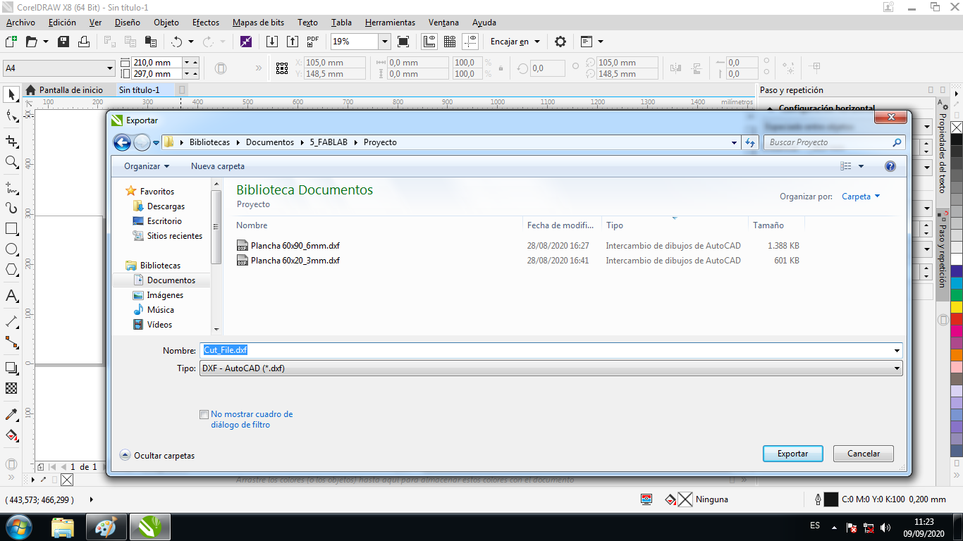
- I put the name to the file and click on the EXPORT button
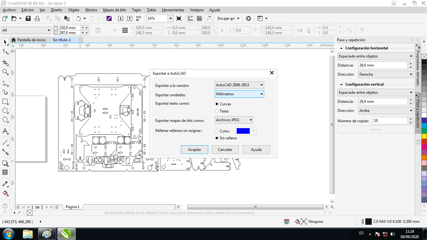
- I configurate the parameters to DXF file and press the ACCEPT button:
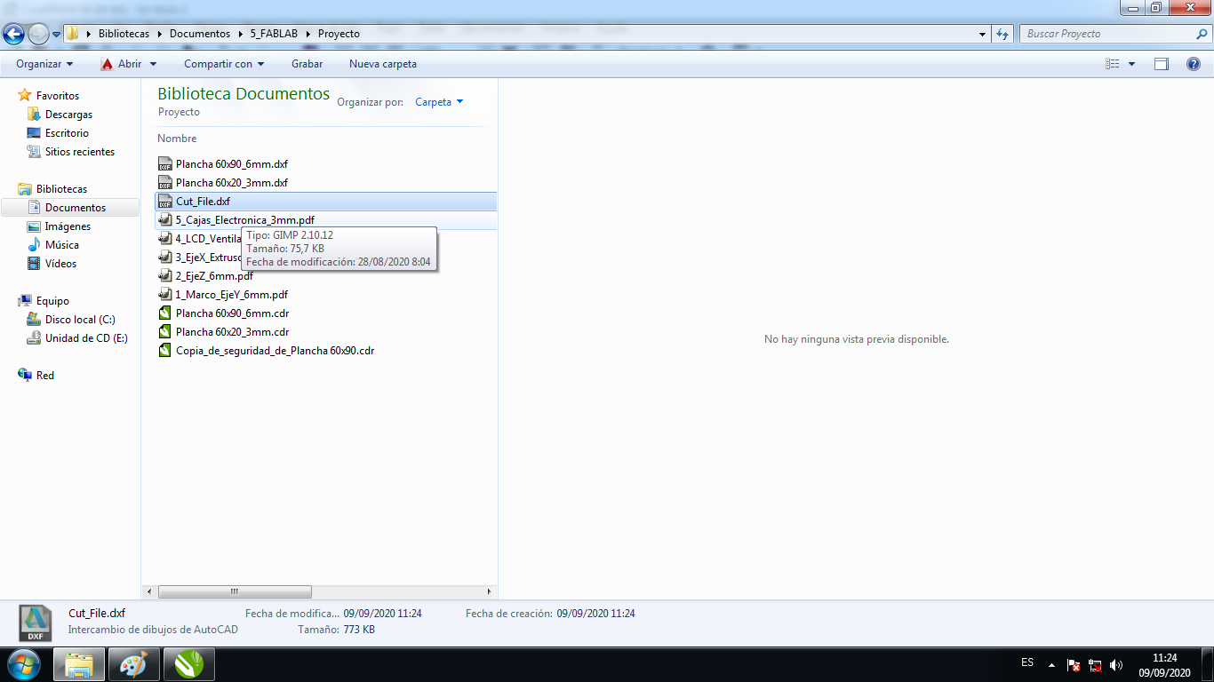
- And finally, I can see the DXF file to work in Digital Fabrication in any machines.
3D Software: Working with Raspberry Project
I am electronic and I need some physical blocks to work with electronic modules such as Raspberry an Arduino. So the projects are modules that we need to manufacture for work with electronic.
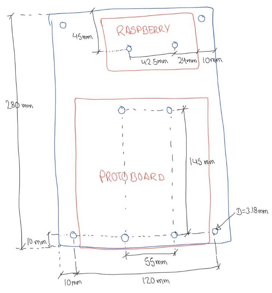
The project is a plataform to install 2 protoboards, a power supply and raspberry board.
Raspberry Project with OPENSCAD
OpenSCAD is a free application to create solid CAD objects. It is not an interactive editor but a 3D compiler based on a textual description language
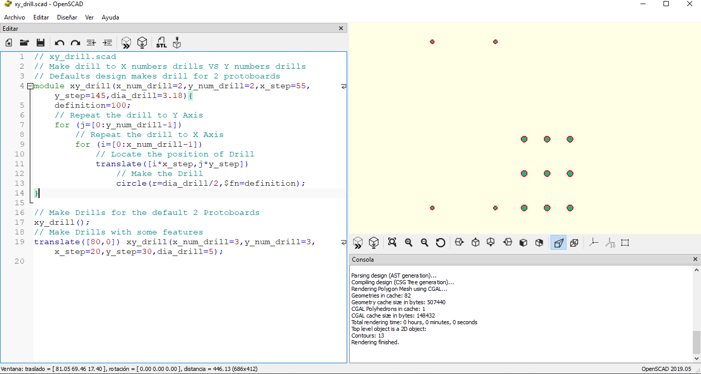
Parametric Library First we design a library to create drill with X number vs Y number. It is the code:
    // xy_drill.scad
    // Make drill to X numbers drills VS Y numbers drills
    // Defaults design makes drill for 2 protoboards
    module xy_drill(x_num_drill=2,y_num_drill=2,x_step=55,y_step=145,dia_drill=3.18){
        definition=100;
        // Repeat the drill to Y Axis
        for (j=[0:y_num_drill-1])
            // Repeat the drill to X Axis
            for (i=[0:x_num_drill-1])
                // Locate the position of Drill
                translate([i*x_step,j*y_step])
                    // Make the Drill
                    circle(r=dia_drill/2,$fn=definition);
    }
This is some examples
    // Make Drills for the default 2 Protoboards
    xy_drill();
    // Make Drills with some features
    translate([80,0]) xy_drill(x_num_drill=3,y_num_drill=3,x_step=20,y_step=30,dia_drill=5);
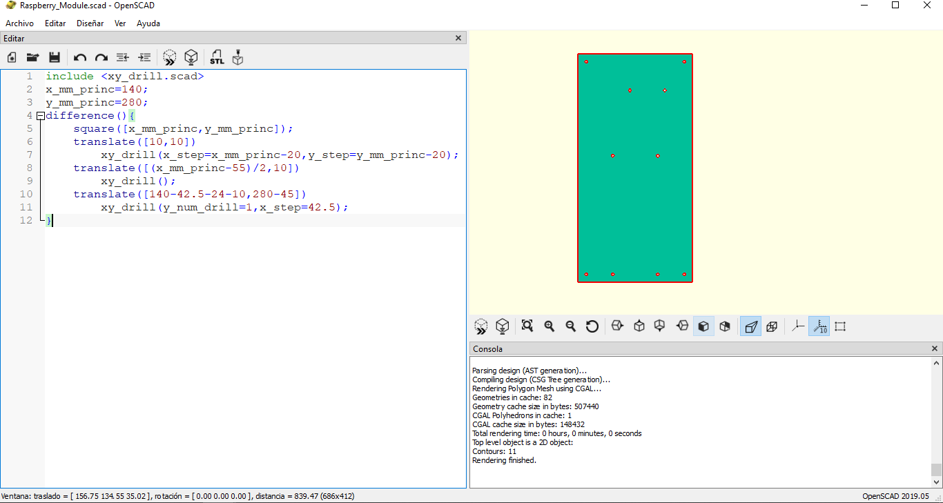
This is the design with OPENSCAD:
includex_mm_princ=140; y_mm_princ=280; difference(){ square([x_mm_princ,y_mm_princ]); translate([10,10]) xy_drill(x_step=x_mm_princ-20,y_step=y_mm_princ-20); translate([(x_mm_princ-55)/2,10]) xy_drill(); translate([140-42.5-24-10,280-45]) xy_drill(y_num_drill=1,x_step=42.5); }
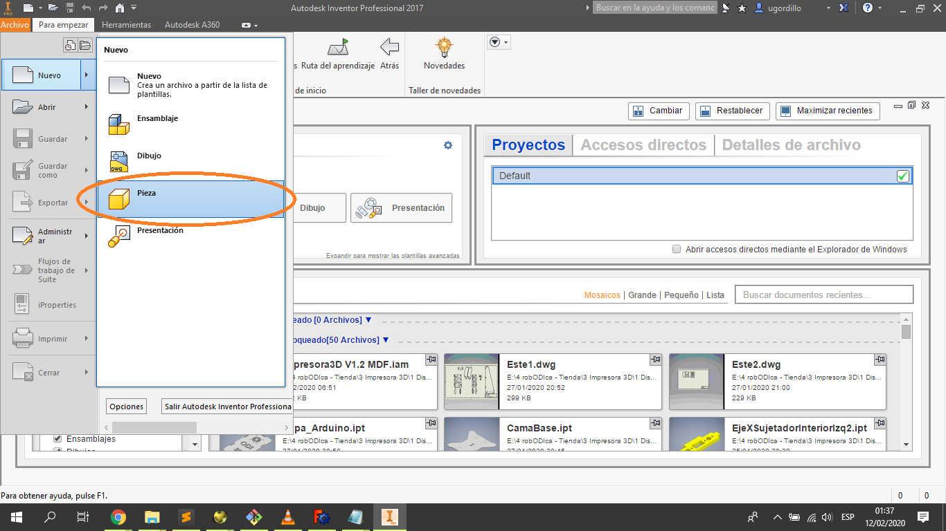
Raspsberry Project with INVENTOR
CAD Inventor software provides professional quality tools for 3D mechanical design, documentation and product simulation. Work efficiently with a powerful combination of parametric, direct, free-form and rule-based design capabilities.
Parametric Library
First a table of values was created for the design. It is the table:

Create a new design:
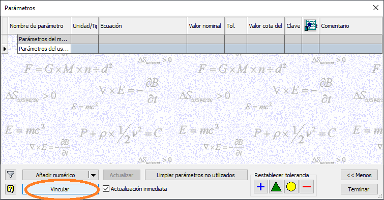
In this button is to add parameter:
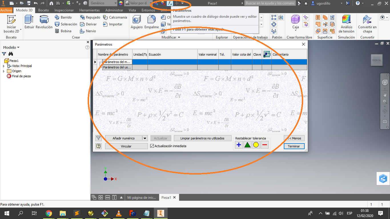
Add parameter:
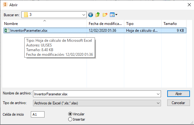
Select the excel file:
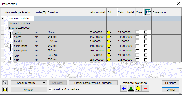
The table is add to INVENTOR with the same name:
Use the parameter to design:
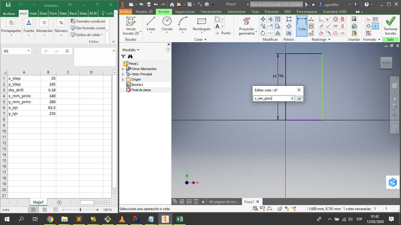
Use the parameter to design:
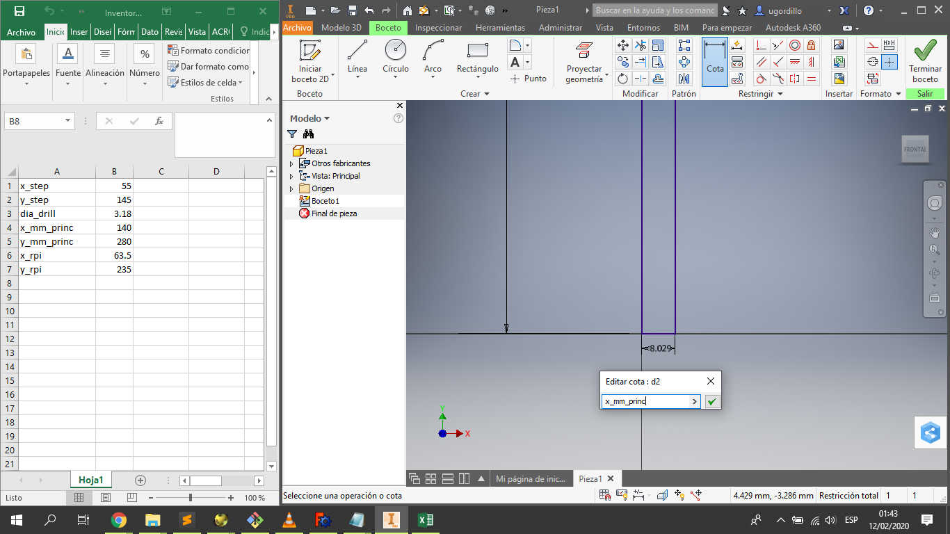
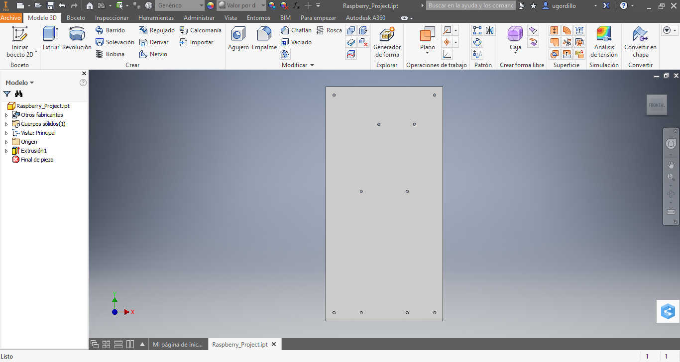
This is the design with Autodesk INVENTOR:
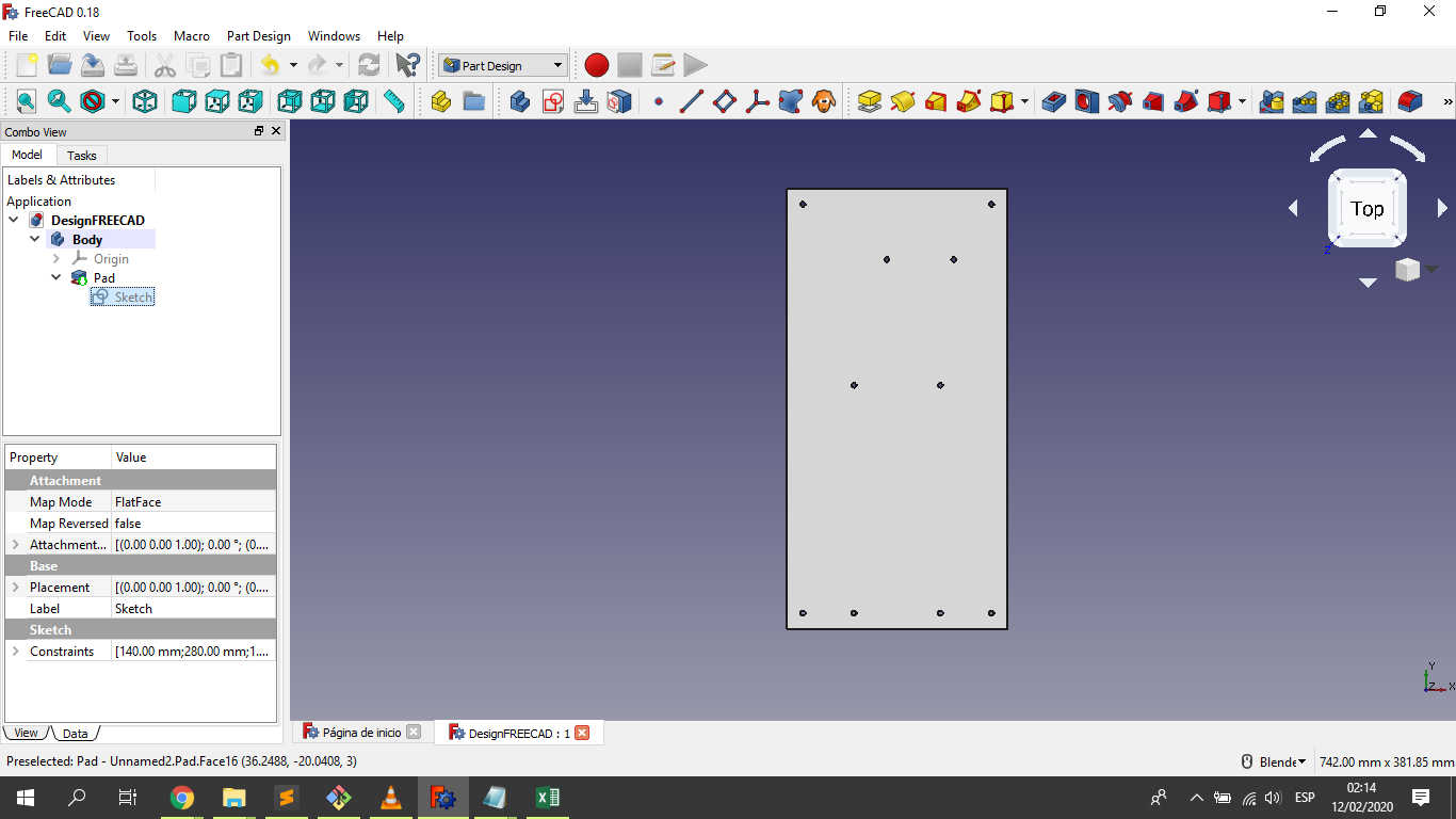
Raspberry Project with FREECAD
Create a new design:
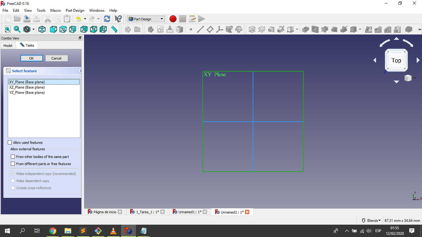
Use the parameter to design:
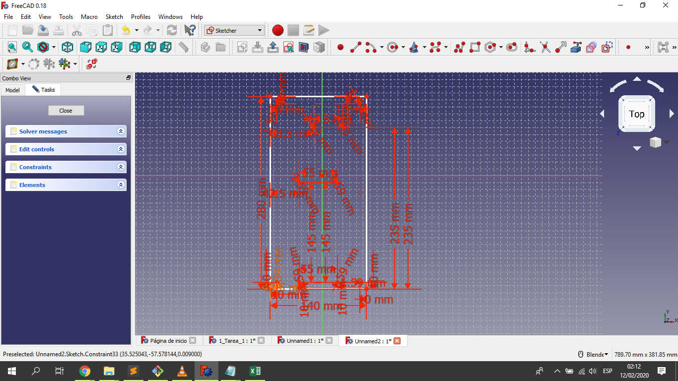
This is the design with FreeCAD:
Designed Files
| Description | Files |
|---|---|
| - Library | xy_drill.scad |
| - Example of Library | Test.scad |
| - OpenSCAD | Arduino_Module.scad |
| - OpenSCAD | Raspberry_Module.scad |
| - FreeCAD | DesignFREECAD.FCStd |
| - Autodesk Inventor | Raspberry_Project.ipt |
| - Parameters of Autodesk Inventor | InventorParameter.xlsx |
| - Cutting File | Module_Raspberry.dxf |