8. Computer controlled machining
Group Assignment
- Test runout, alignment, speeds, feeds, and toolpaths for your machine
Individual Assignment
- Make (design+mill+assemble) something big
GROUP ASSIGNMENT
This week I will work on design in a furniture object and I will fabricate it.
1. Designing the Pattern to Calibrate
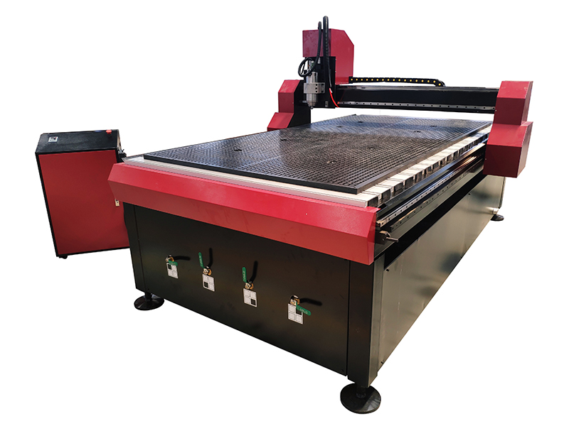
When we design a object big to assembly, we must take the correct junction method, because when we cut the part they do not fit in their holes; in the FABLAB Tecsup, I will use the VG1325 router from SUDA Company
    Volume to Work:
    Width = 1300 mm
    Length = 2500mm
    Height = 200mm
The design should be made according to the thickness of the MDF material:
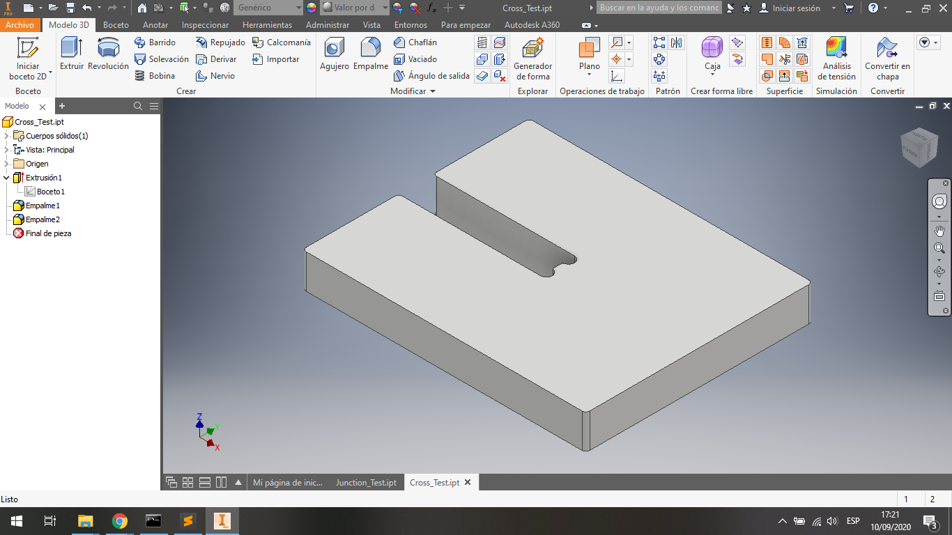
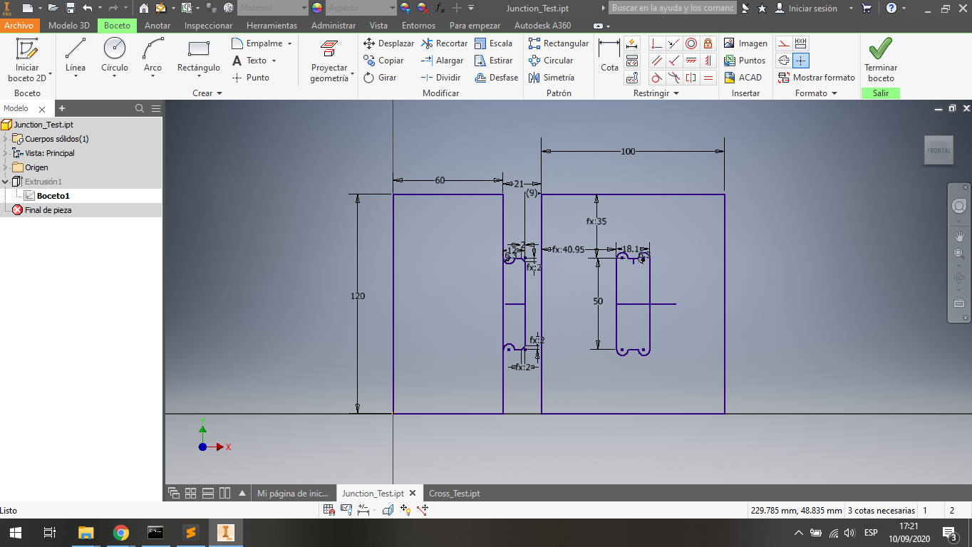
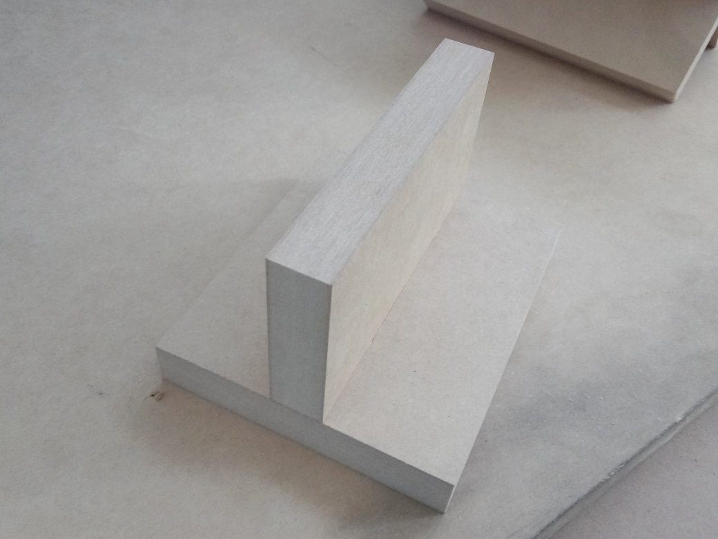
This piece is to crearte a junction in two same pieces:
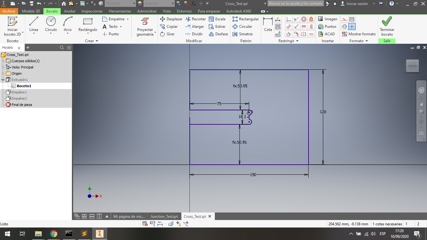
The final piece is similar to image:
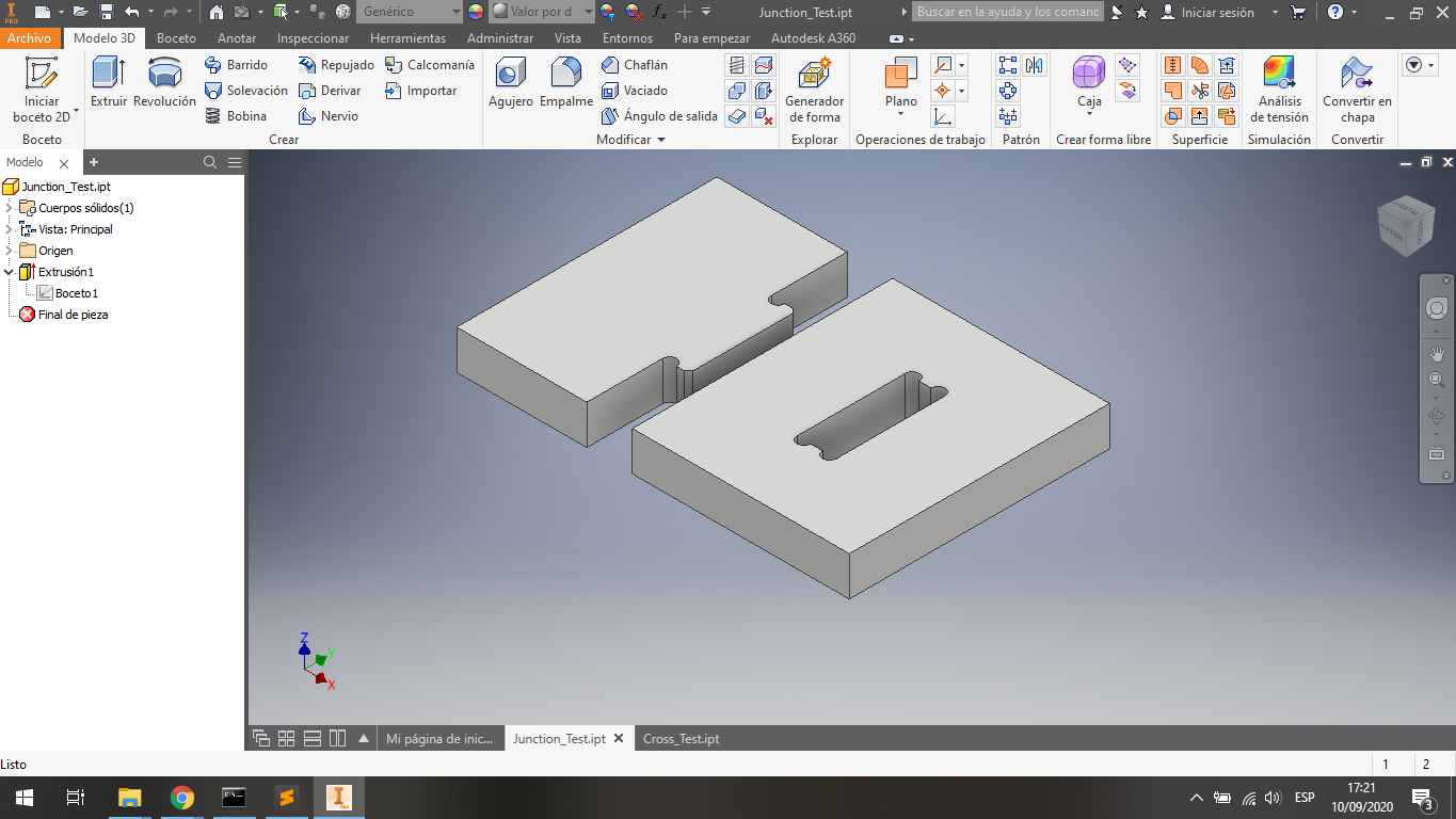
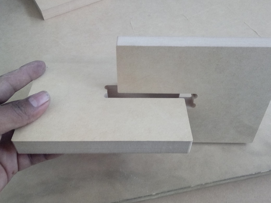
These second pieces are to create a non-through joint in a perpendicular way.
The final pieces are similar to image:
I create in Autodesk Inventor a DWG file with the two desings:
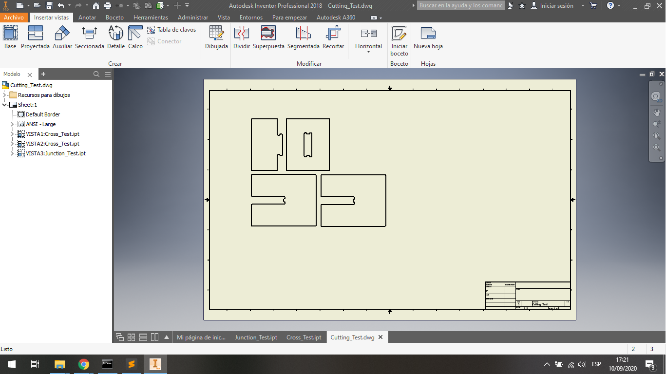
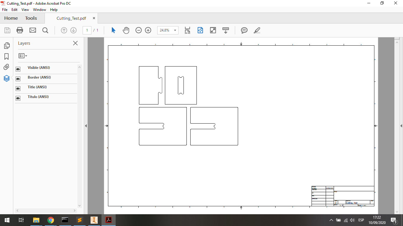
And I export the DWG file to PDF file; it is to work with Rhinoceros Software after:
2. Preparing the Pattern to Cut
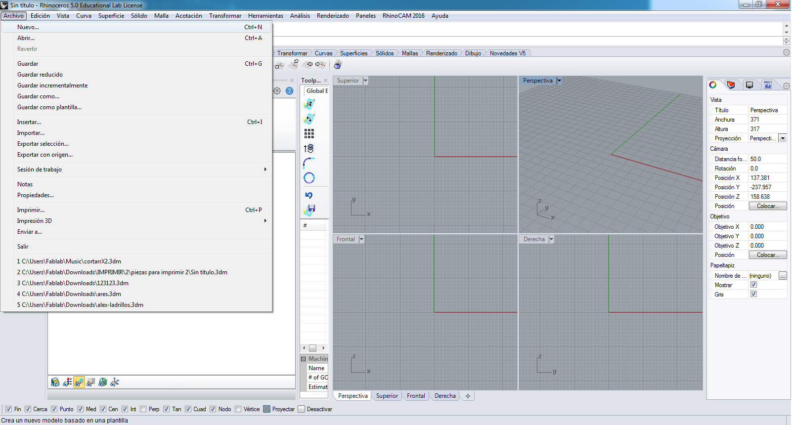
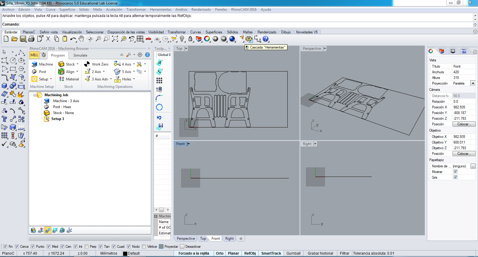
In fablab We have the RhinoCAM to work with the SUDA VG1325 machine, I open the software and create a new design:
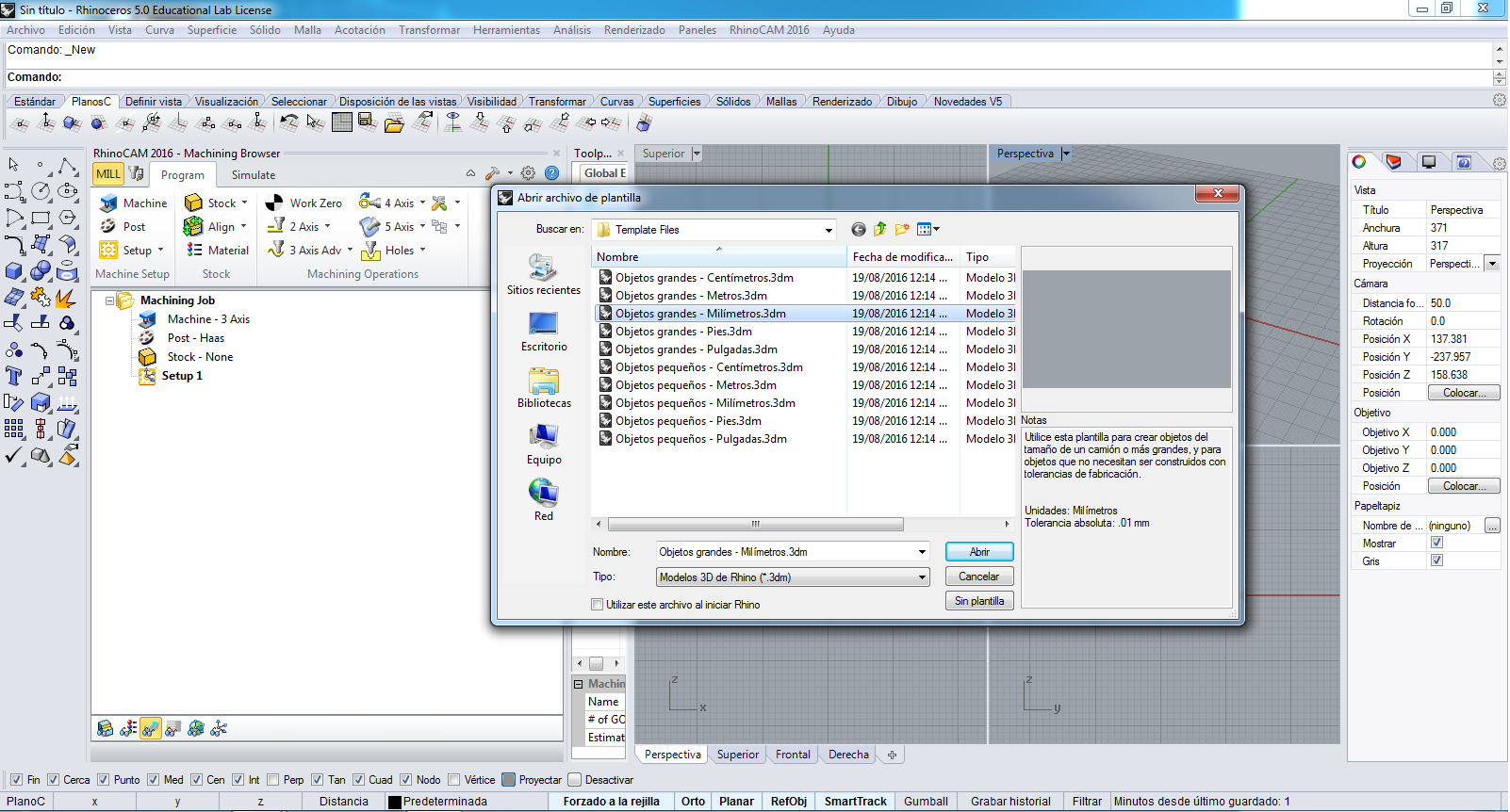
I choose the Large Objets - Milimeters design:
The apperance of Rhinoceros is here:
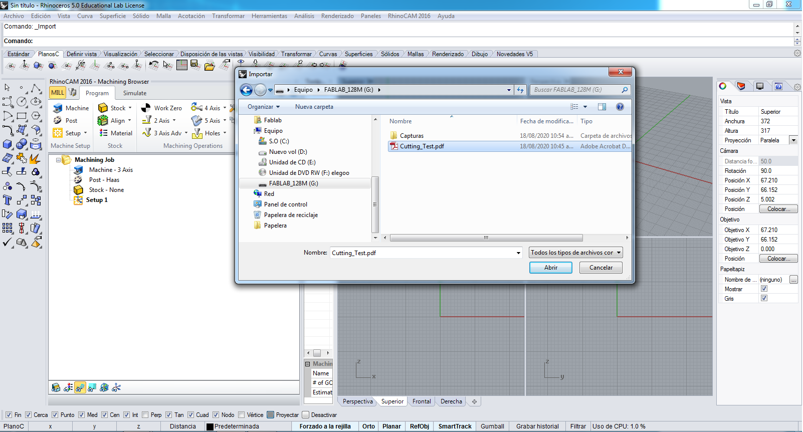
So, I import to Rhinoceros 5.0 the PDF file of before steps
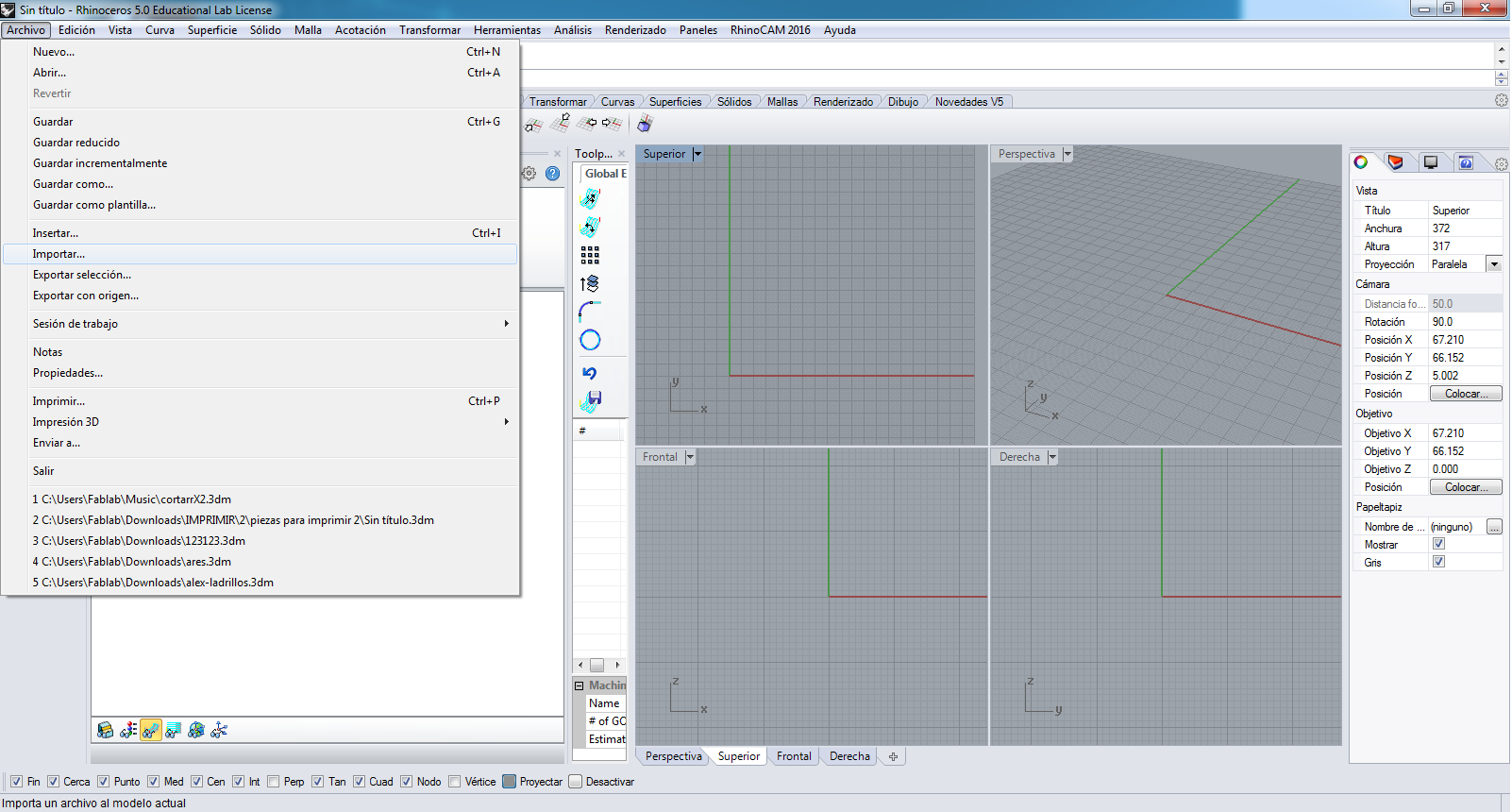
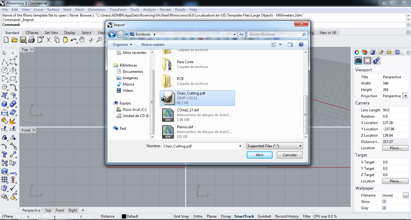
I choose the PDF file:
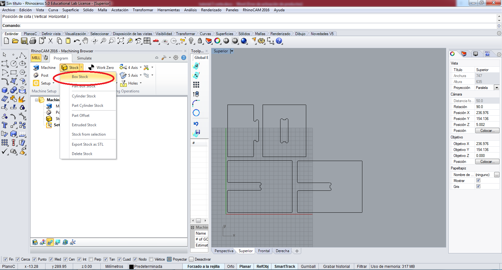
The design has some parts that are not important, for example the external square:
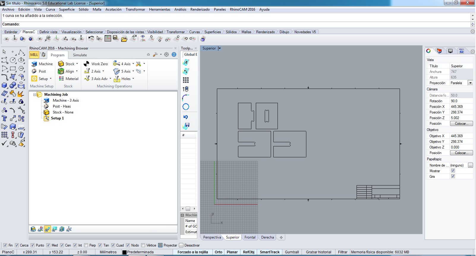
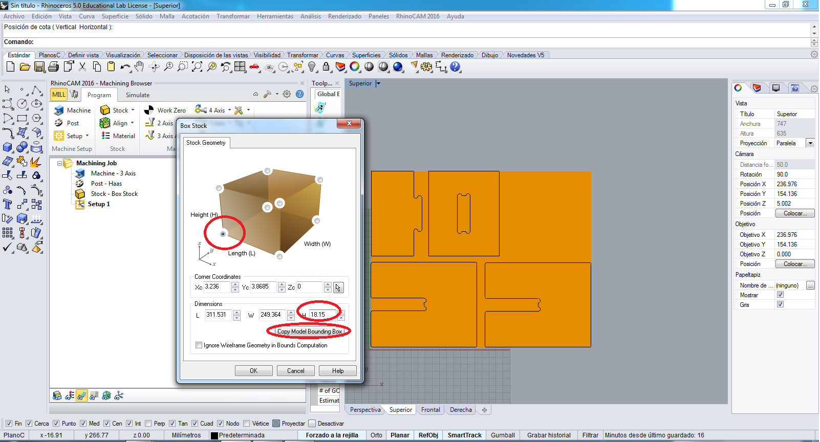
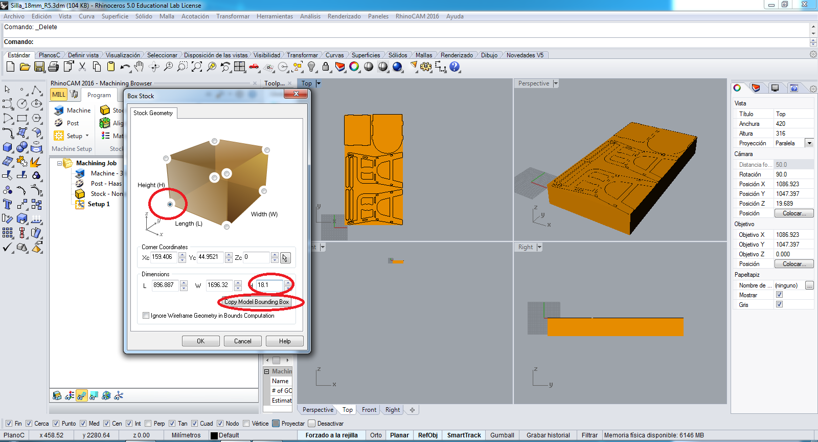
So I erased these parts and only I have the design pattern to cut, and to begin the configuration to cut, I click in Stock button and choose Box Stock:
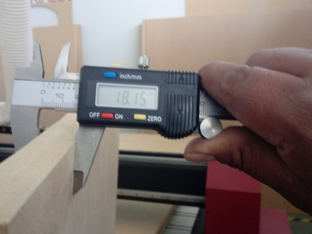
Now, I click in Copy Model Bounding Box button to copy the area to work, and I write the thickness in H, that is 18.15 mm in my case:
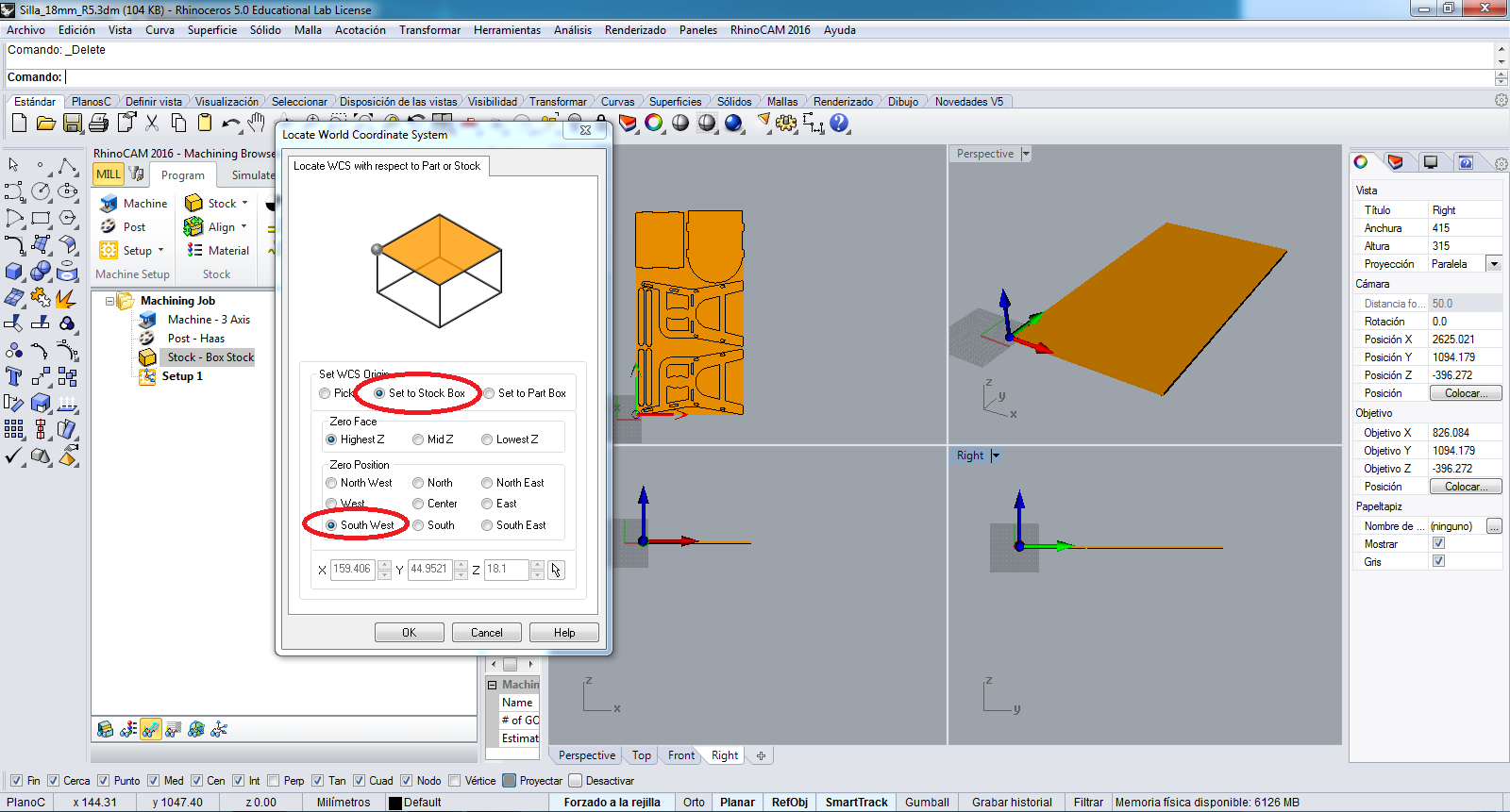
In Align button I choose the Set World CS option:
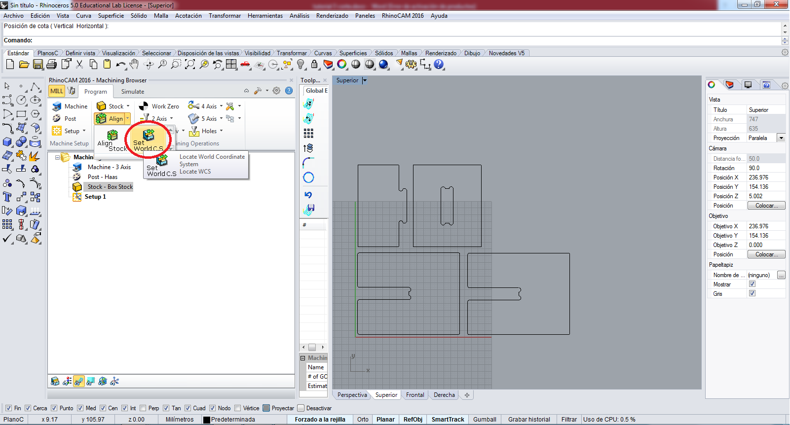
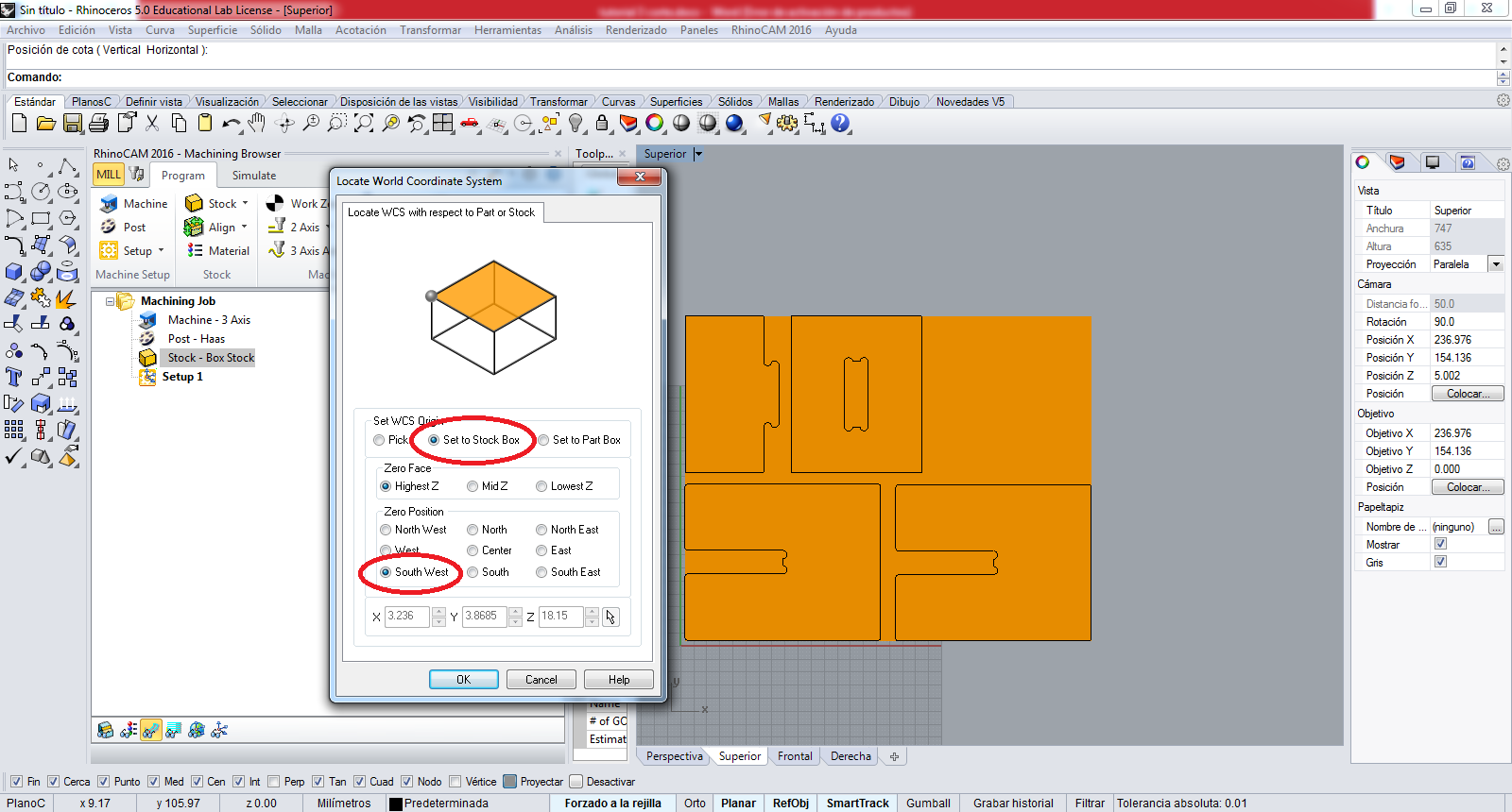
For align I select the Set to Sotck box and the South West to set:
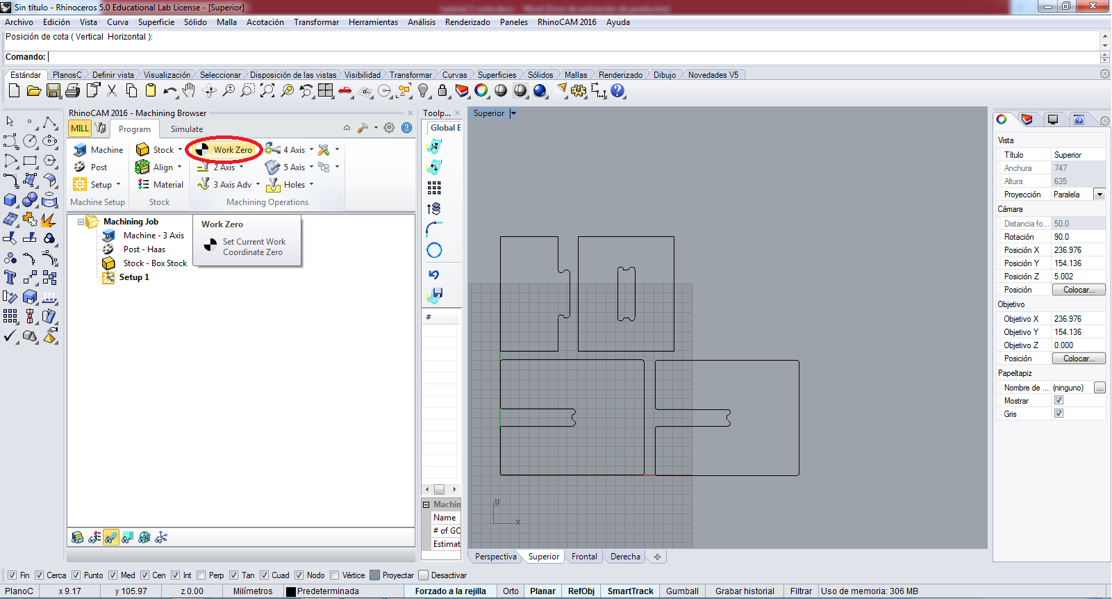
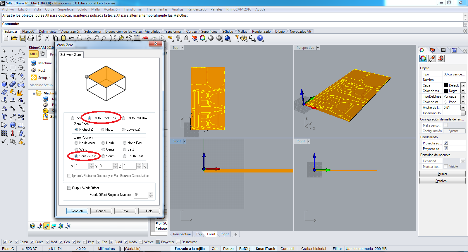
Now I click to Work Zero button:
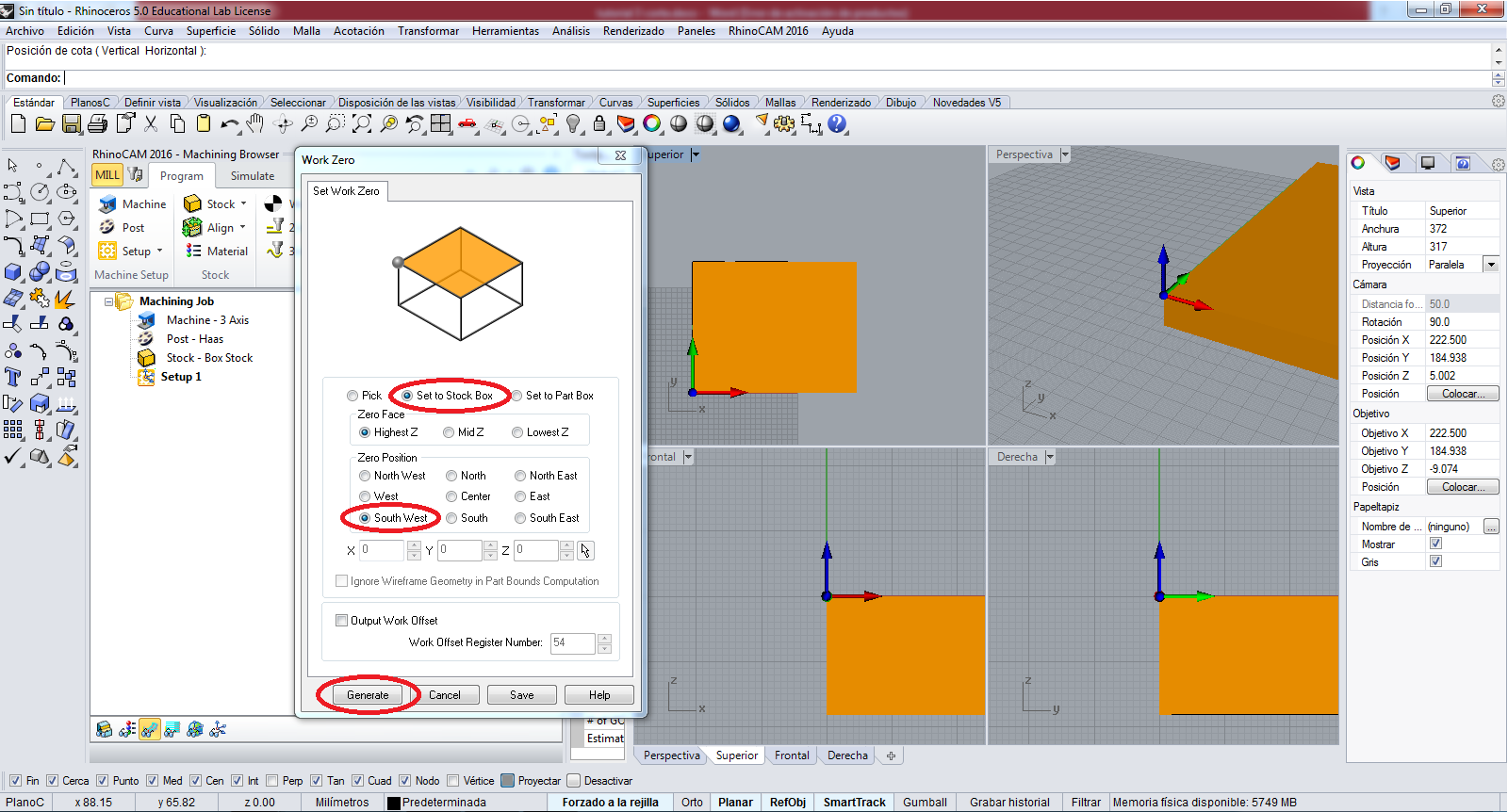
For Work Zero I choose the Set to work Box and South West options to set and I click in Generate button:
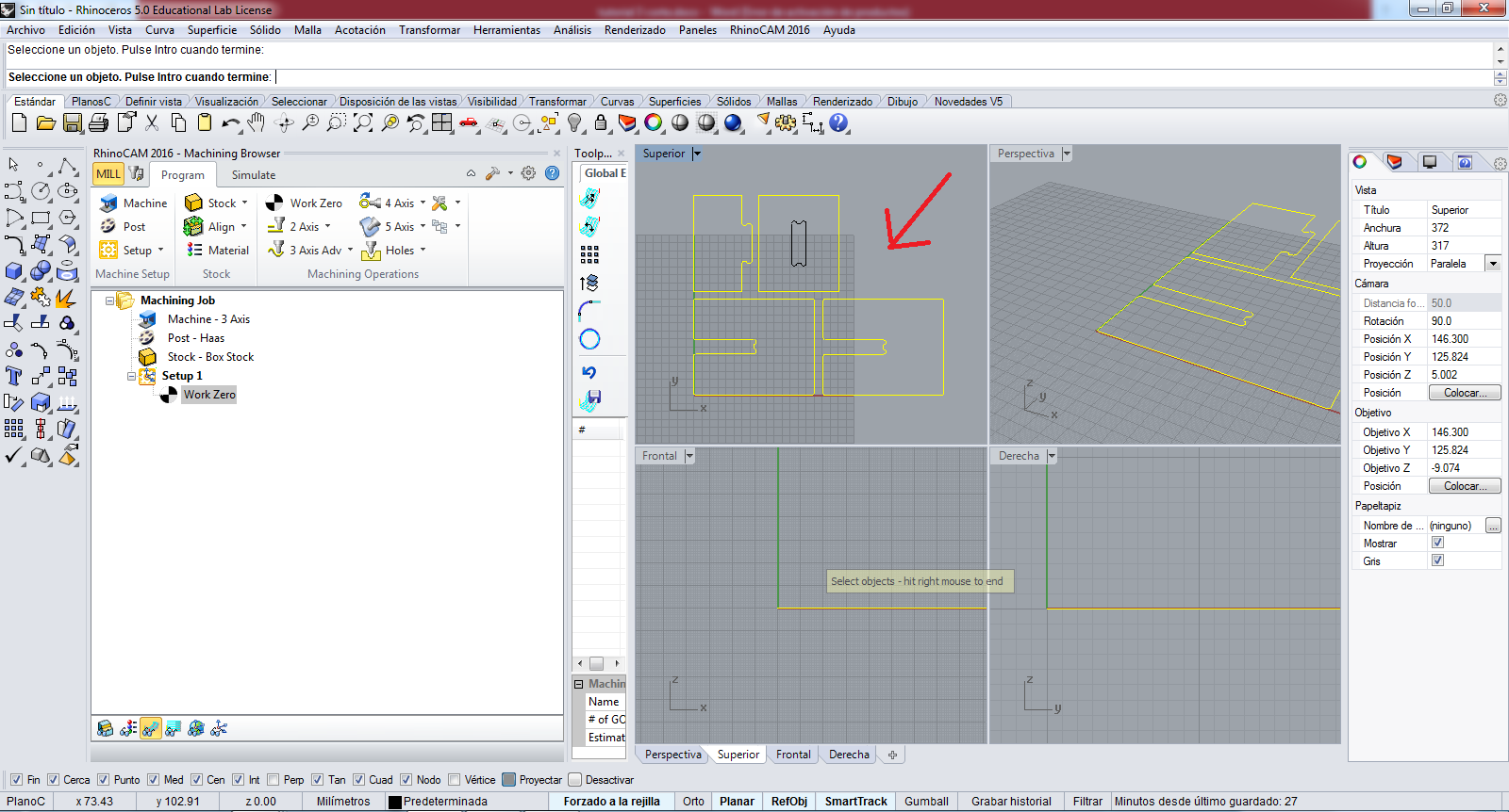
A TIP: in this part the reference to design is moved, some measure down, I must moved all design to Zero point:
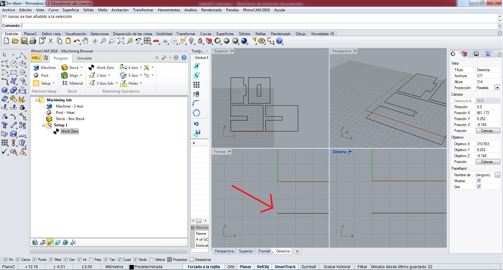
So I select all design and I moved to the work zero, we can see in the image:
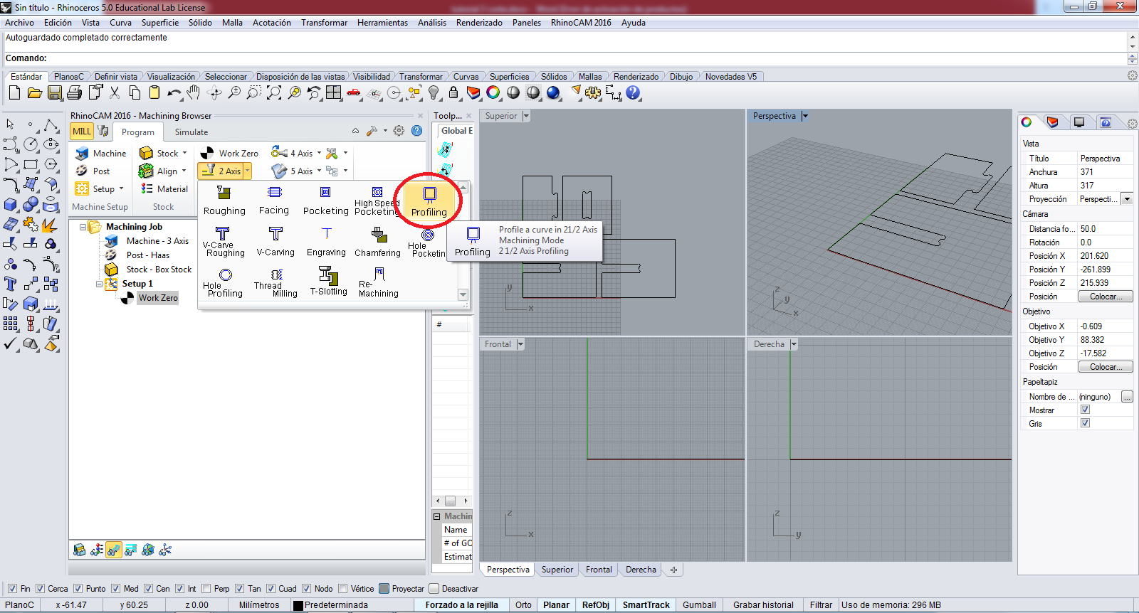
Now we are ready to generate the works, first I create the cutting work; I select in 2 Axis button the Profiling option:
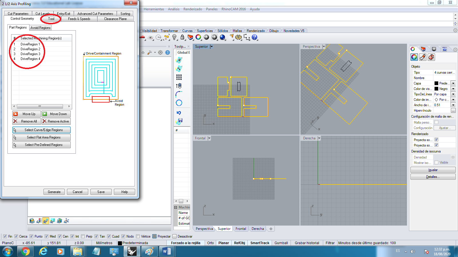
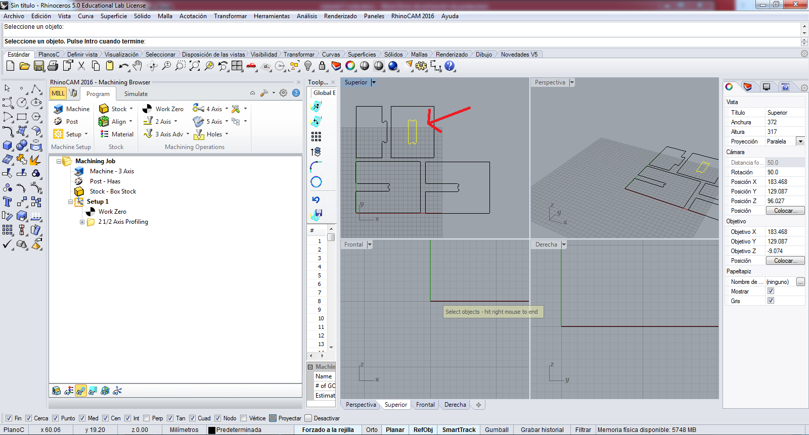
In the Control Geometry tab I add the Regions to work, I click in Select Curve/Edge Regions to Add:
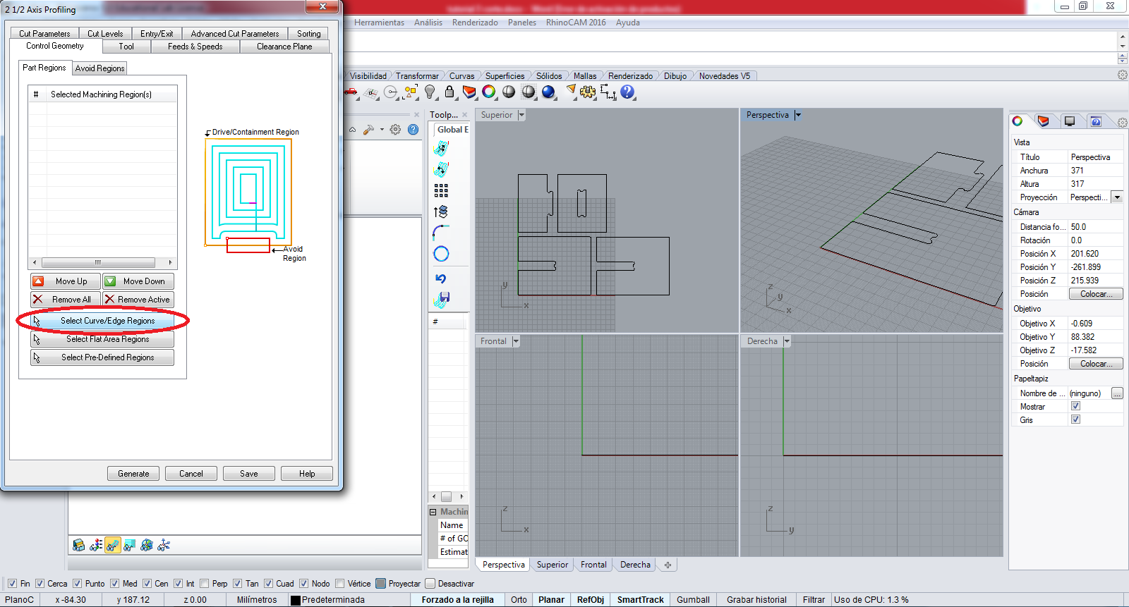
I select all the geometries to cutting, we can see in the image, and press the ENTER key of keyboard to finish add:
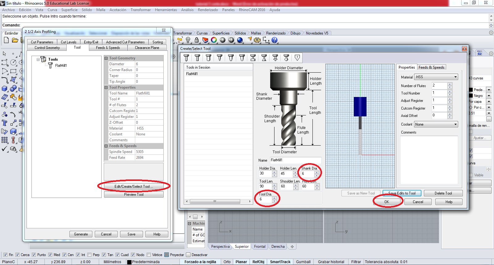
We can see at the list, to next I click in Tool tab:
In the tool tab, I can edit the cutting tool, we can see in the image:
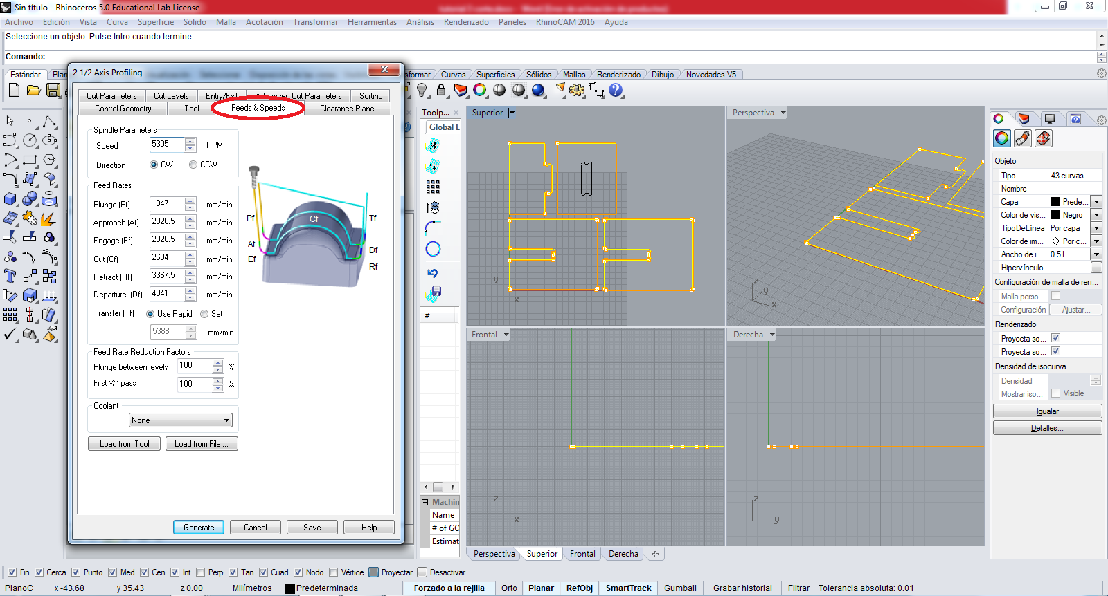
In the Feeds and Speeds the parameters are the following:
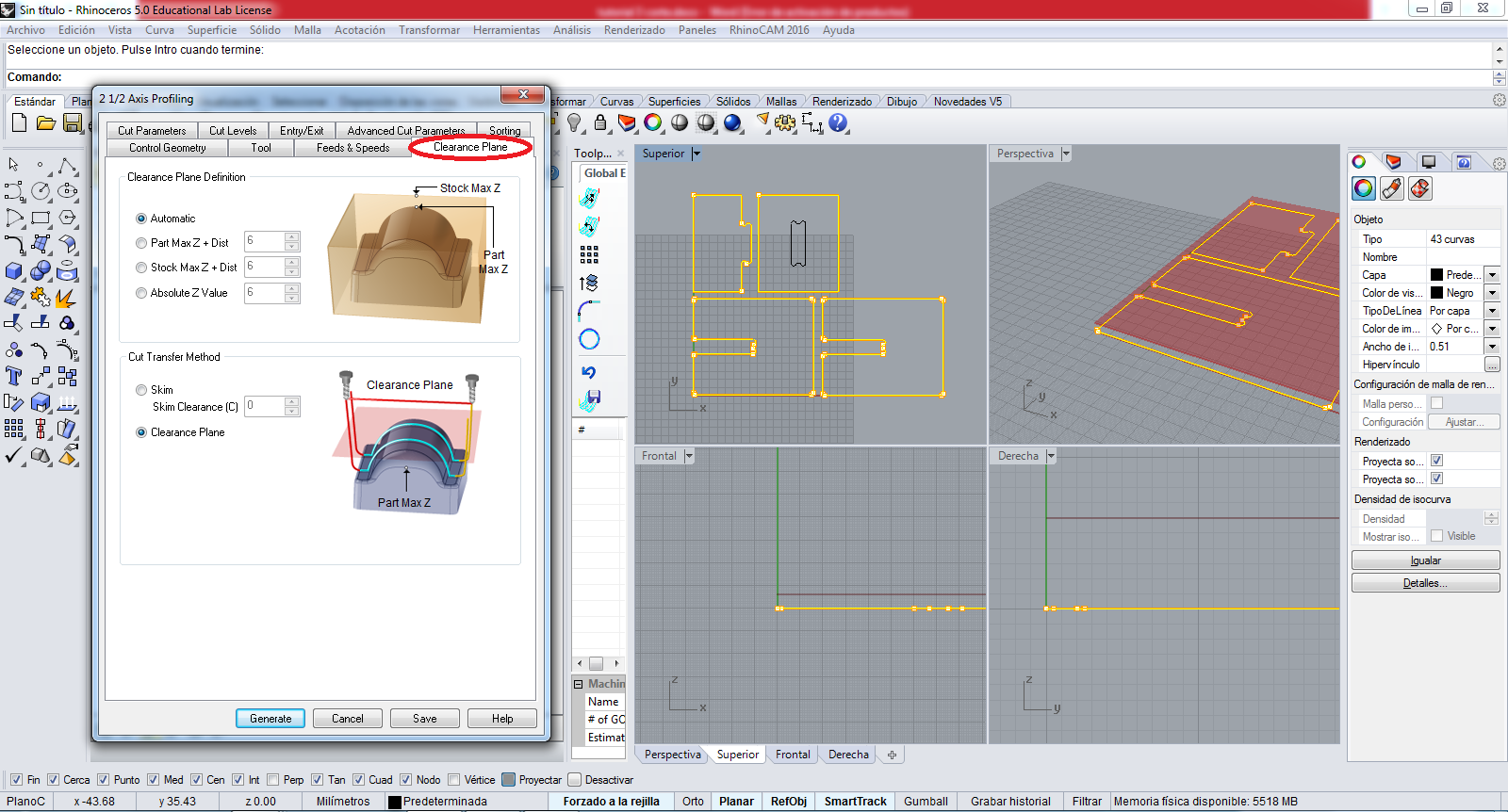
In the Clearance Plans tab the parameters are the following:
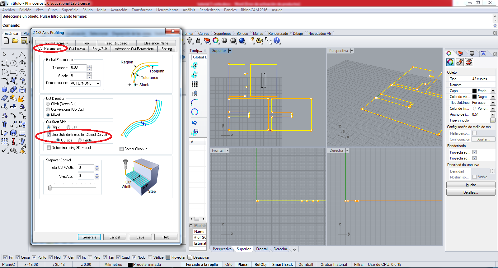
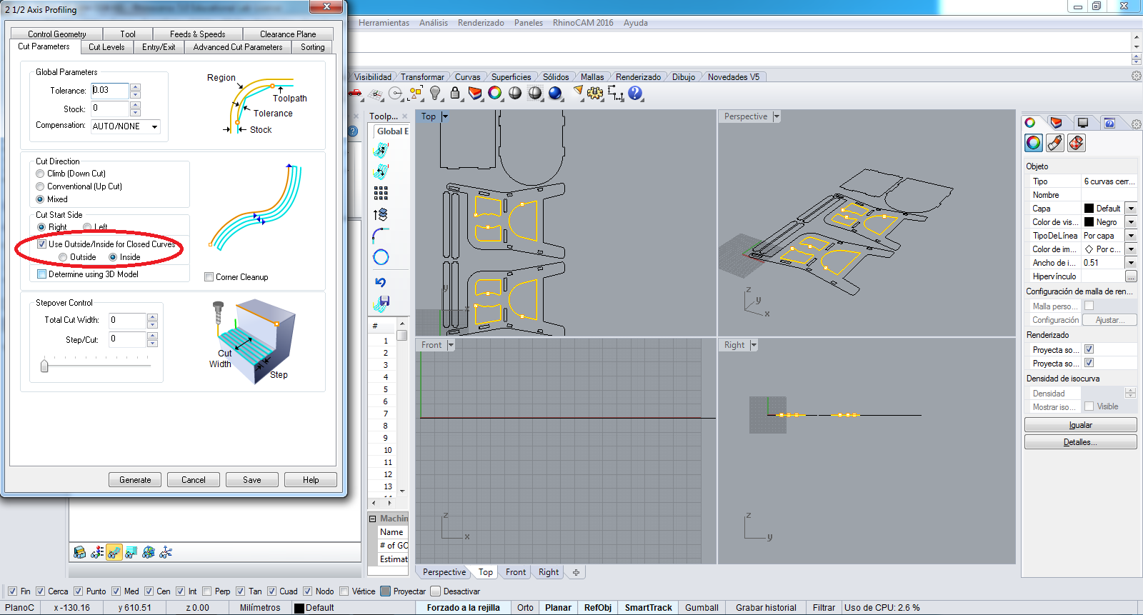
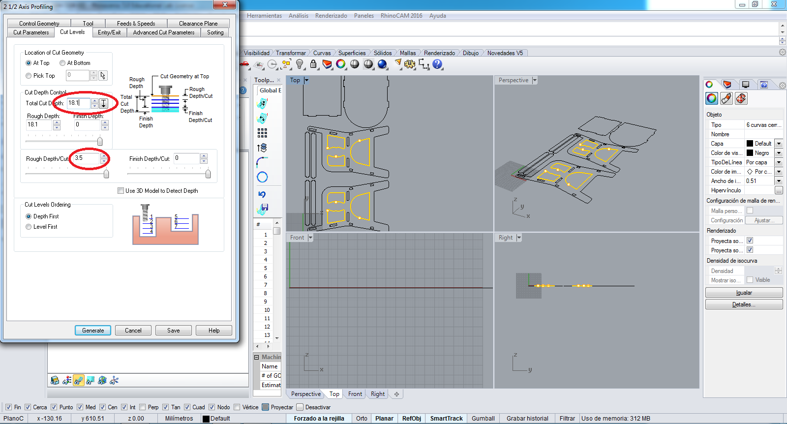
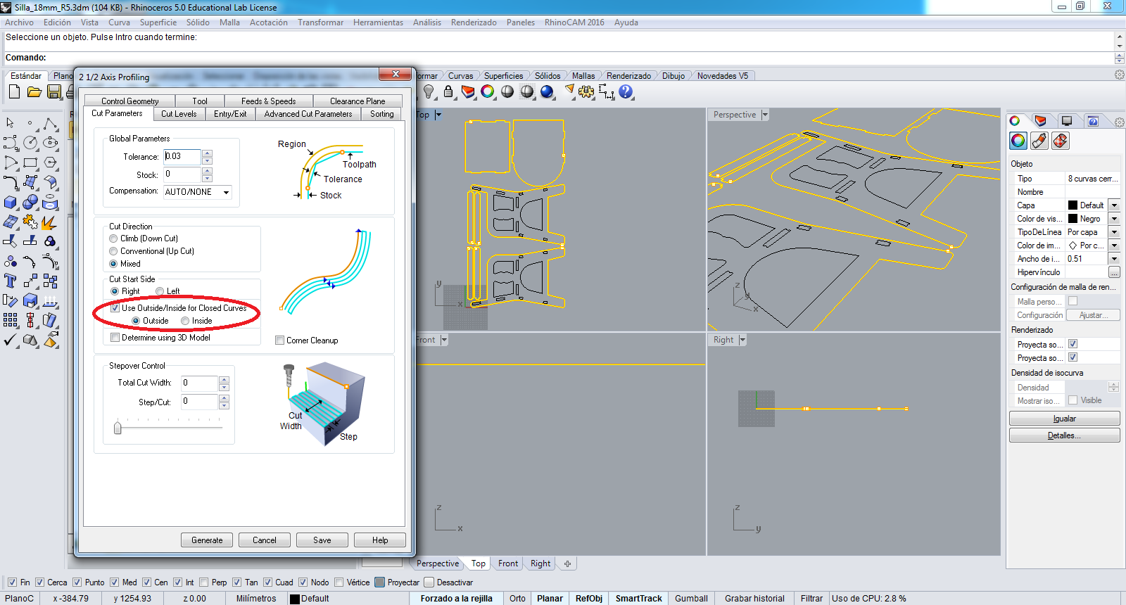
In the Cut Parameters tab I choose the Outside option to work:
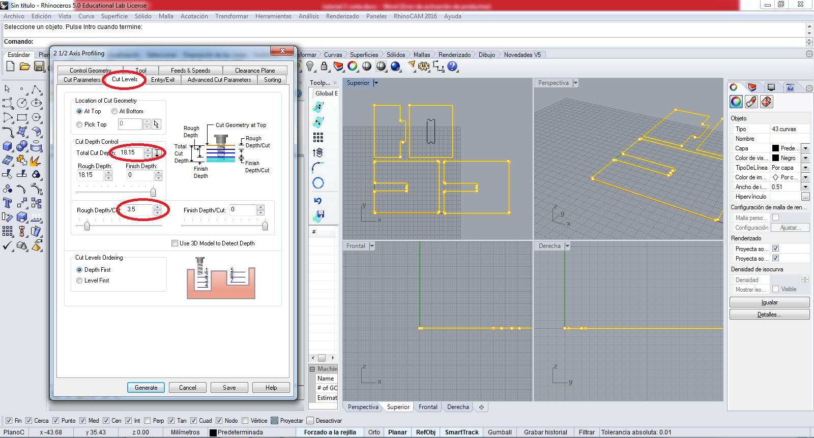
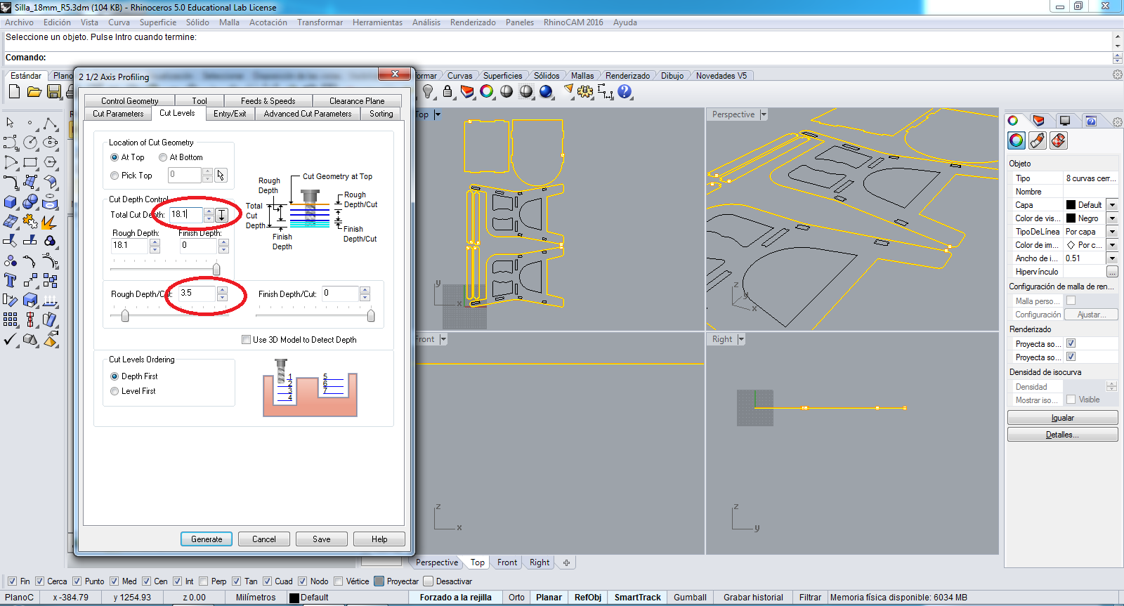
In the Cut Levels tab I colocate the thickness material of MDF and the cutting step, in my case is:
    Thickness = 18.15 mm
    Cutting Step = 3.5mm
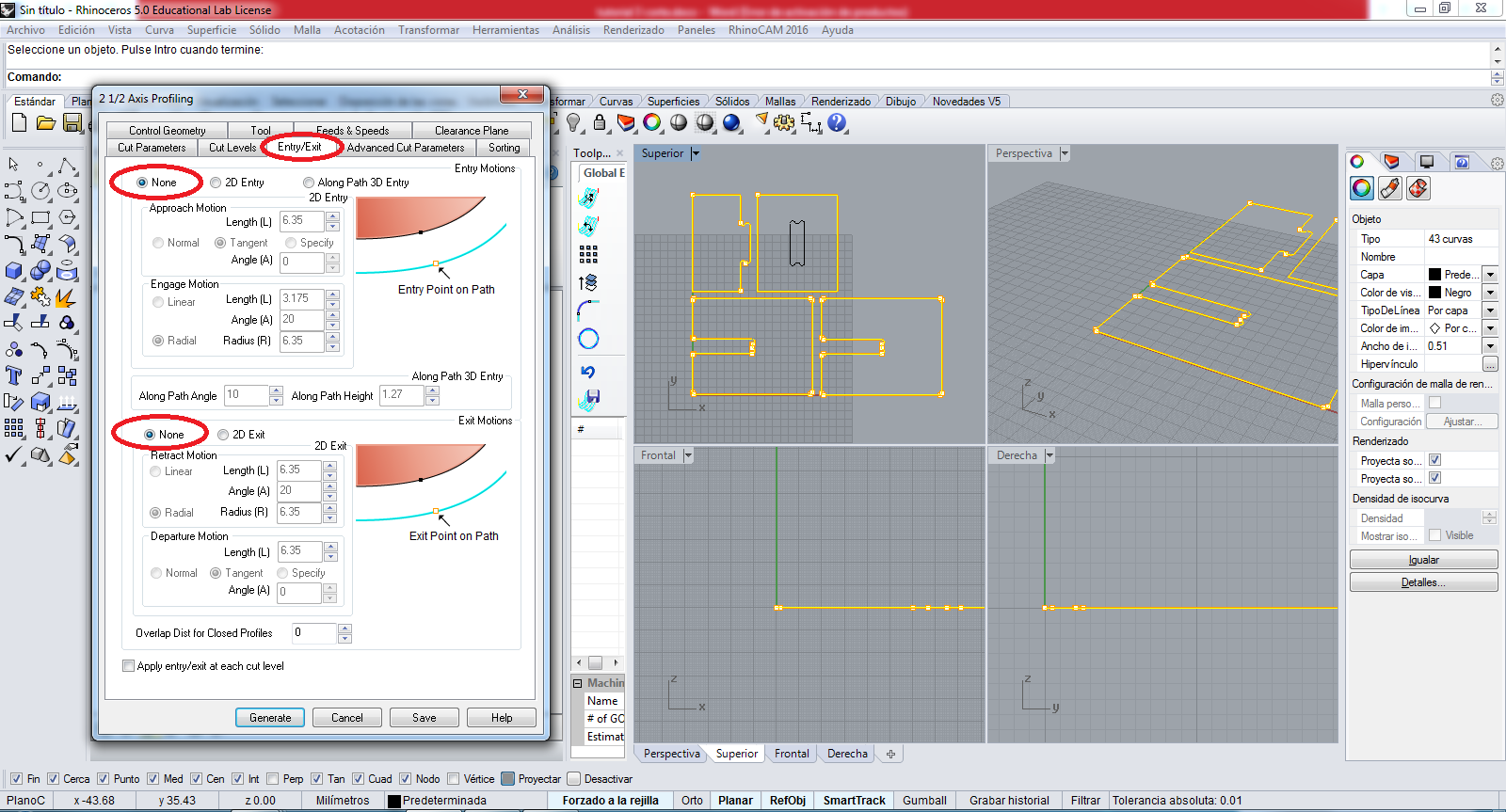
In the Entry/Exit tab I choose the None Entry and None Exit:
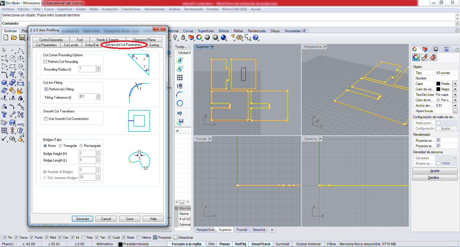
In the Advanced Cut Parameters tab the parameters are the following:
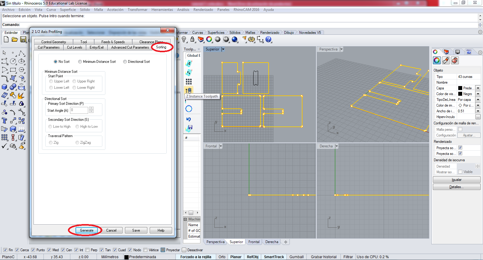
In the Sorting tab the parameters are the following, and I press the Generate button to generate the job:
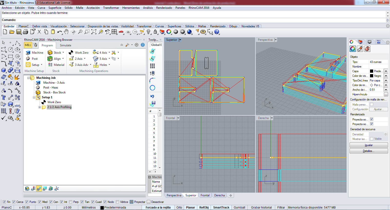
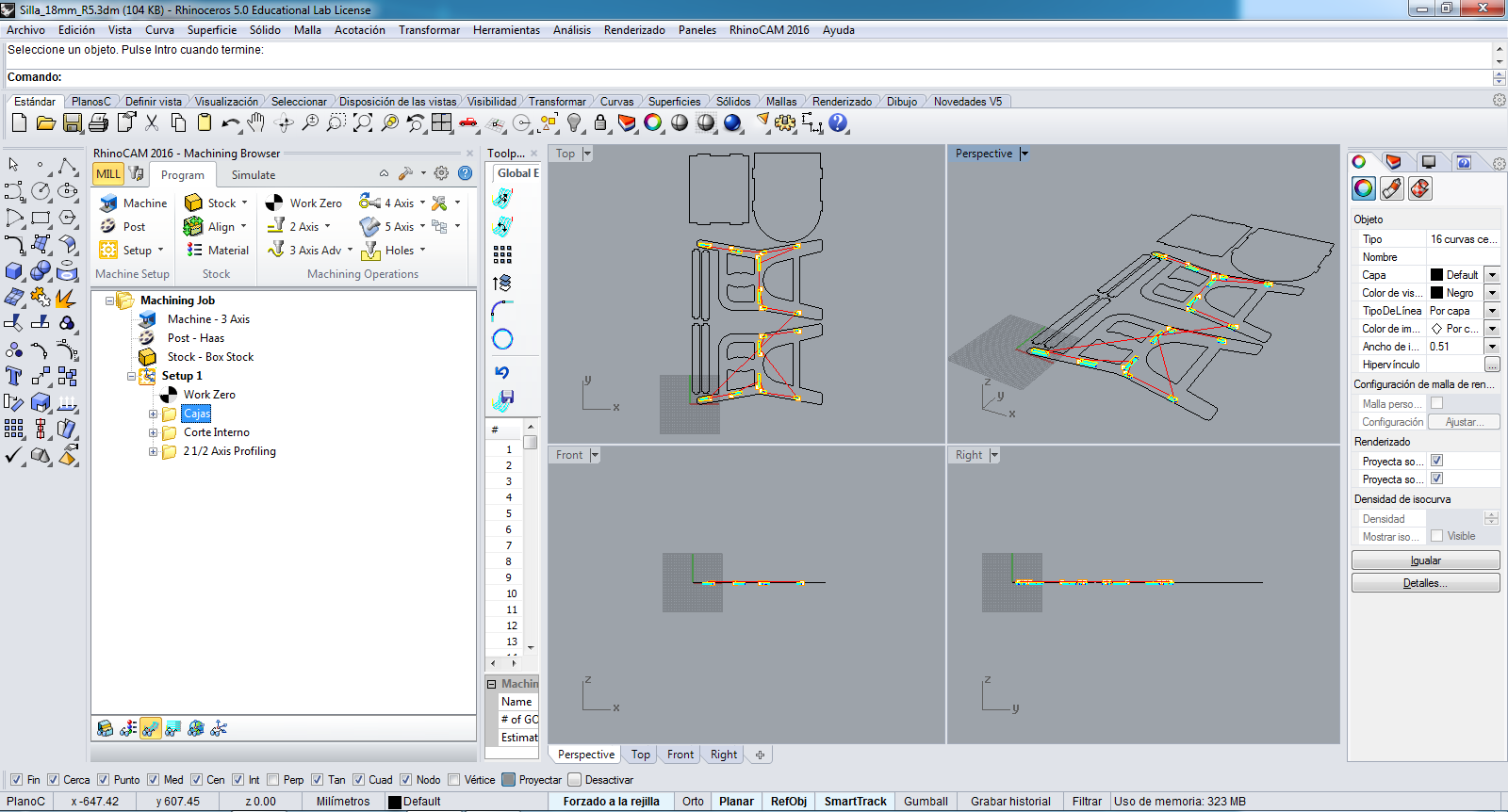
So the work shows as in the image:
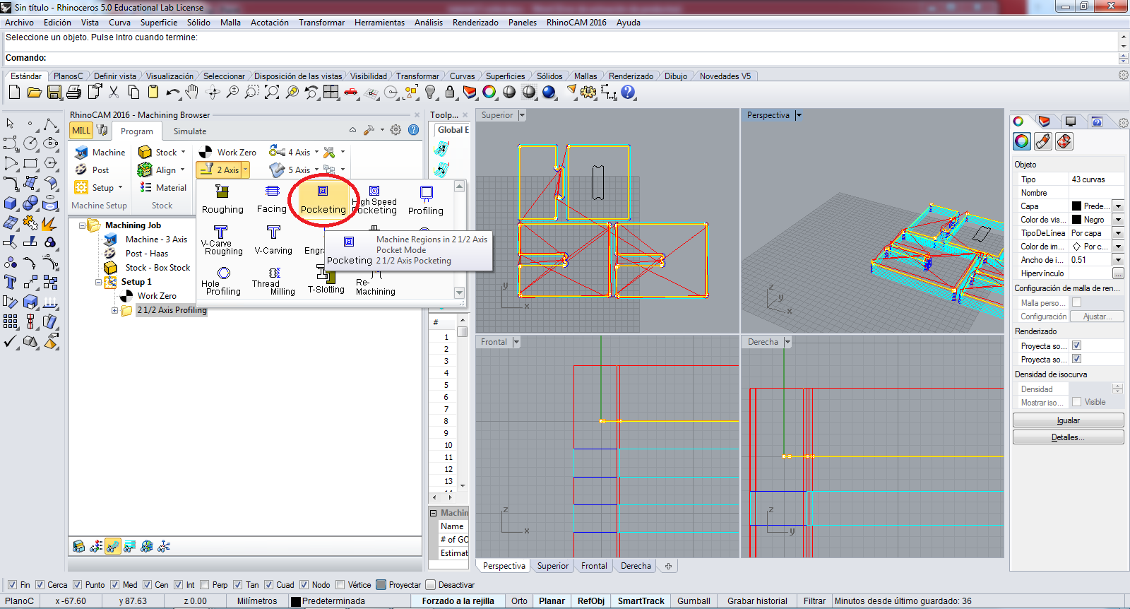
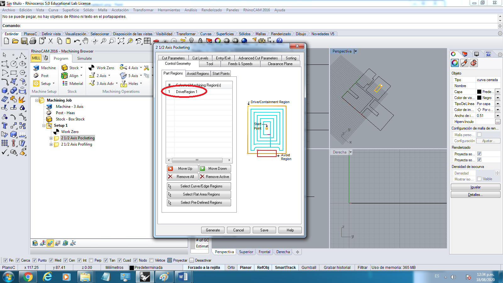
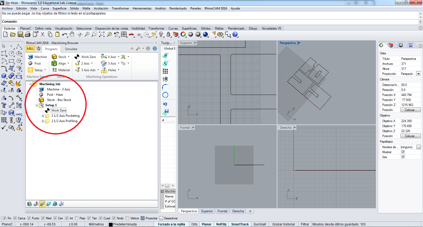
Now I create the Job to the POCKETING process, I select in 2 Axis button the Pocketing option
In the Control Geometry tab I add the Regions to work
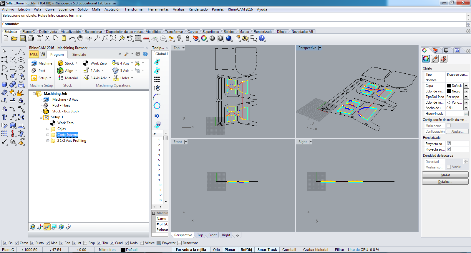
I click in Select Curve/Edge Regions to Add the signed region:
In the Tool tab, I can edit the cutting tool, the configuration is the same
In the Feeds and Speeds tab, the configuration is the same.
In the Clearance Plans tab, the configuration is the same.
In the Cut Parameters tab, the configuration is the same to defaults.
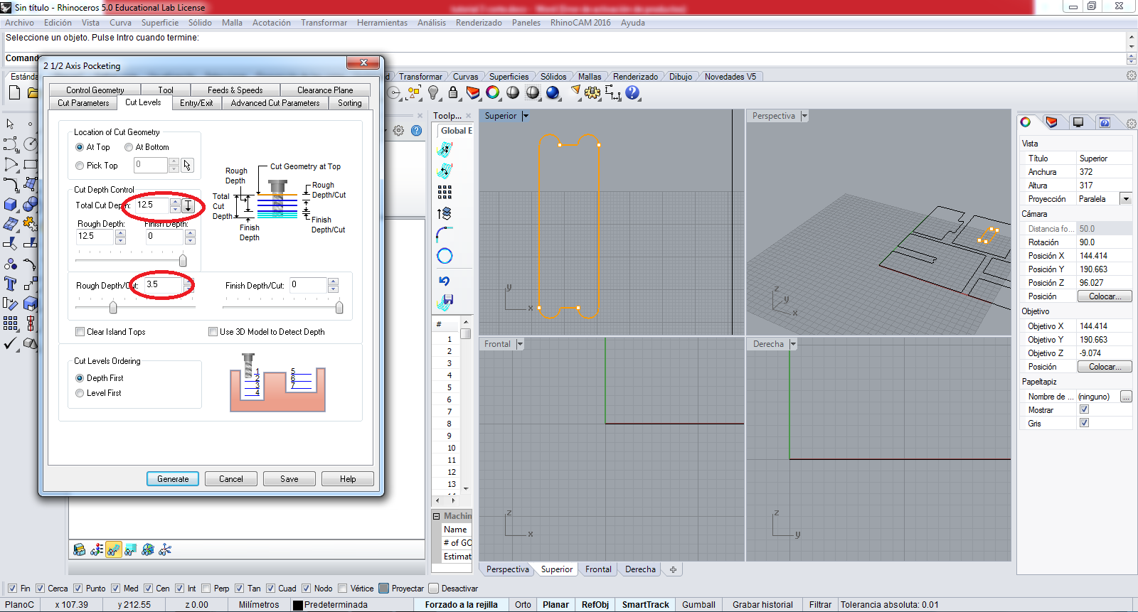
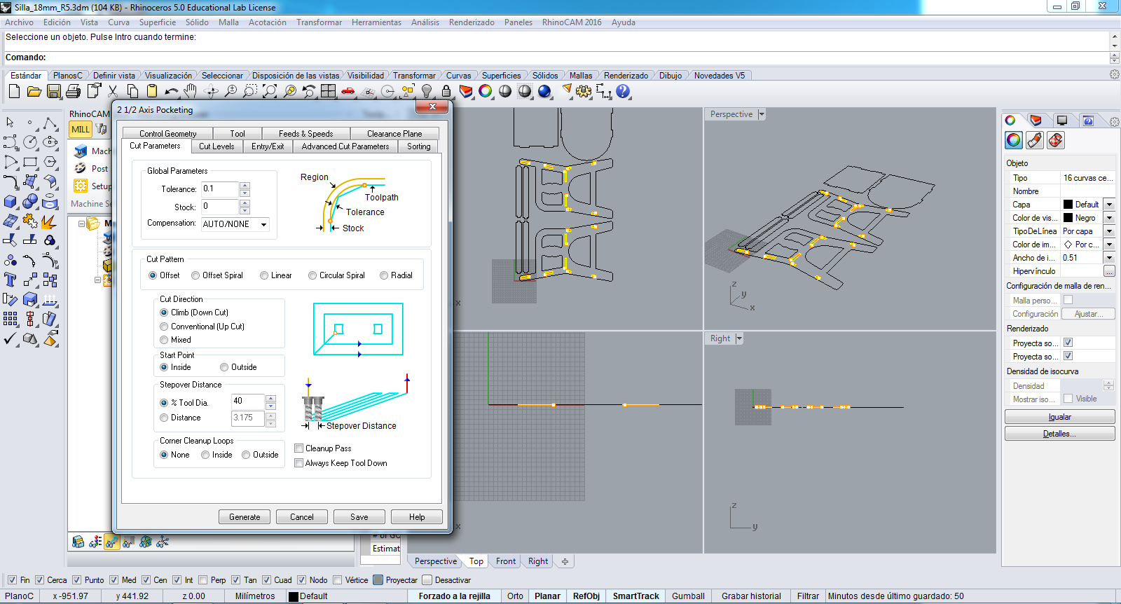
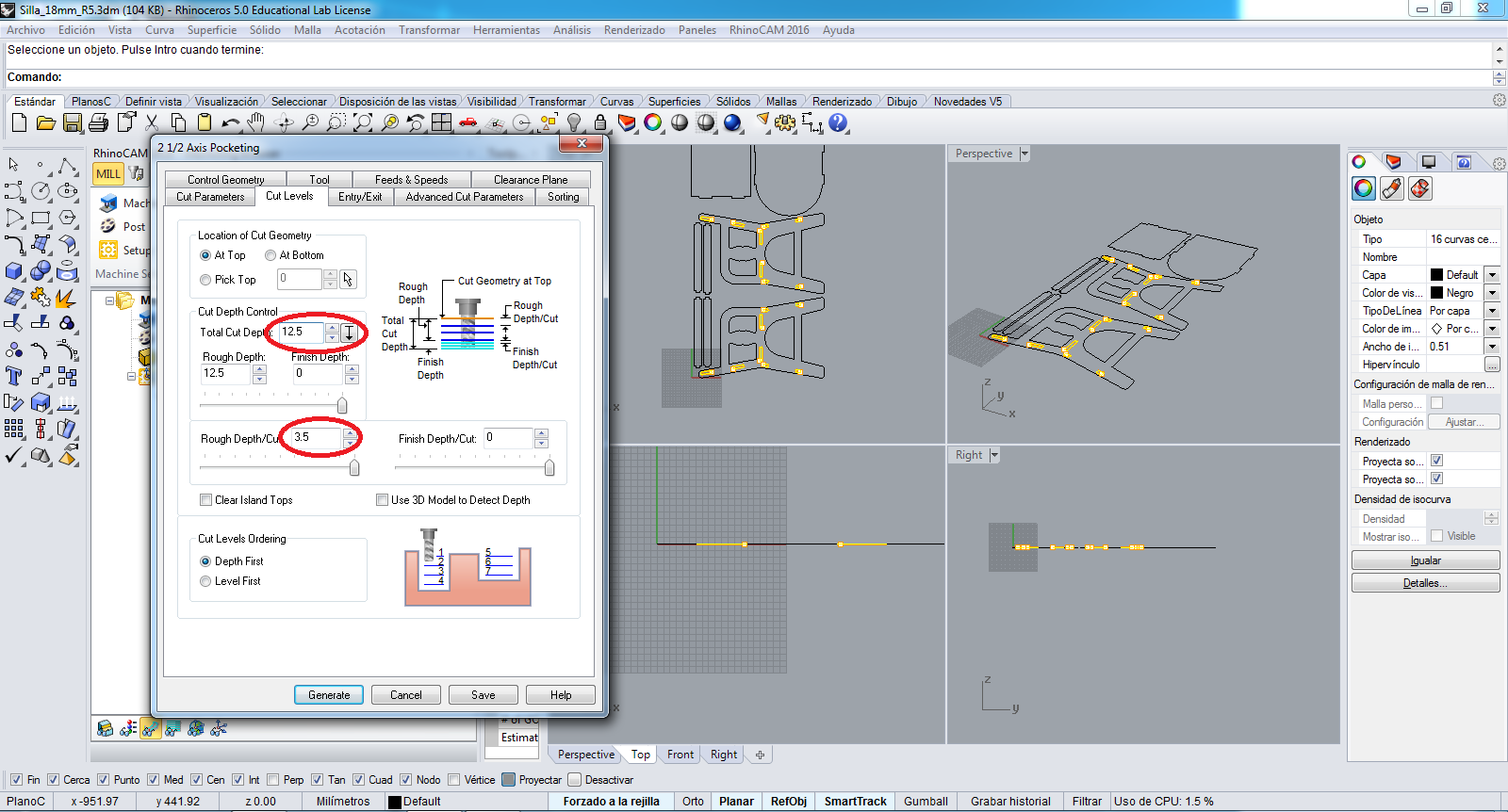
In the Cut Levels tab I colocate the thickness material of MDF and the cutting step, in my case is:
    Thickness = 12.5 mm
    Cutting Step = 3.5mm
In the Entry/Exit tab, the configuration is the same.
In the Advanced Cut Parameters tab, the configuration is the same.
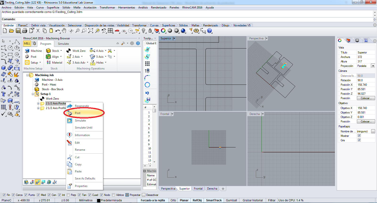
In the Sorting tab , the configuration is the same, and I press the Generate button to generate the job:
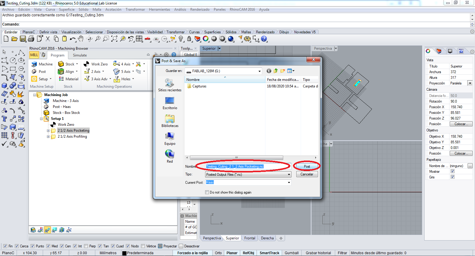
Afterwards I post the NC file in my computer:
I save the MC file with a coherent name to POCKETING file:
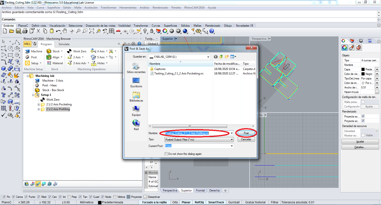
Now I repeat the before actions to PROFILING fiel:
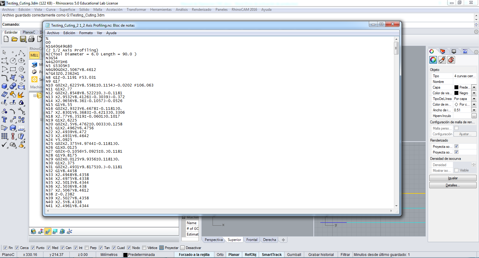
The files have the gcodes in the texts:
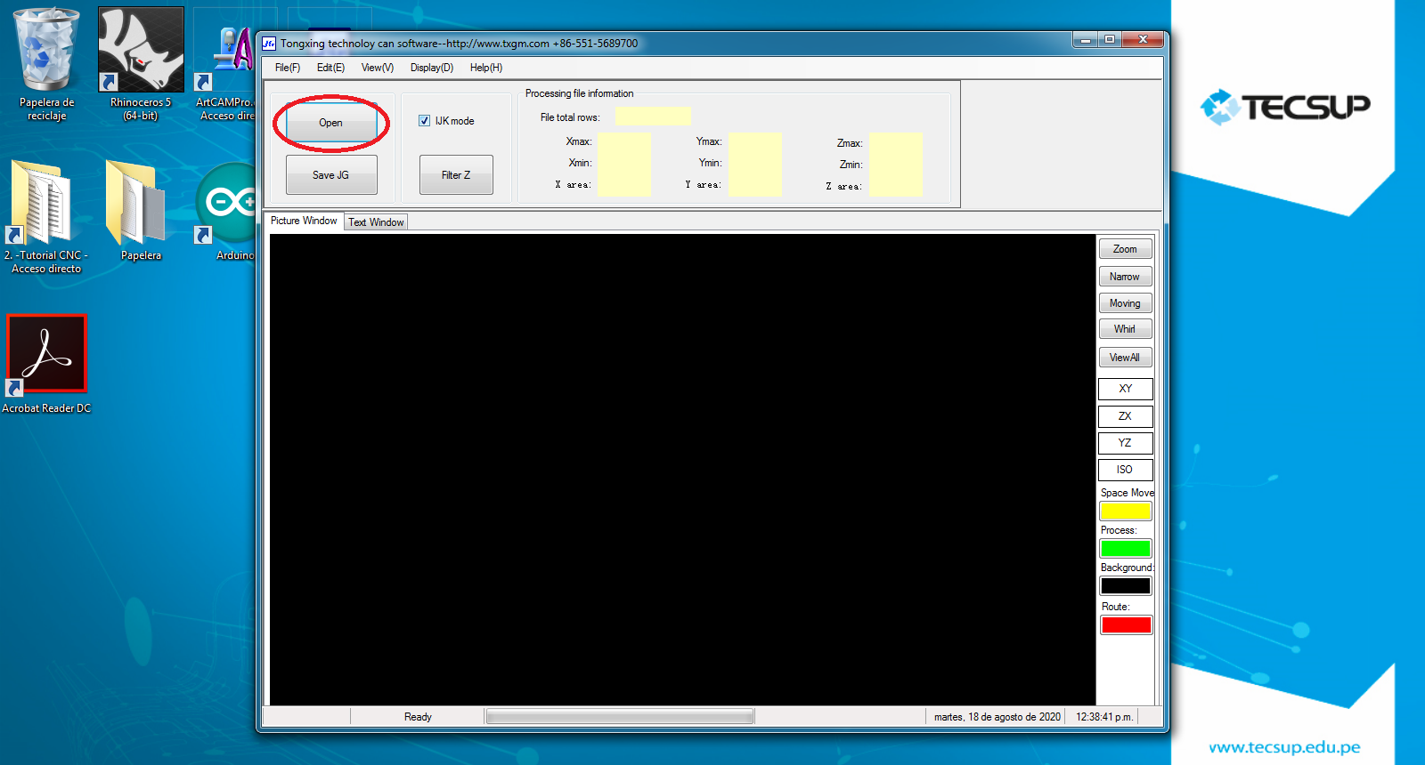
Afterwards, I convert the GCODE file to JG file that is the file used to VG1325 Machine:
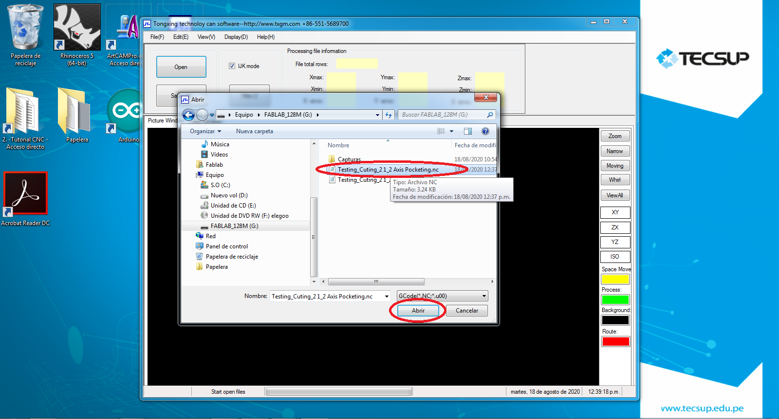
Now, I click the OPEN button to open the file:
I select the NC file to convert:
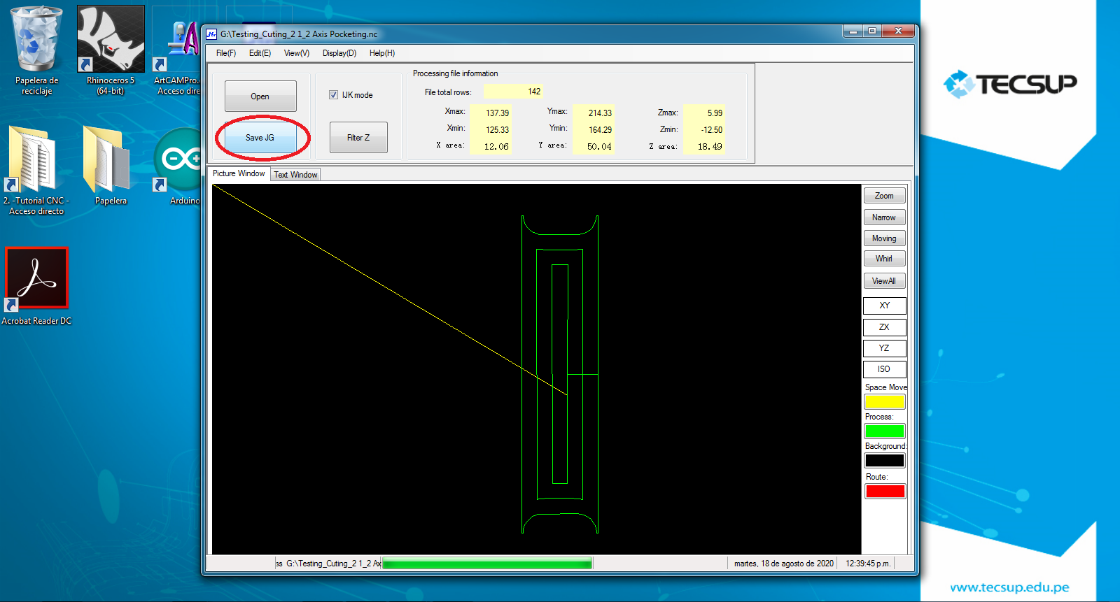
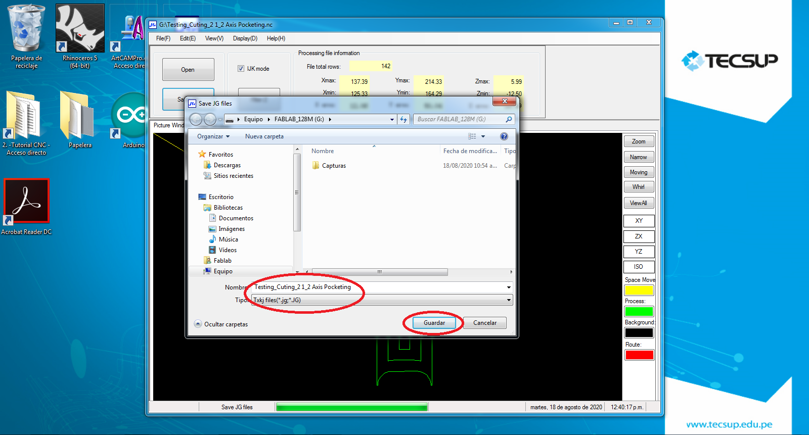
So, I click the SAVE JG to the design in JG file:
And, I colocate the name and save the POCKETING design:
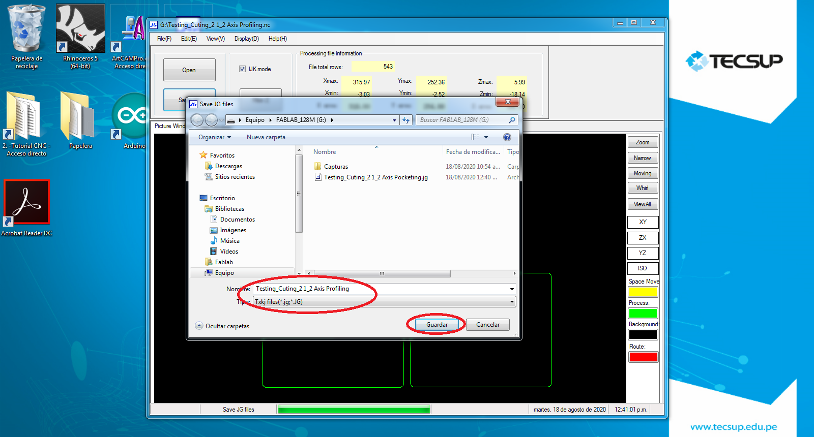
Finally, I repeat the before steps to save the PROLIFING design:
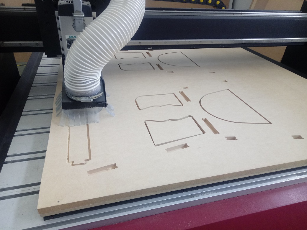
3. Cutting the Pattern
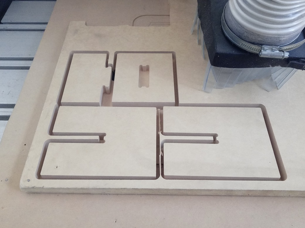
The JG file load to the machine and start the cutting:
The process to cutting, we can see in the following video:
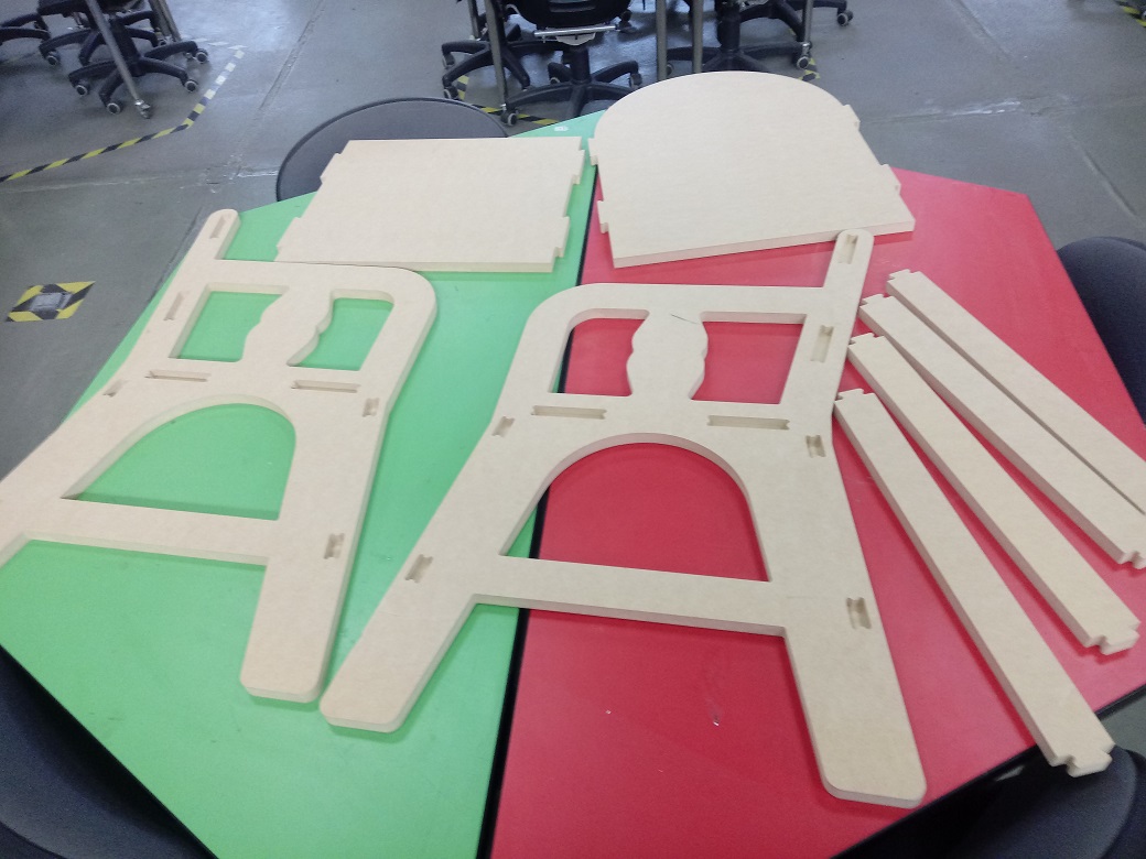
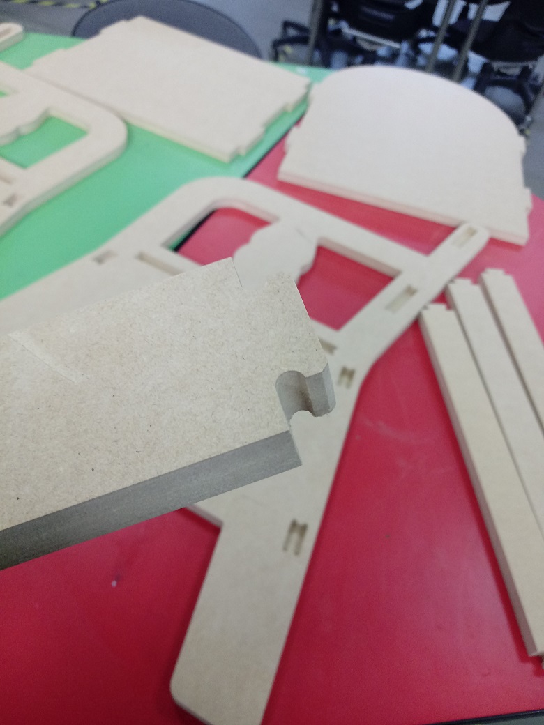
We can see the cutted parts, to assembly:
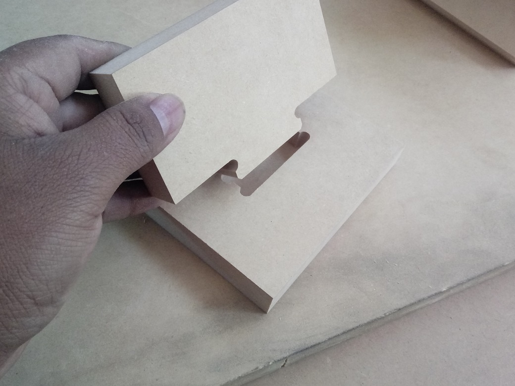
The assembly was successful, the method to assembly is good because the chamfer help to it:
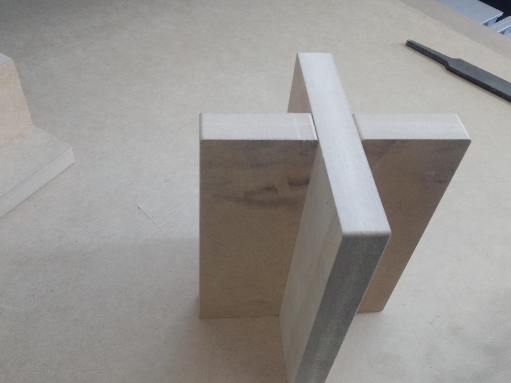
The junction of two same pieces, it has the same profile:
The junction is correct and successful:
INDIVIDUAL ASSIGNMENT
1. Designing a Confortable Chair
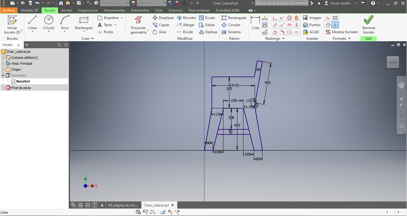
I design the base to chair, it is linear mode:
I extrude the design and add the hole to junction:
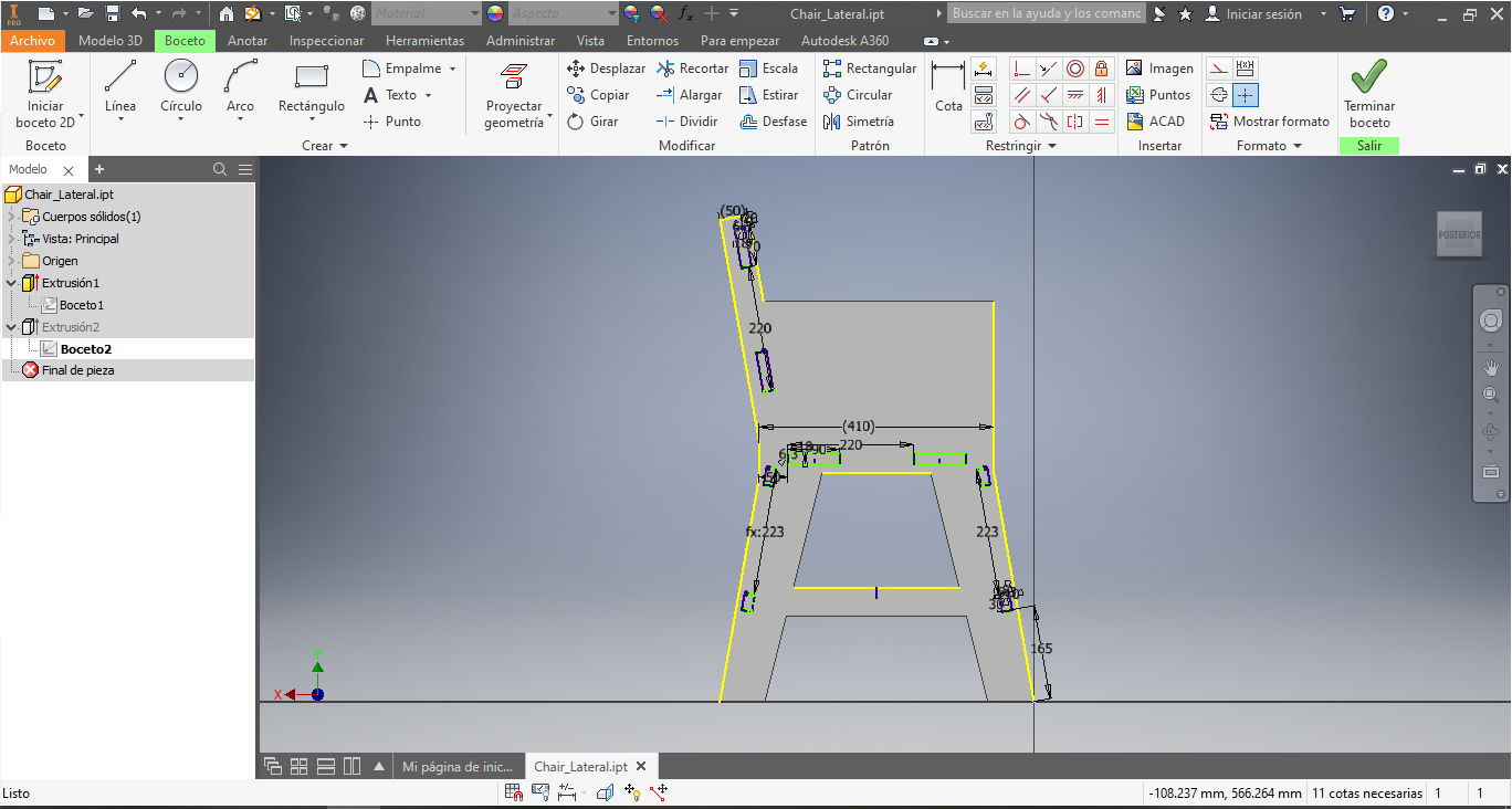
Afterwards, I did the chamfer and also I did the internal cutting:
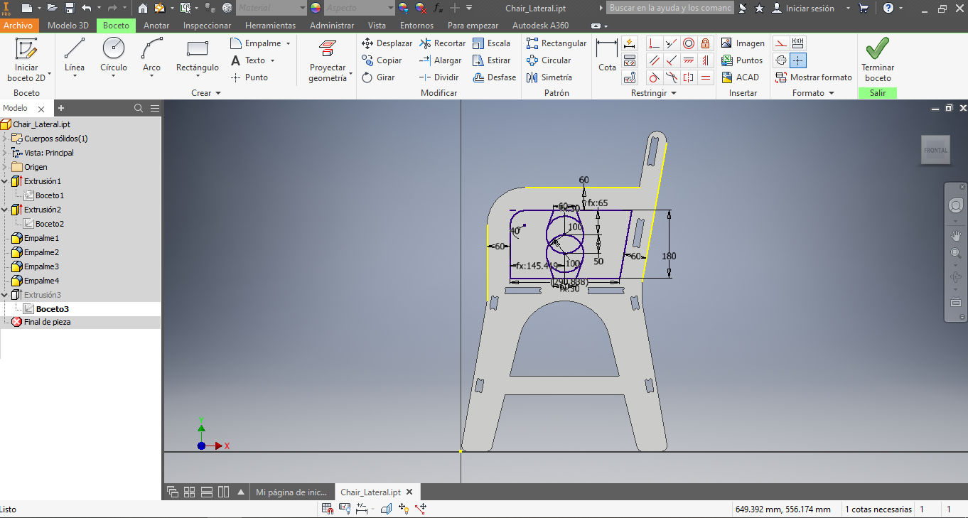
Finally, I did the chamfer to decorate the chair:
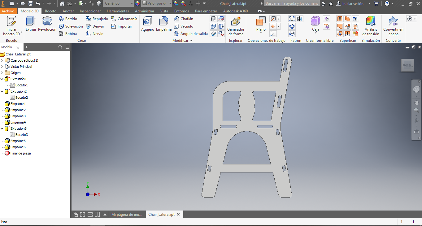
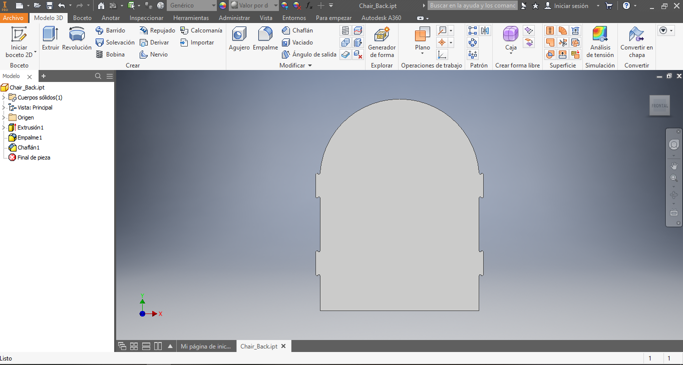
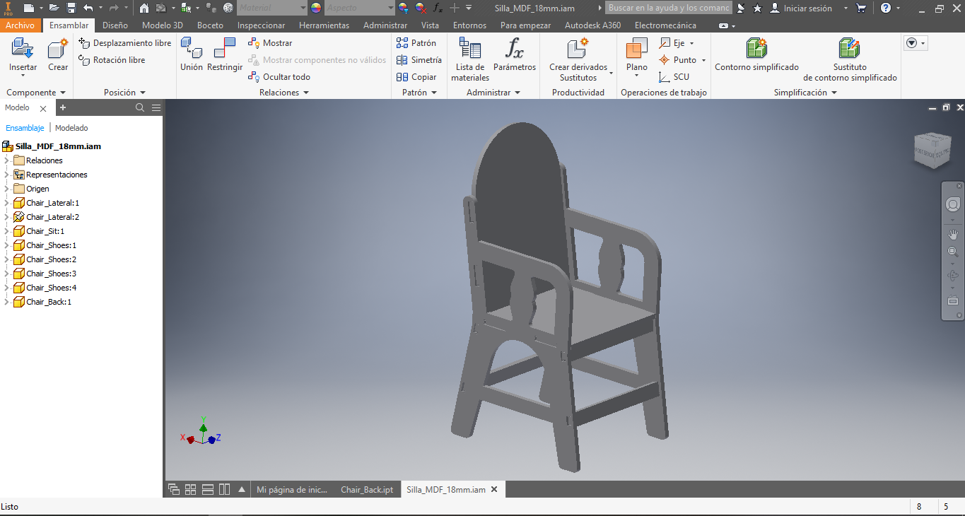
So I create the chair back:
Afterwards, I assembly the chair:
I create the DWG file from design:
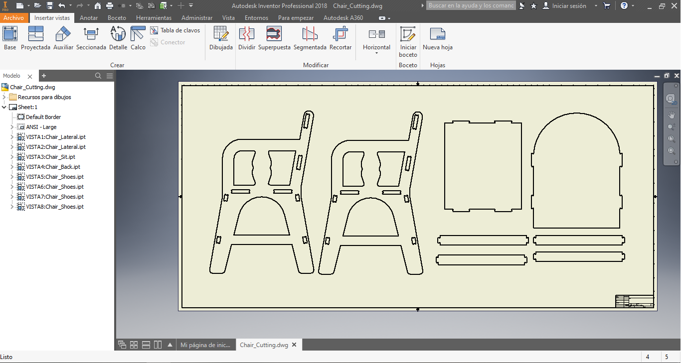
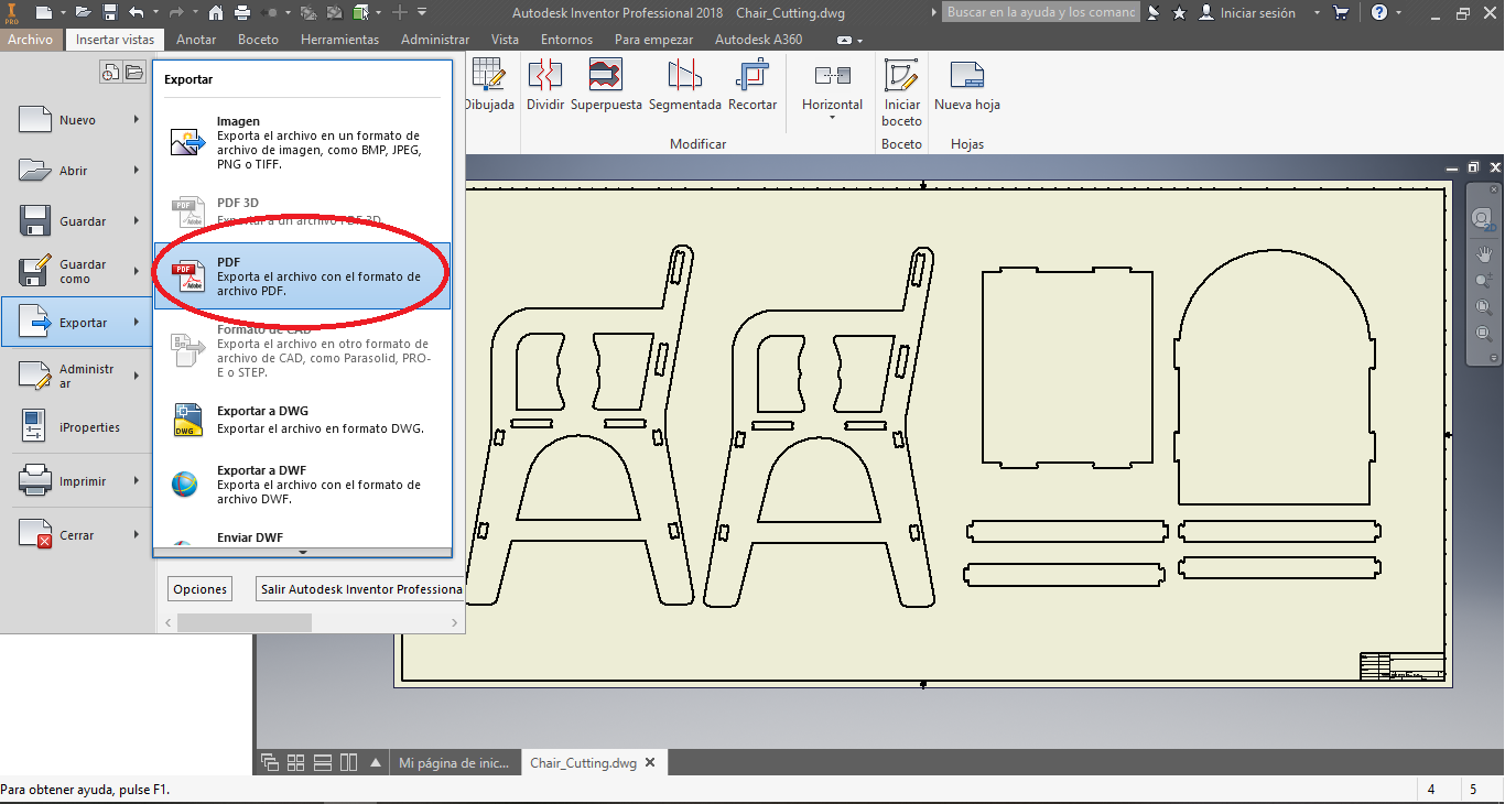
I export the PDF from DWG file:
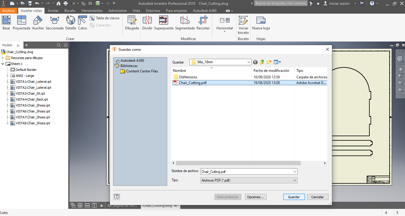
I save the PDF file to coherent name:
2. Preparing the Chair Design to Cut
To cut the design create a project and import the PDF file:
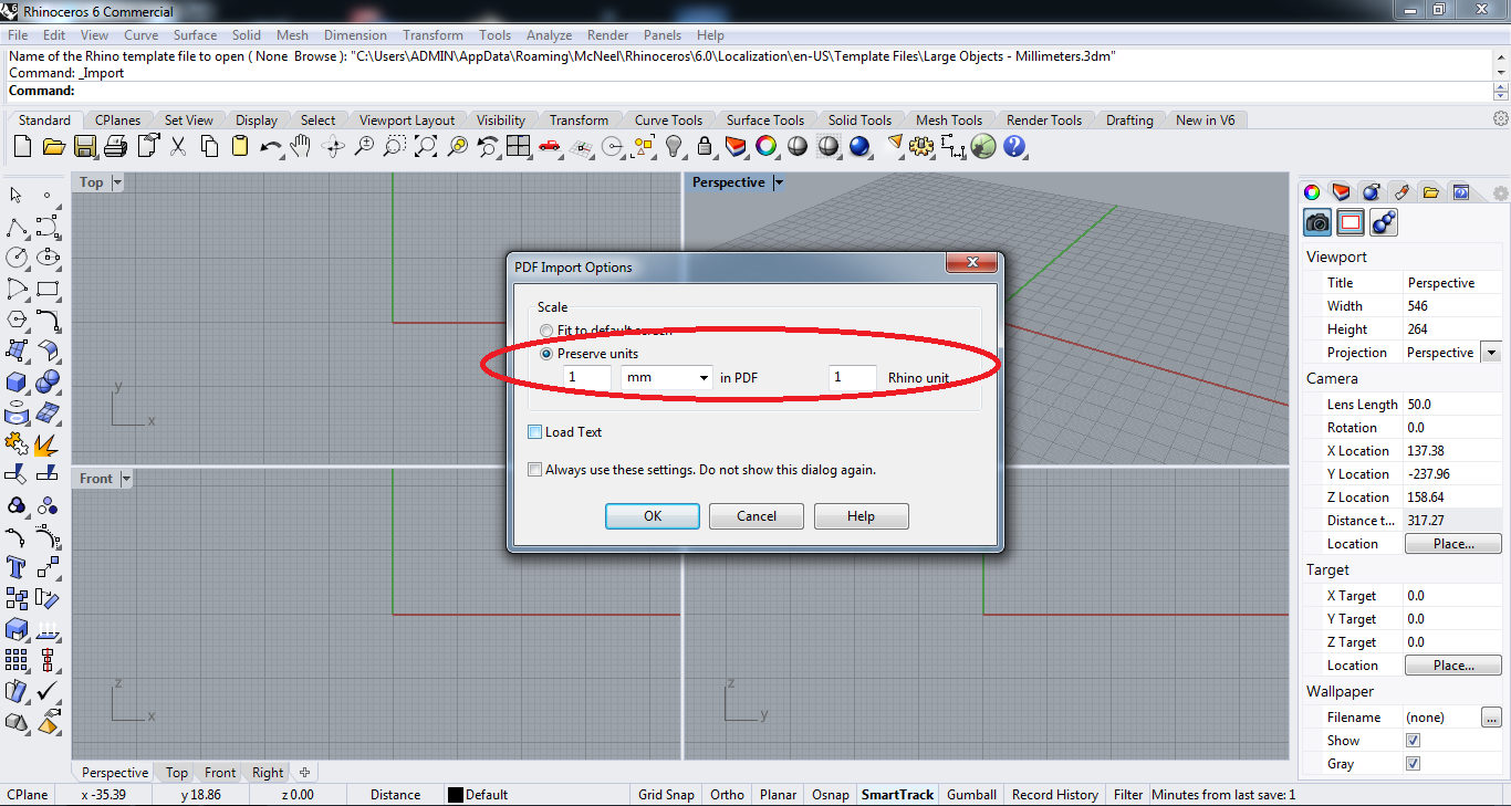
I am care to preserve the untis:
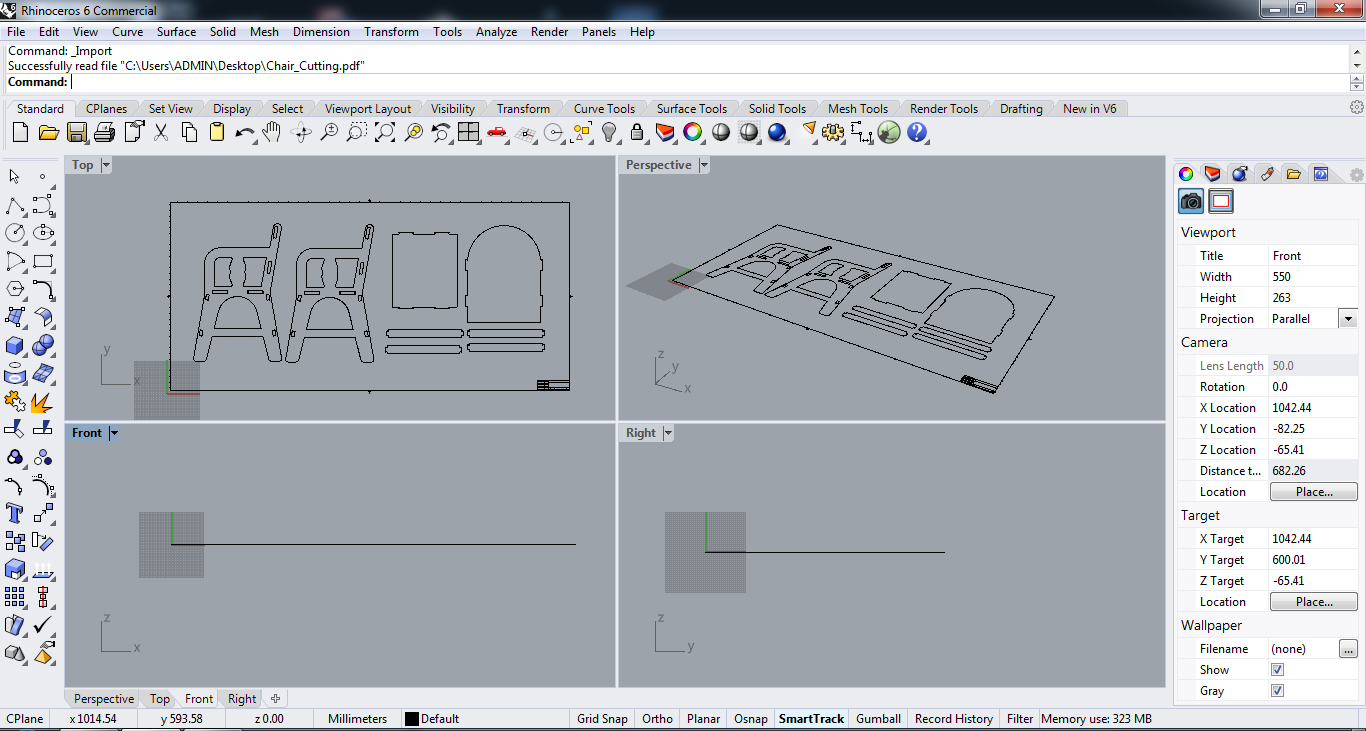
The design is import with all the parts:
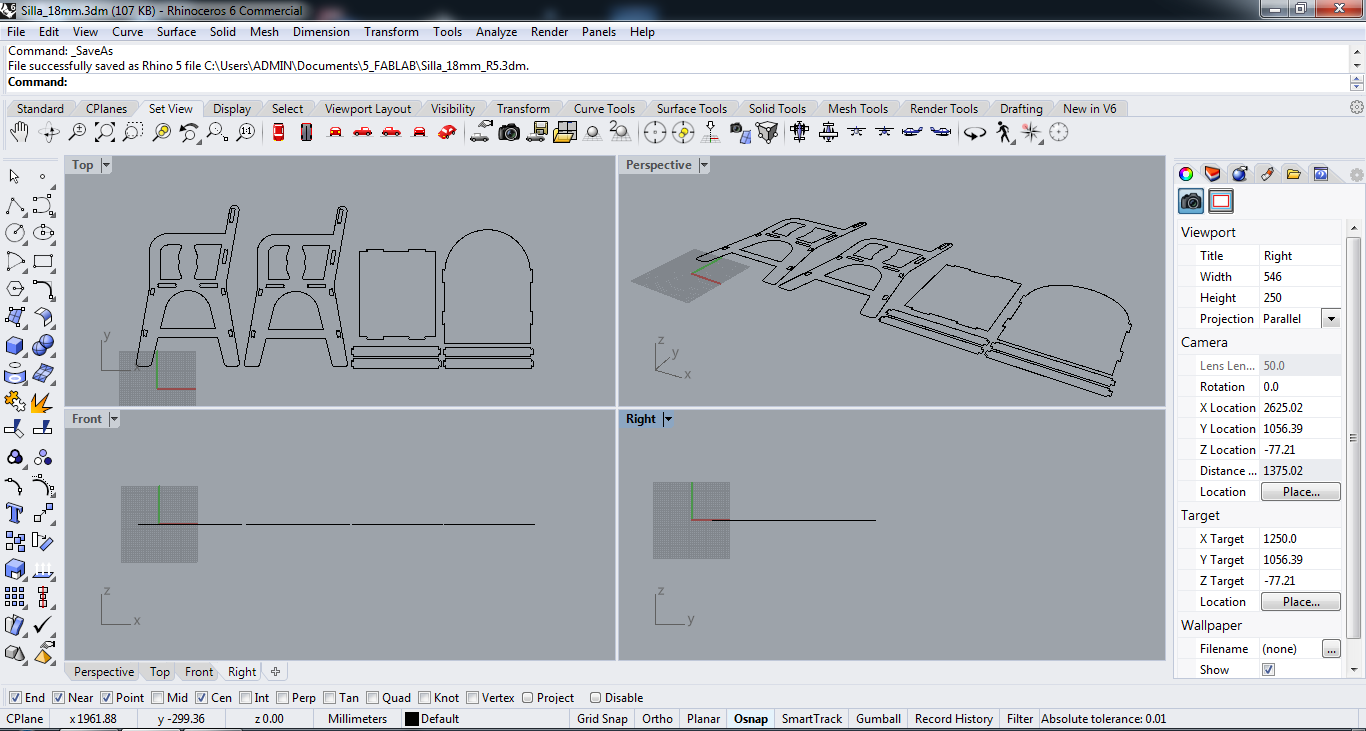
I erased the parts that are not important:
I add the frame to MDF board:
To start the configuration process, I press the Copy Model Bounding Box button and I add the H measure height:
I add the Coordinate System and check the option:
I add the Work Zero and check the option:
I start the cutting process for POCKETING:
I add the parameters to pocketing:
I start the cutting process for PROFILING for the internal cutting:
I add the parameters to internal profiling:
I start the cutting process for PROFILING for the external cutting:
I add the parameters to external profiling:
We have the three jobs, the boxs, the internal profiling and the external profiling:
- The boxs:
- The internal profiling:
- The external profiling:
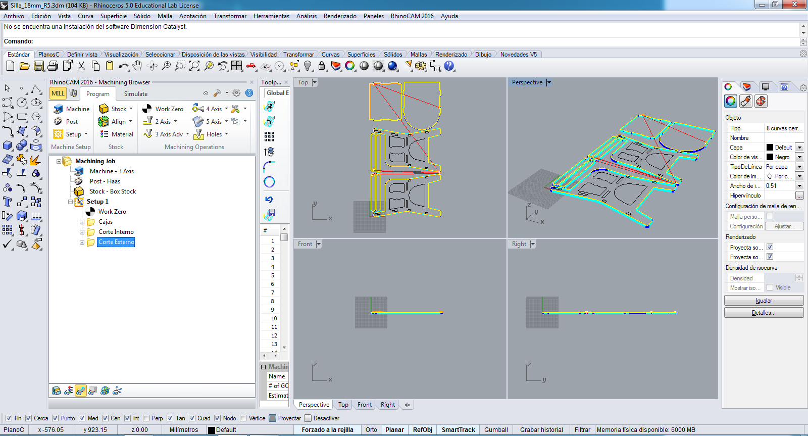
Afterwards, I post the NC file to convert the JG file, and the JG file must send to VG1325 machine to cut.
3. Cutting the Chair
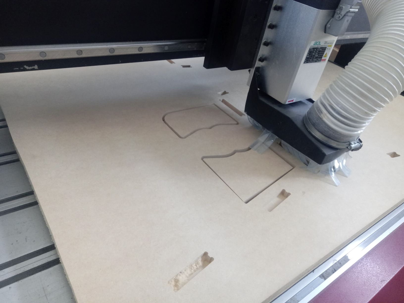
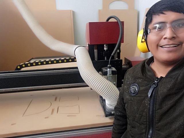
Then I start the process cutting in the VG1325 machine:
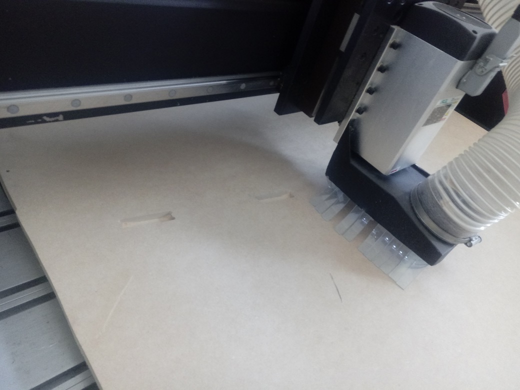
We can see the cutting process in the POCKETING and PROFILING
Smiling
We can see the cutting process in the POCKETING and PROFILING
We can see in video this process:
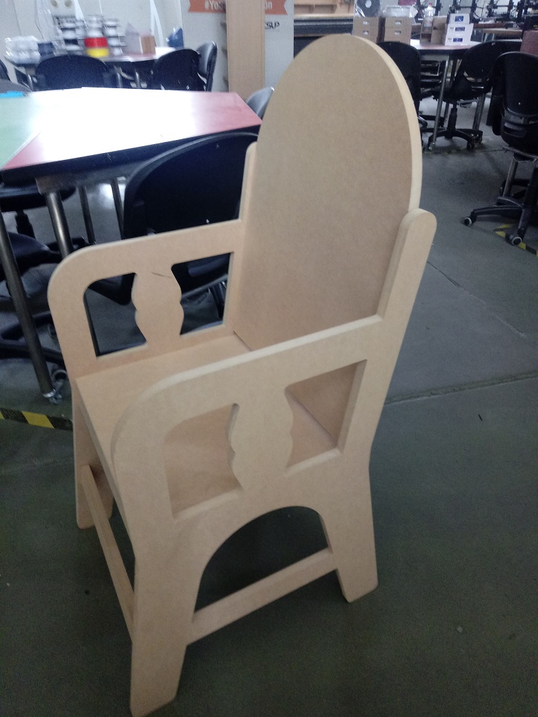
We can see all the parts of the chair:
4. Assembling the Chair
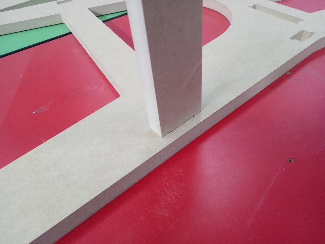
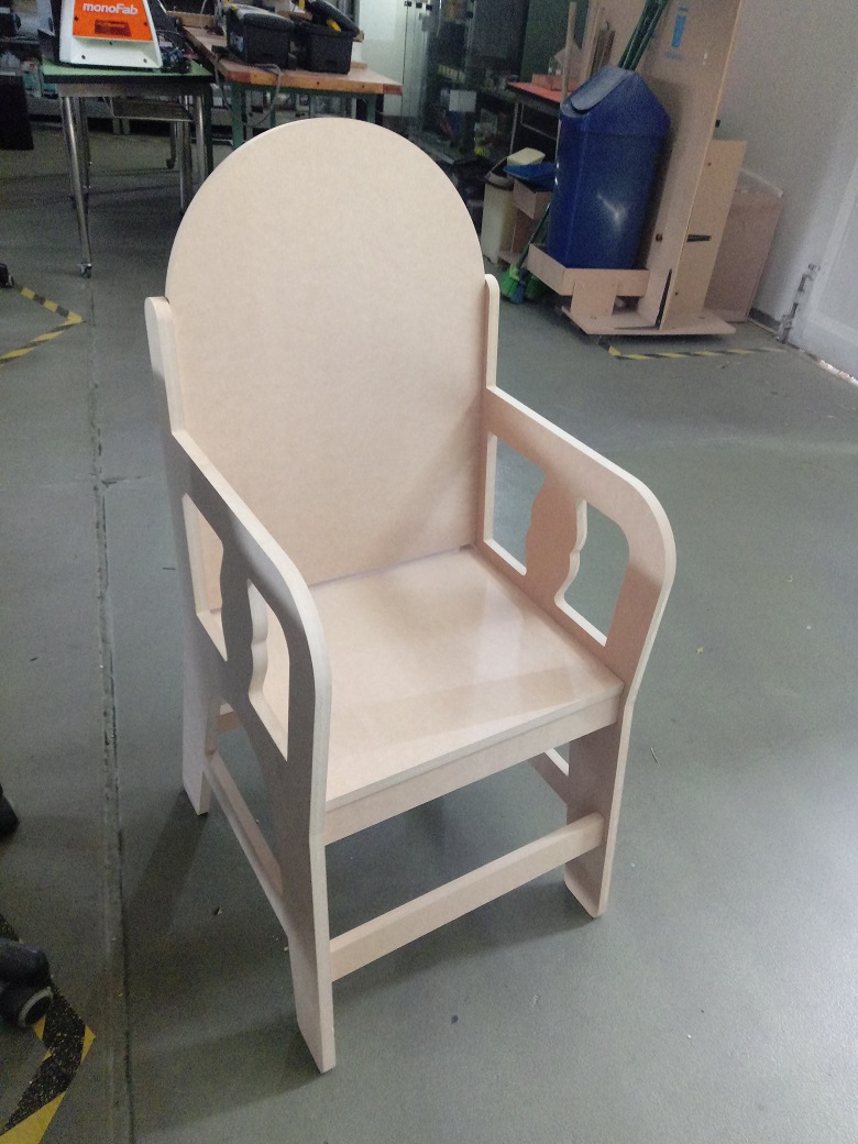
I start the assembling process, it is very easy because the cutting process was well:
The junction is well and the parts are assemblied well:
We can see the chair mounted on the right side
We can see the chair mounted on the left side
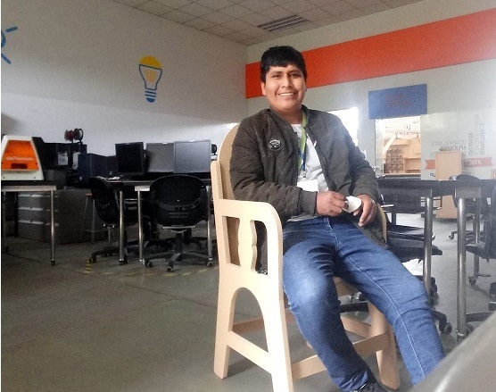
It is very confortable:
| Description | Files |
|---|---|
| Back Chair in Autodesk Inventor | Chair_Back.ipt |
| Side Chair in Autodesk Inventor | Chair_Lateral.ipt |
| Pose Shoes in Autodesk Inventor | Chair_Shoes.ipt |
| Sit Chair in Autodesk Inventor | Chair_Sit.ipt |
| Chair in PDF | Chair_Cutting.pdf |
| Junction in Autodesk Inventor | Junction_Test.ipt |
| Cross in Autodesk Inventor | Cross_Test.ipt |
| Pattern test in PDF | Cutting_Test.pdf |