7. Electronics Design
Group Project:
- Use the test equipment in your lab to observe the operation of a microcontroller circuit board
Individual Project:
- Redraw an echo hello-world board, add (at least) a button and LED (with current-limiting resistor) check the design rules, make it, and test it
- Extra credit: simulate its operation
GROUP ASSIGNMENT
This week I worked on design a board to test microcontroller with equiment in our Lab. I use the test equipment in my lab to observe the operation of a microcontroller circuit board.
1. Testing the operation of a microcontroller
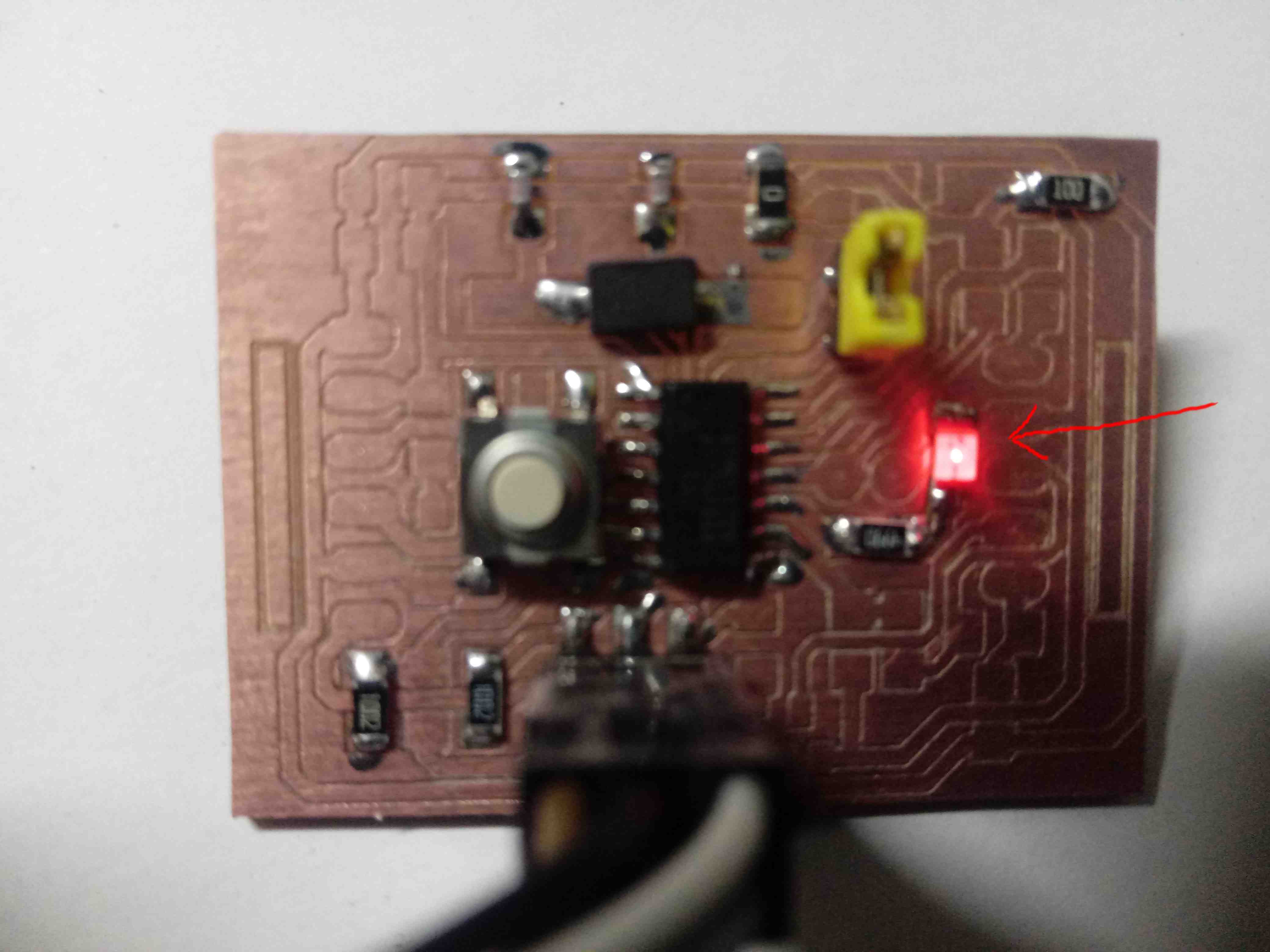
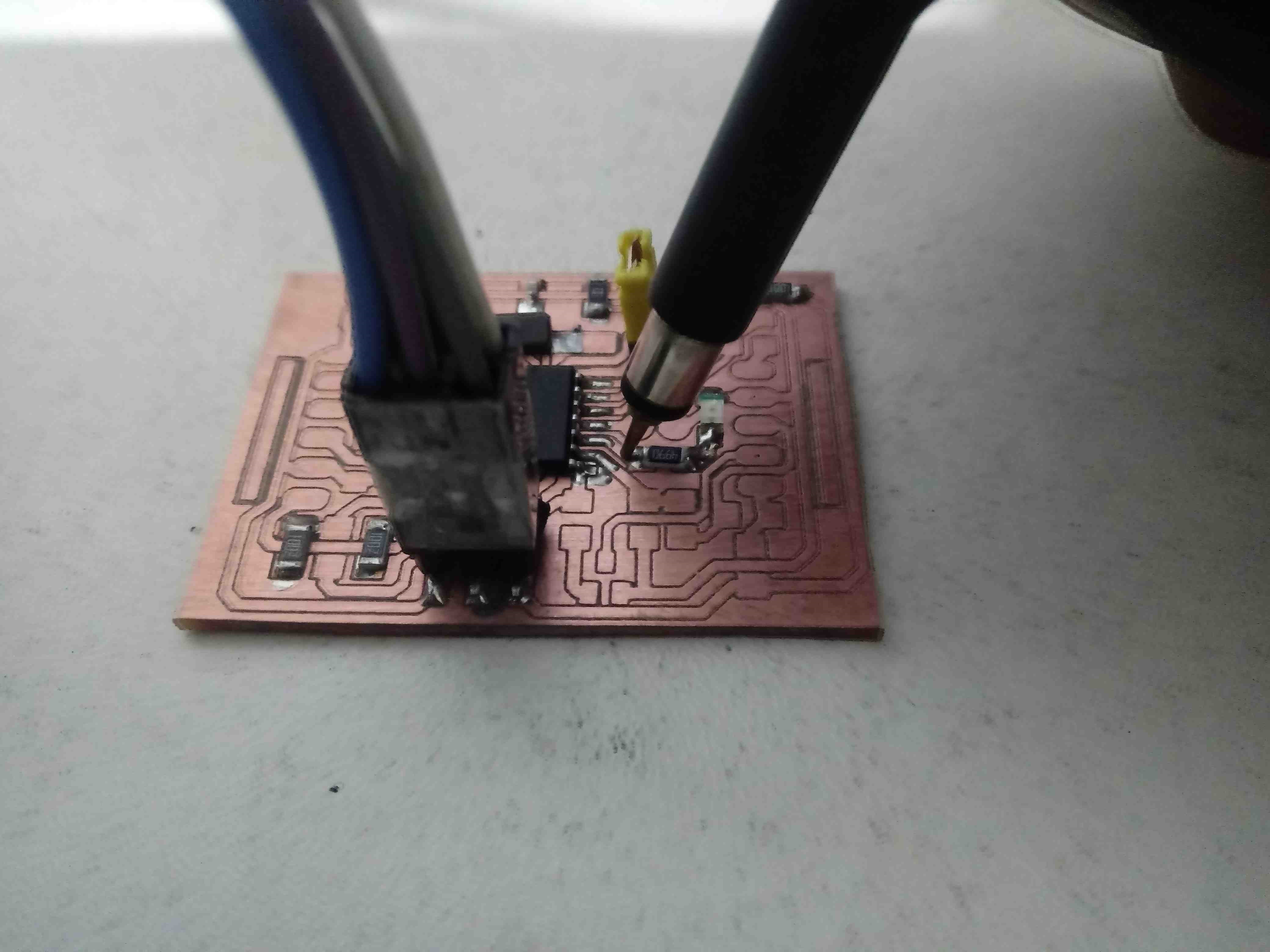
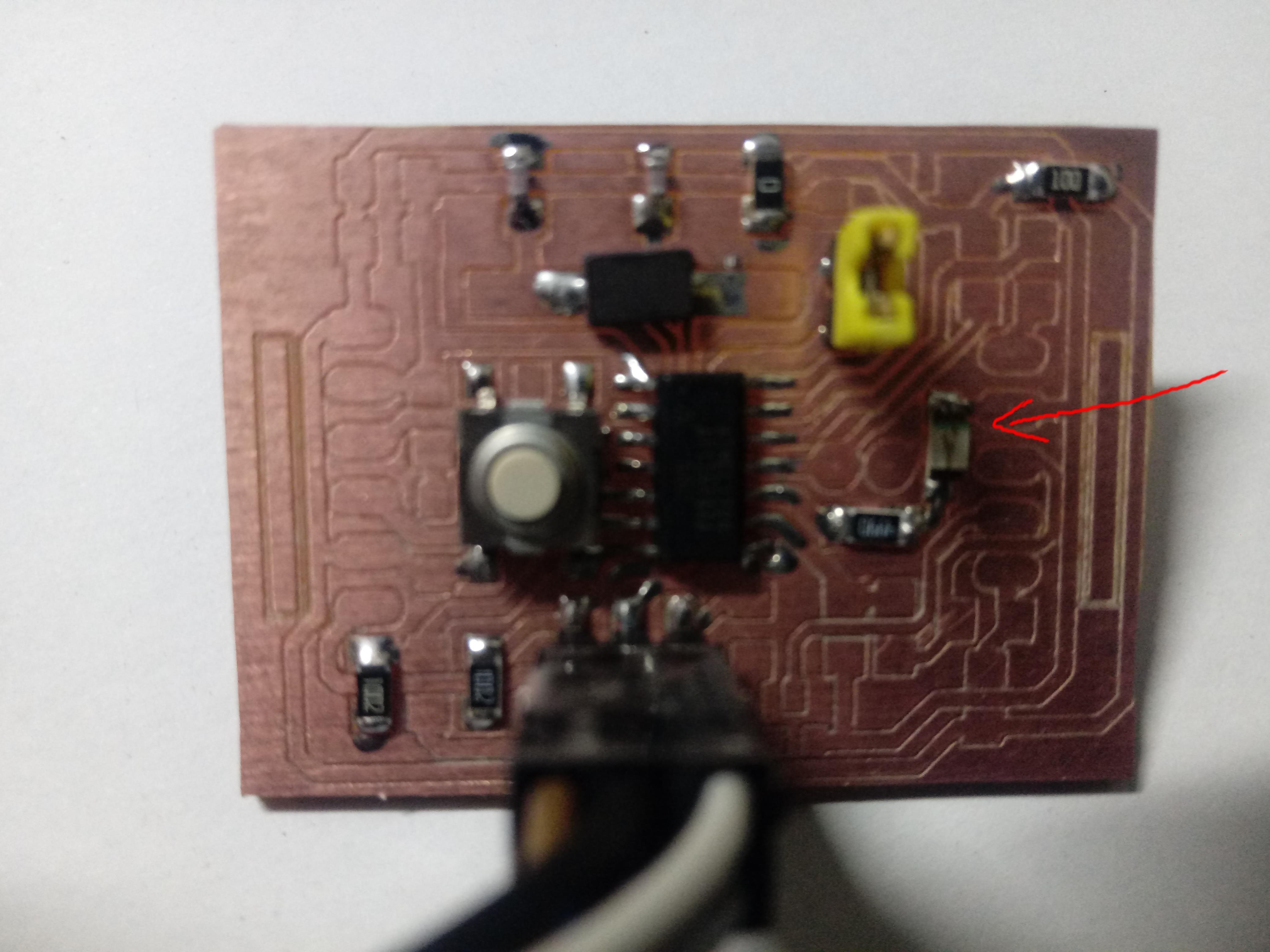
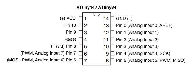
I use the ATTINY44A microcontroller, I probe the 10 pin of the microcontroller, it is programmed with the blink led with the pin 10, also it has a led in this pin.
We see in this test the state is LOW or led off.

We see in this test the state is HIGH or led on.
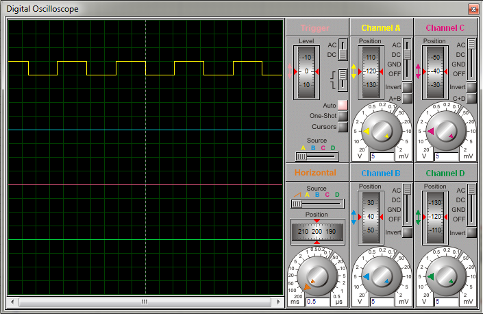
Also We test with a oscilloscope in the same pin 10.
We see a signal with the following features:
| Item | Feature | Measure | Theory |
|---|---|---|---|
| 1 | Frecuency | 0.46296 Hz | 0.5 Hz |
| 2 | Period | 2.16 seg | 2 seg |
| 3 | Voltage | 0V / 5V | 0V / 5V |
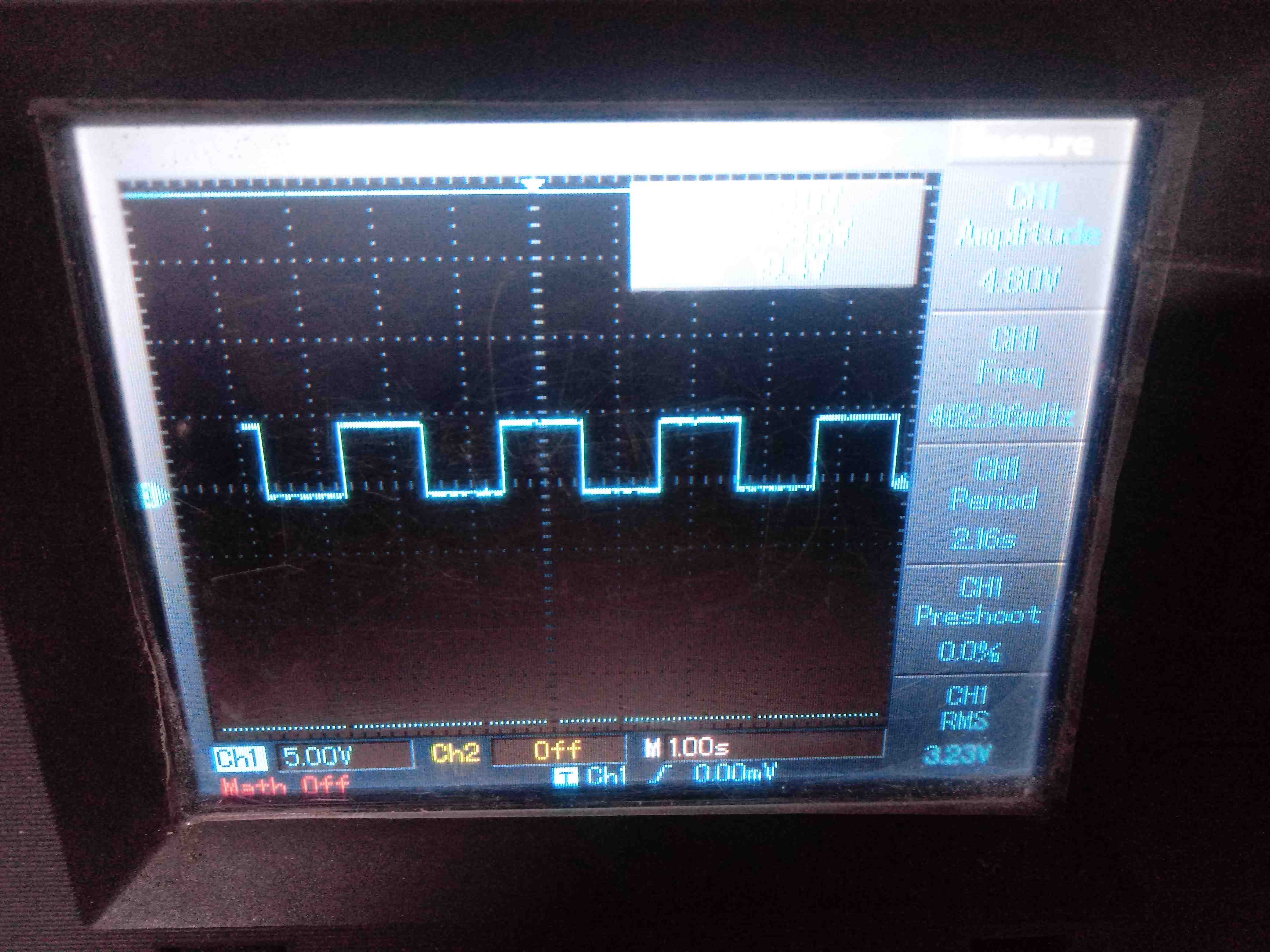
Then I can conclude that the program “Hello world” does not work exact with the time not correct, because the compiler works with approximation.
INDIVIDUAL ASSIGNMENT
- Redraw an echo hello-world board,
- Add (at least) a button and LED (with current-limiting resistor)
- Check the design rules, make it, and test it
- Extra credit: Simulate its Operation
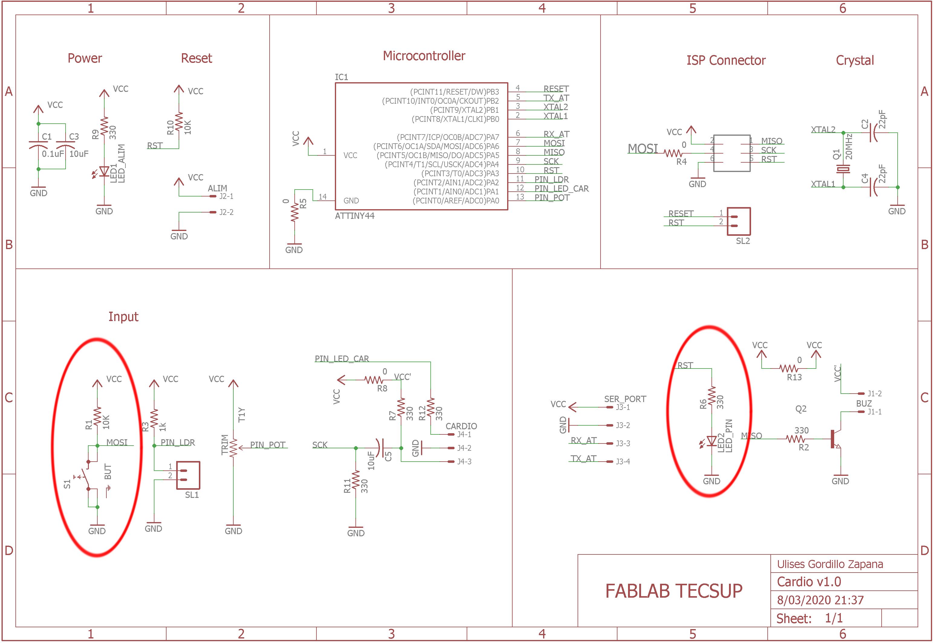
1. Redraw an echo hello-world board
To design the printed circuit board or PCB we use Autodesl Eagle software:

The schematic has the principal part to work with sensor an actuator:
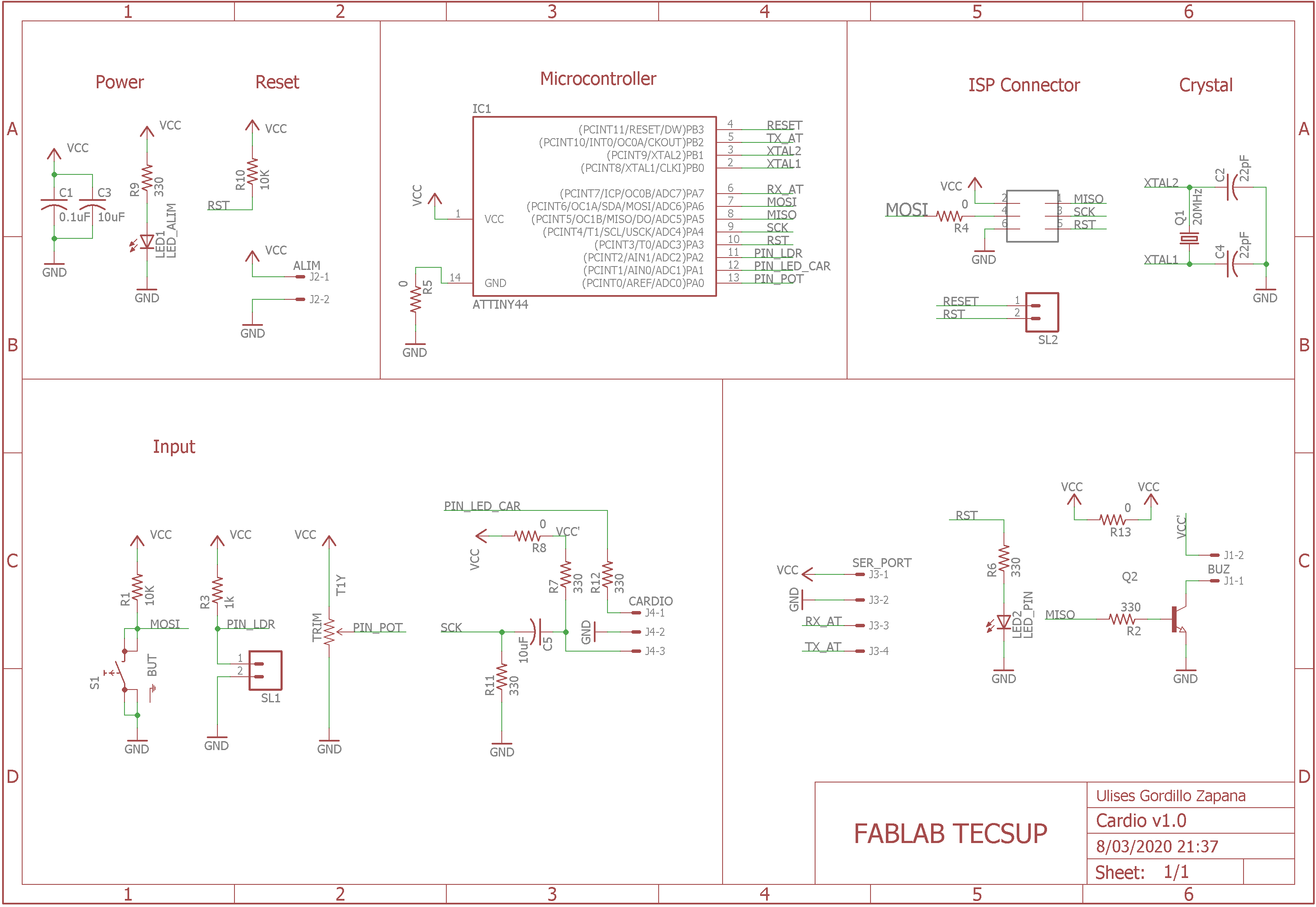
2. Add button and LED
The necessary part in the board is a button and a led:
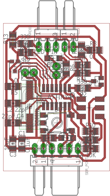
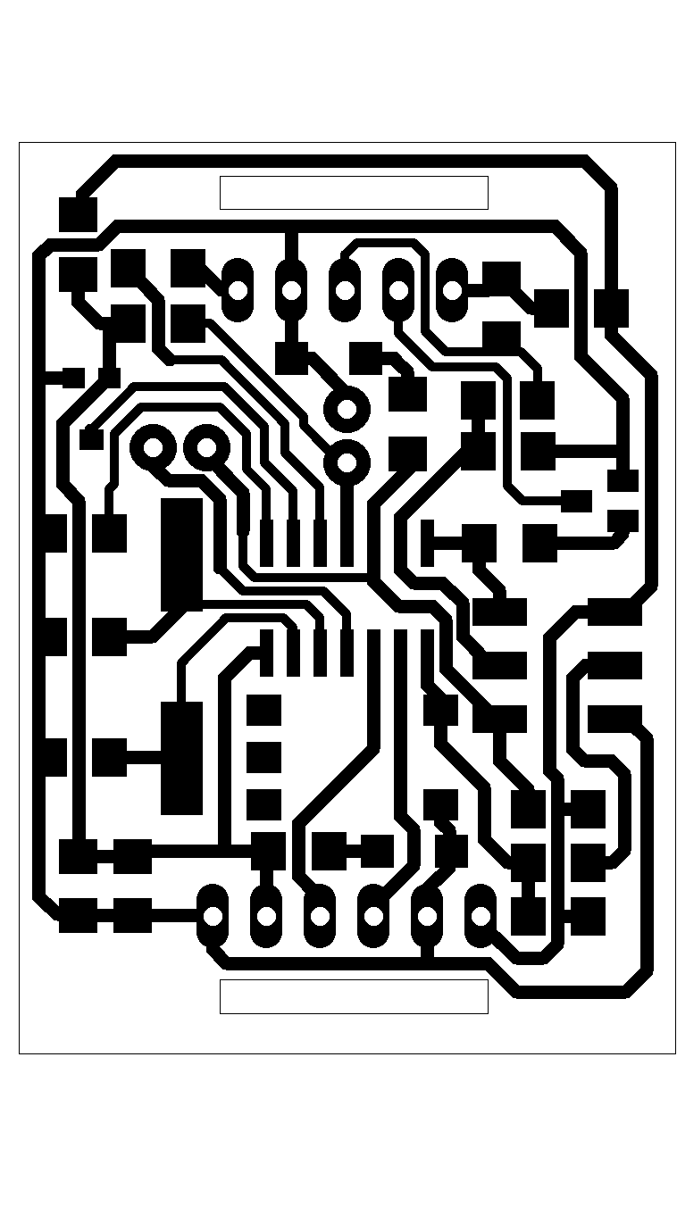
3. Designing with rules and making the board
The layout of the printed circuit board or PCB is shown in the following video:
4. Fabricating the board
I design the board with the correct rules and only the bottom layer:
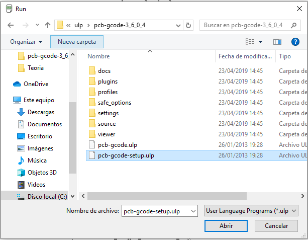
Setup the strategy gcode of milling machine:
I choose the correct layers:
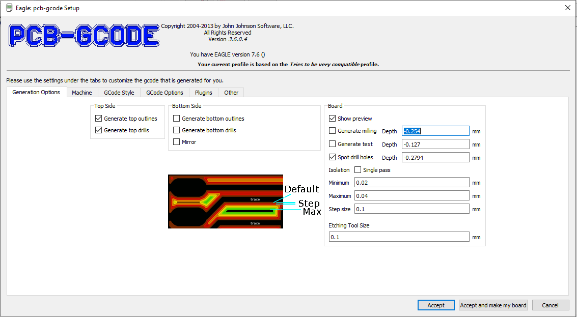
I choose the parameters of the machine.
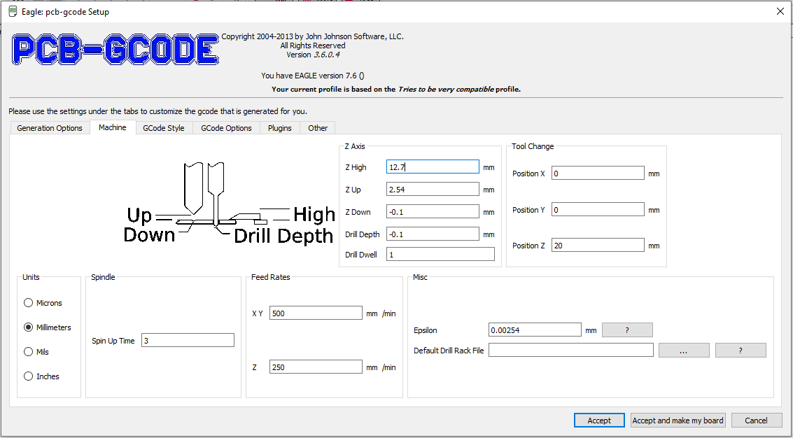
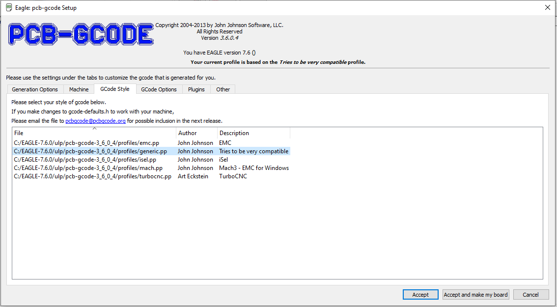
I check the machine with Generic type.
I check the correct file to creation:
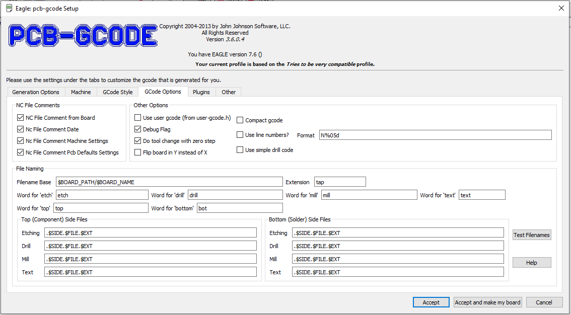
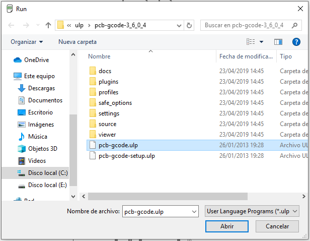
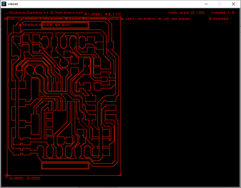
Then, I create the gcode file:
We can see the image of work:
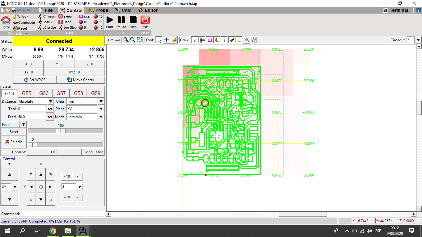
Open the gcode file in bCNC software to work with the CNC with grbl firmware:
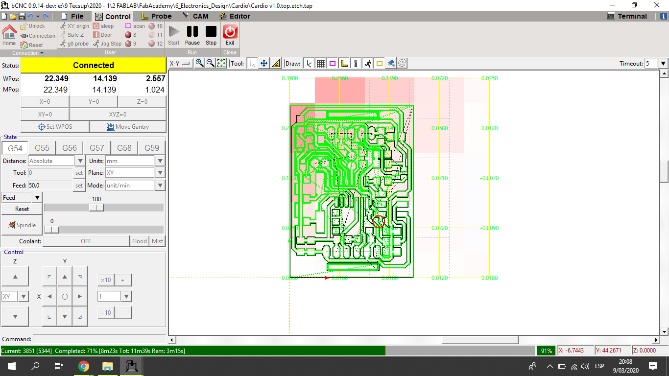
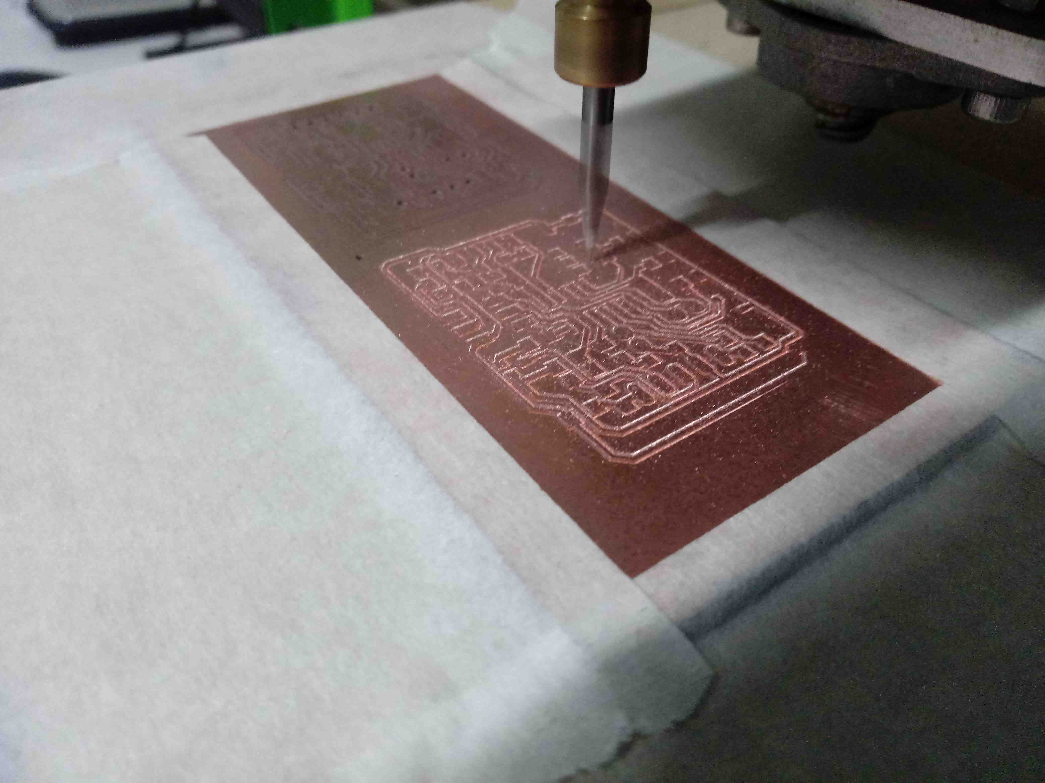
We can see the fabrication on process:
The router fabricates the board.
Finally I soldered the electronic components on the PCB board.
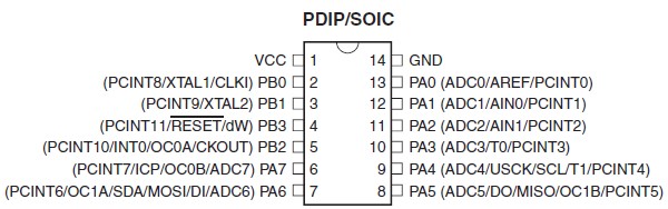
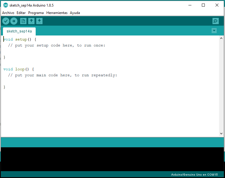
Also I check the pinout of the Attiny44A in Arduino IDE to proagram:
5. Testing it
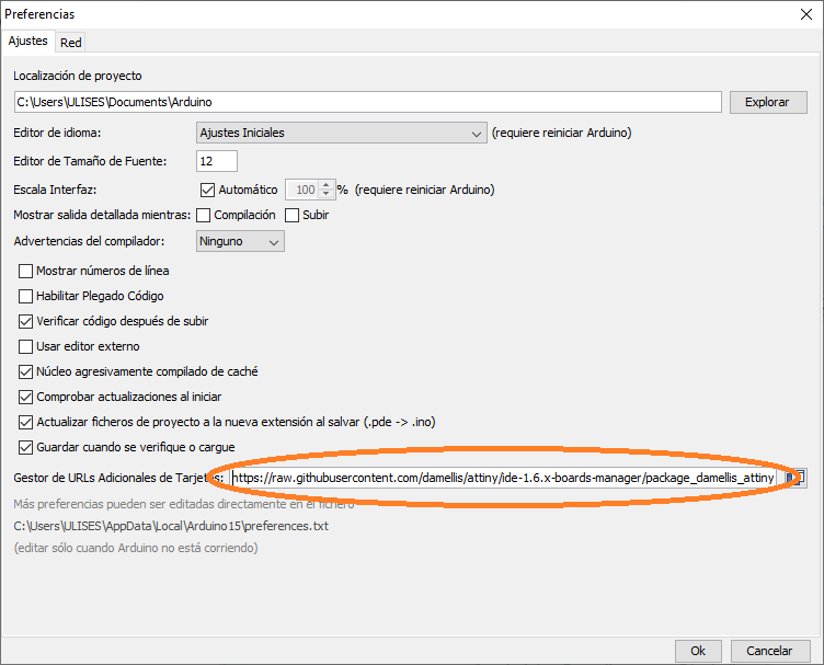
Configure the address to download the files to Attiny44A, this files compile in Arduino to Attiny44A:
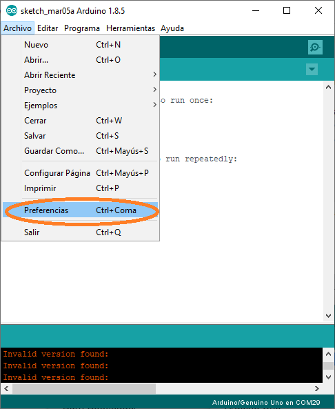
Copy and paste the address to download:
Also in Preferences check the View output: Compilation and Load
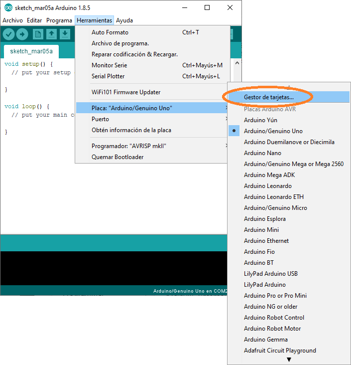
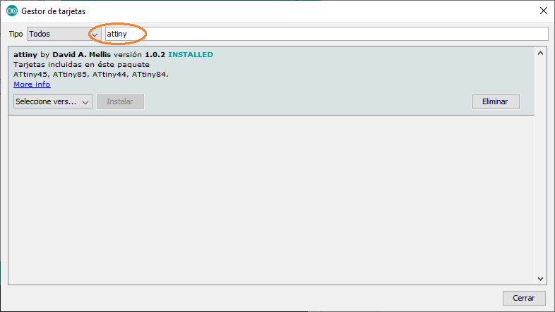
Install the libraries to compile the Attiny44 in ARDUINO IDE:
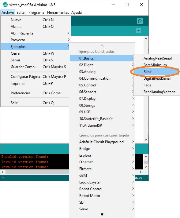
Now load the “Hello world” program to Attiny44A, open the Arduino and search in File/Examples/01.Basics/Blink
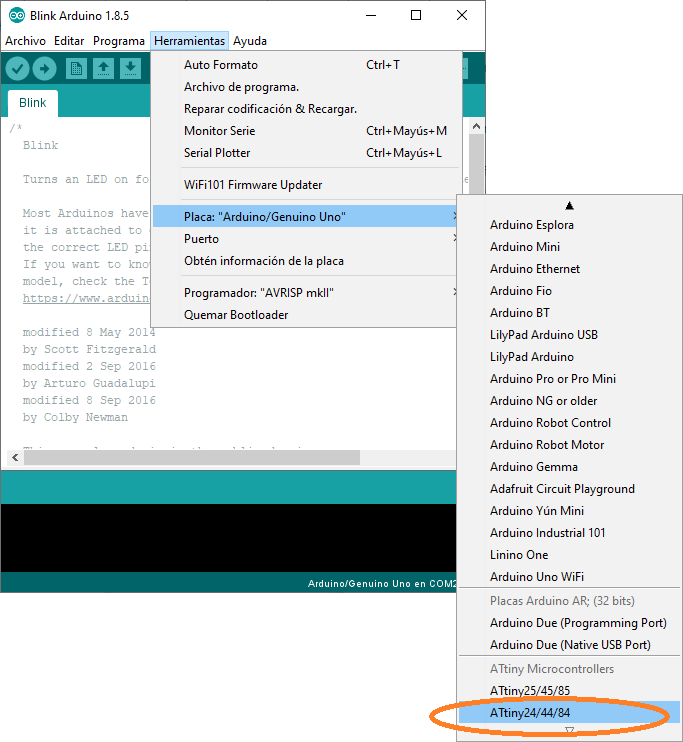
I choose the Attiny44 in board option in Arduino IDE
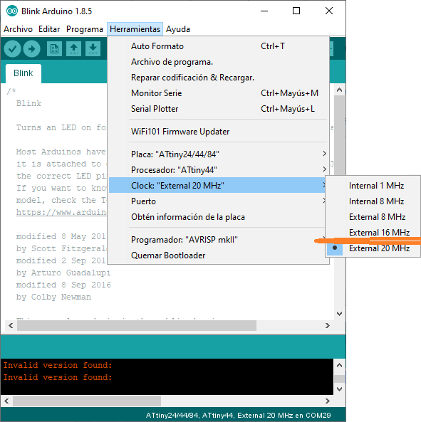
I choose in PROCESSOR the Attiny44 and CLOCK the external 20MHz
I connect the USBtiny and the created PCB Board
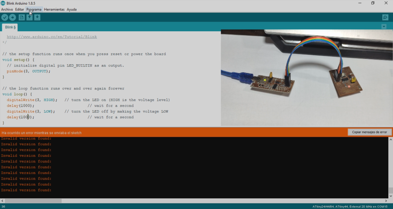
We can see a video demostration:
6. Simulate its Operation
First I changed the program to simulate:
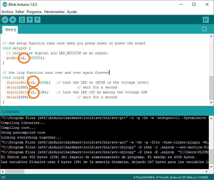
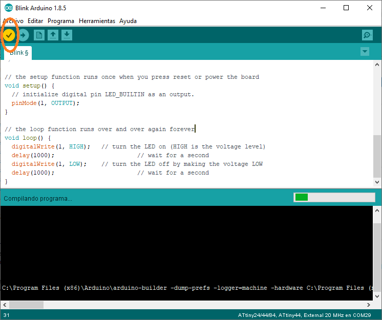
Afterwards I compiled the program in Arduino IDE:
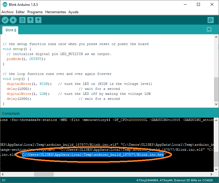
Afterwards I copied the HEX file path to the simulate:
In this case I simulate the functionality of the “Hello Wold” in Proteus Software from Labcenters Electronics
I colocate a Digital Oscilloscope in the schematic to view the output signal
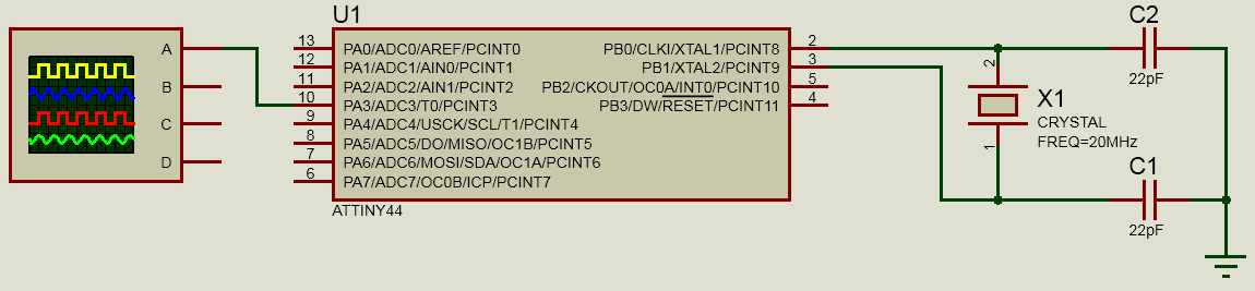
Configurate the HEX file in Attiny44A to simulate over Proteus.
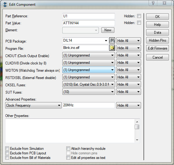
Proteus shows the simulated signal:
Designed Files
| Description | Files |
|---|---|
| Eagle Schematic | Cardio_v1.0.sch |
| Eagle Board | Cardio_v1.0.brd |
| Image Board | Cardio_v1.0.png |
| Blink Arduino | Blink.ino |
| Hex File | Blink.hex |
| Proteus File | Simulation_Attiny44A.pdsprj |