10. Input Device
Individual Assignment:
- Measure something: add a sensor to a microcontroller board that you have designed and read it
Group Assignment:
- Probe an input device’s analog levels and digital signals
INDIVIDUAL ASSIGNMENT
This week I worked on probing sensor in the ATTINY44A C++ Native over Atmel Studio.
1. Analog Sensor and Digital
The schematic has the principal part to work with sensor an actuator:
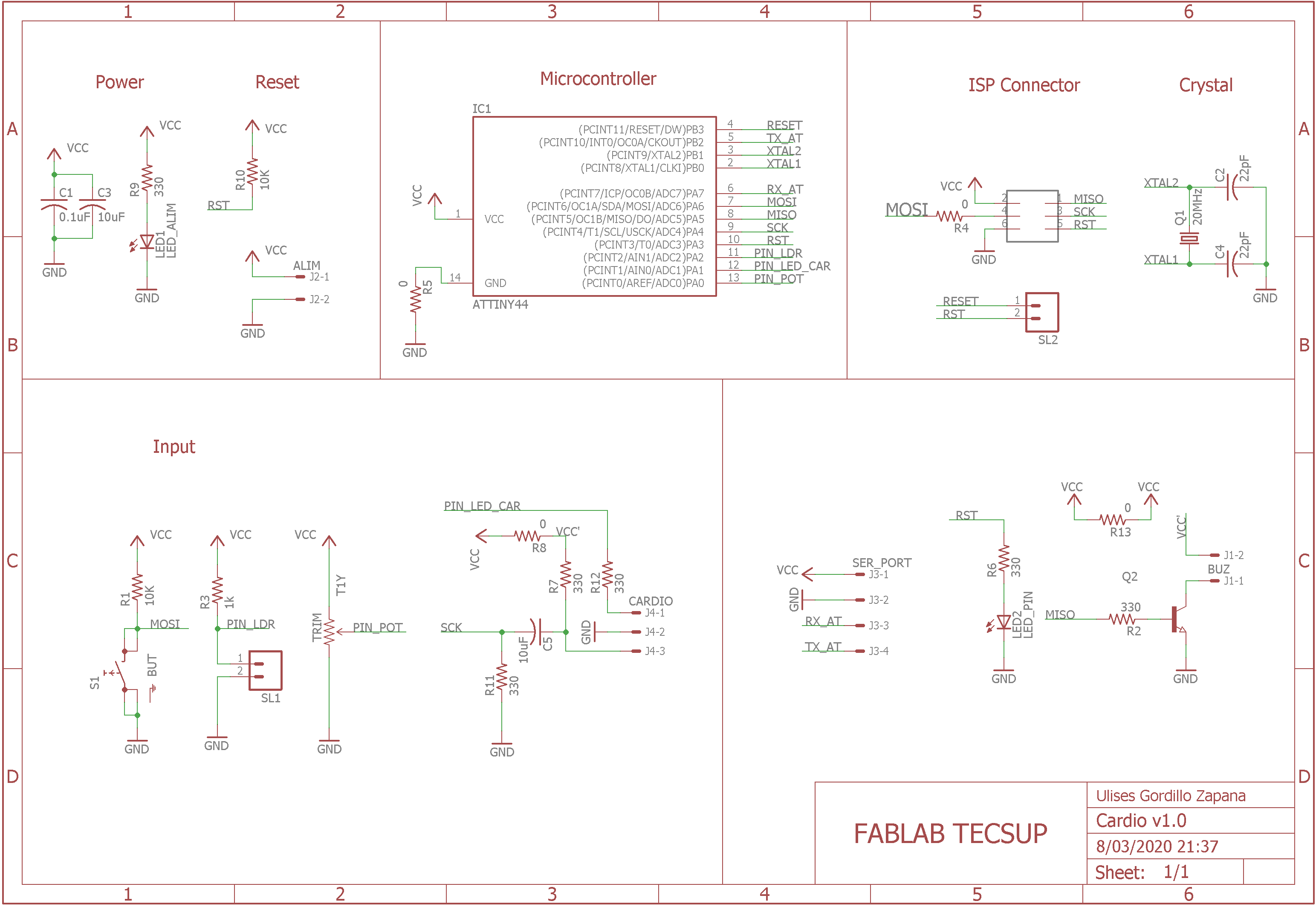
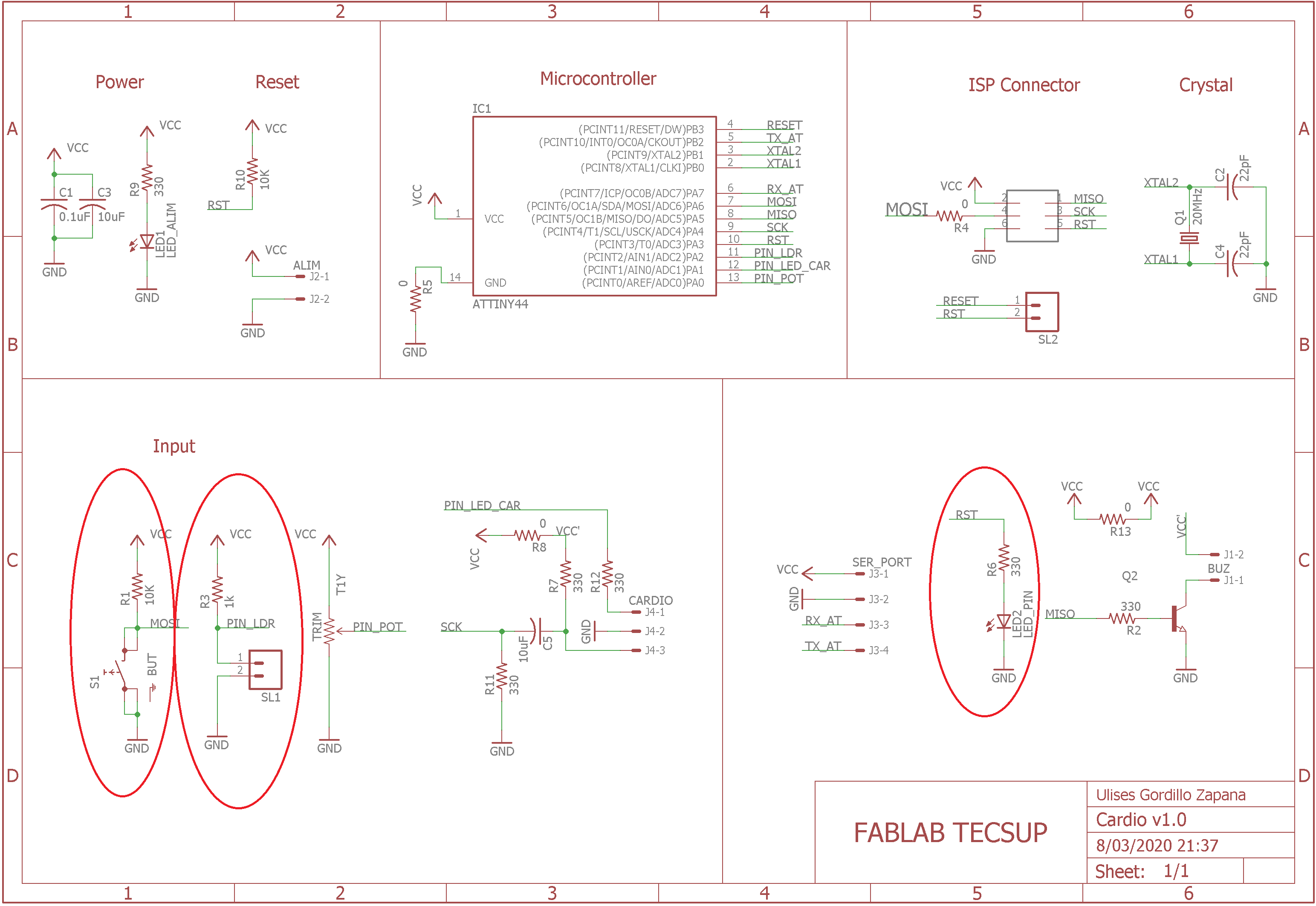
We choose to work with the LDR in ANALOG INPUT and the BUTTON in DIGITAL INPUT, and we need a actuator as LED:
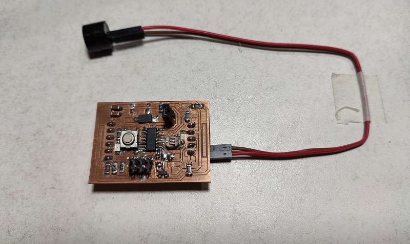
This board was fabricated in WEEK 7: Electronics Design:
We can see the Sensors and Actuators:
- Buzzer in PIN PA1
- LDR in PIN PA2
- LED in PIN PA3
- Button in PIN PA6
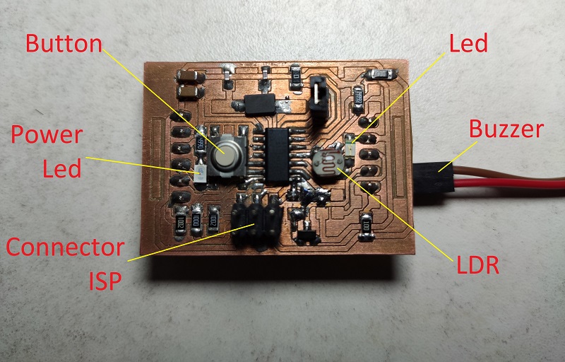
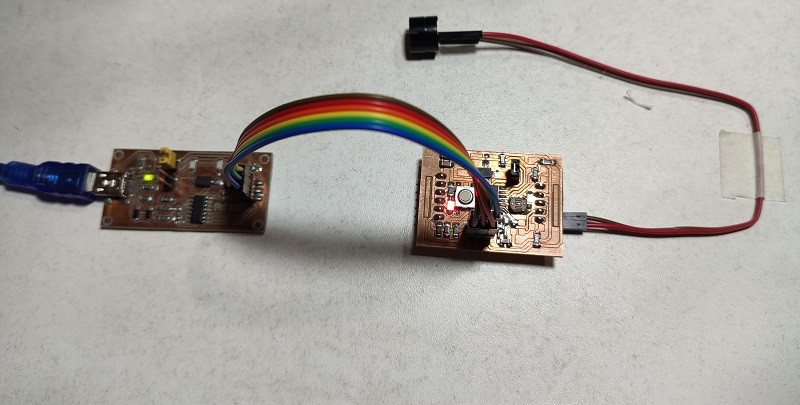
We can see connect to USBTinyISP this board was fabricated in WEEK 7: Electronics Production:
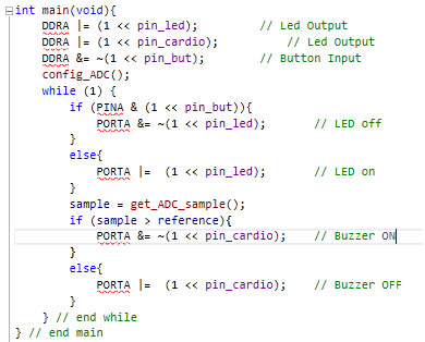
Now we program with the program which:
- The button control the LED
- The LDR signal turn ON or turn OFF the Buzzer
2. Project with IR Sensor and Attiny44
In this project I use the infrared sensors to measure the distance of the objects in this case I will activate them with my fingers:
The infrared sensor has an infrared emitting led and a phototransistor to detect the rebound of said infrared signal.
For this purpose we have the following program:
//****************************************************
// Ulises Gordillo Zapana - FabAcademy 2020
//****************************************************
#define pin_tx      8
#define pin_rx      7
#define pin_but     6
#define pin_buz     5
#define pin_cardio  4
#define pin_led     3
#define pin_ldr     A2
#define pin_led_car 1
#define pin_pot     0

// Function SETUP
void setup() {
  pinMode(pin_tx,INPUT);
  pinMode(pin_rx,INPUT);
  pinMode(pin_cardio,OUTPUT);
}

// Function LOOP
void loop(){
  if (!digitalRead(pin_rx)){
    digitalWrite(pin_cardio,HIGH);
    delayMicroseconds(1500);
    digitalWrite(pin_cardio,LOW);
    delayMicroseconds(1500);
  }
  else if (!digitalRead(pin_tx)){
    digitalWrite(pin_cardio,HIGH);
    delayMicroseconds(1000);
    digitalWrite(pin_cardio,LOW);
    delayMicroseconds(1000);
  }
  else{
    digitalWrite(pin_cardio,HIGH);
  }
}
We can see how it works in the following video:
GROUP ASSIGNMENT
- Probe an input device’s analog levels and digital signals
1. Probing the Analog and Digital Sensor
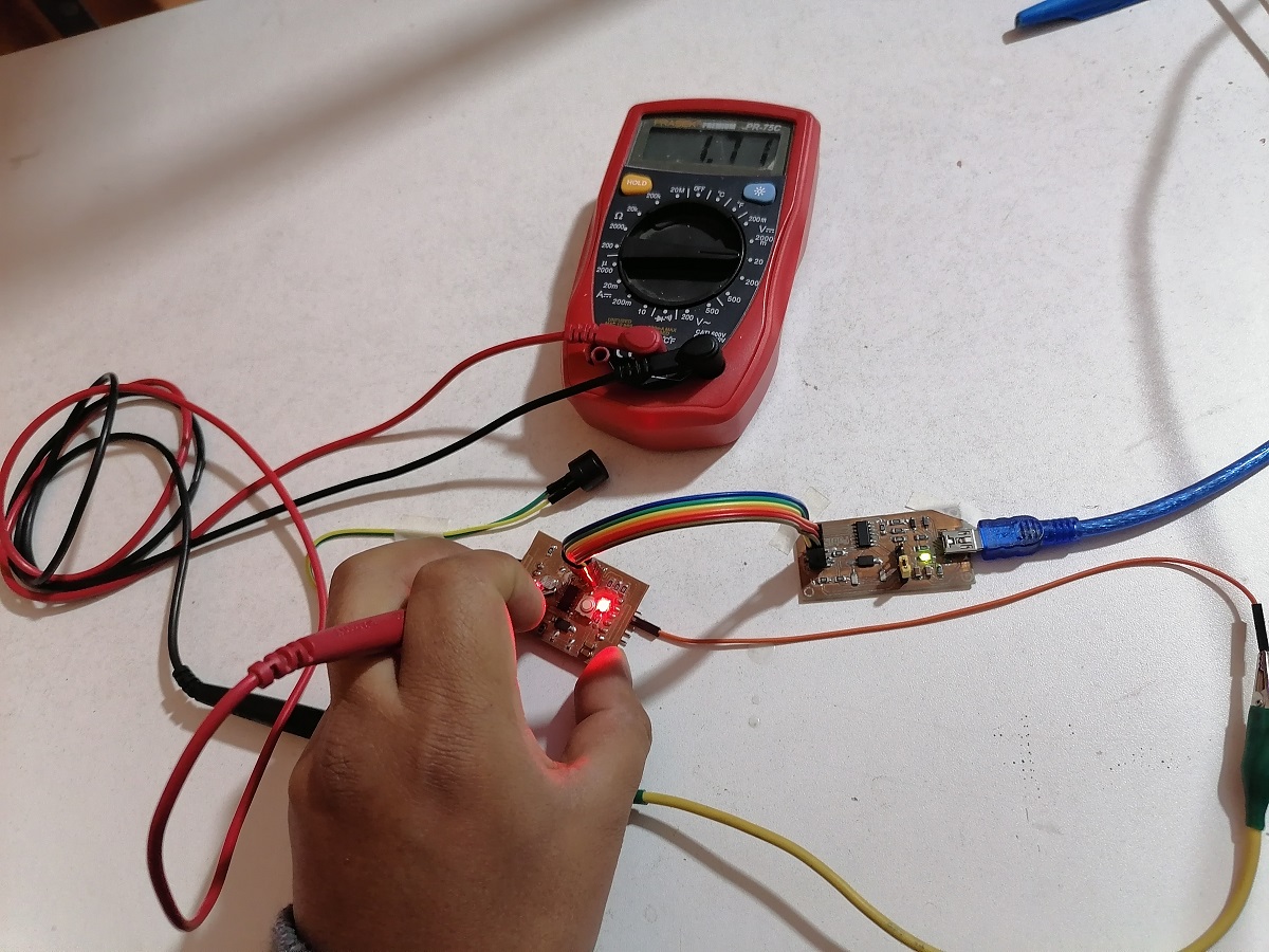
2. Measuring the LDR Voltaje
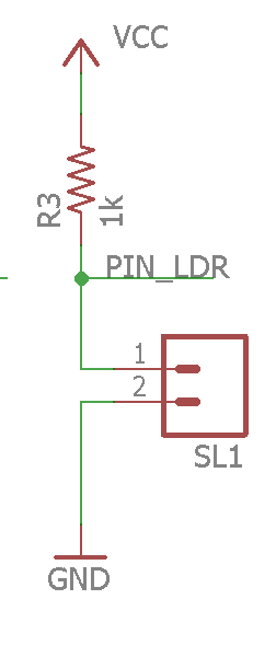
An LDR is an electronic device that varies its internal resistance in proportion to the amount of light that falls on its surface. The circuit that makes it work is the one shown:
The work of this circuit is proportional an analog signal in the central connection of the components
When the incidence of light is low, the voltage averages 3.03 Volts.
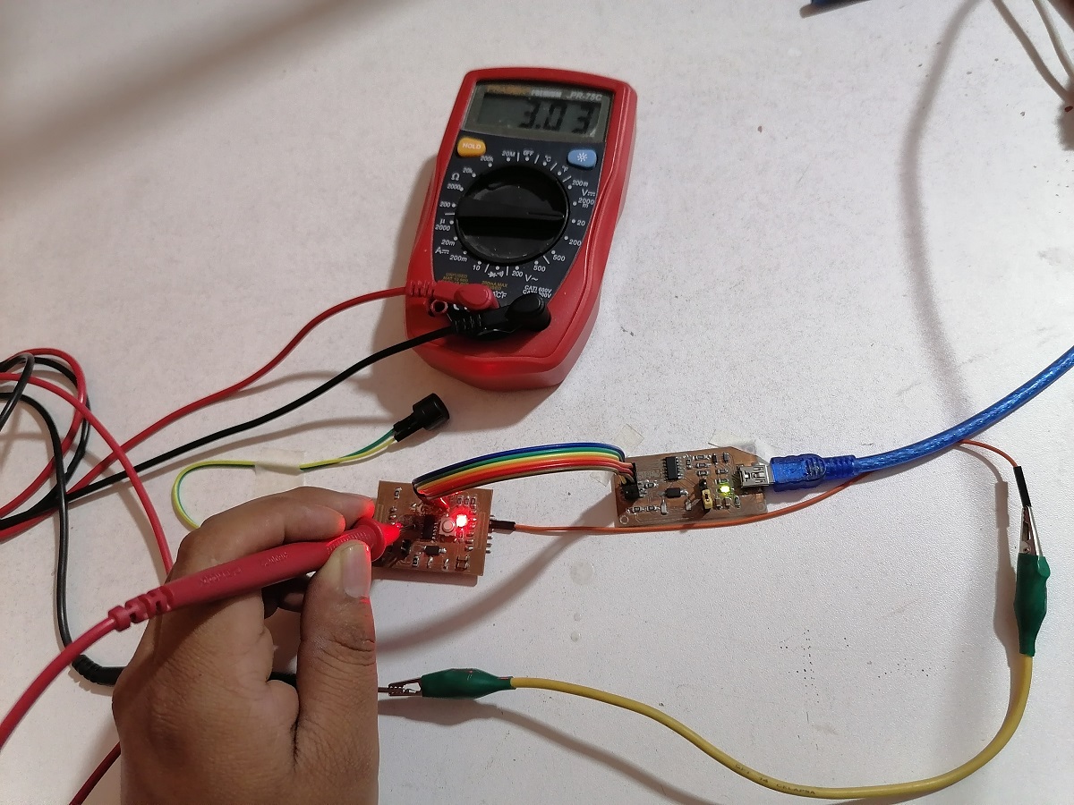
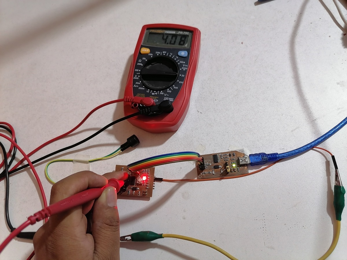
When I cover the incidence of the light with my finger, the voltage is an average of 4.08 Volts, since covering with my finger there is less illumination on the LDR:
But when we expose it to more light, the voltage drops to an average of 1.71 Volts, said voltage value is inversely proportional to the intensity of incidence of the light to the LDR
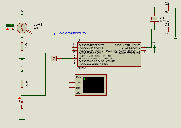
SIMULATION
Schematic of Sensor-Microcontroller-Actuator to probe som functionalities:
Write the program to simulate in Attiny44A:
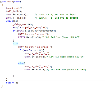
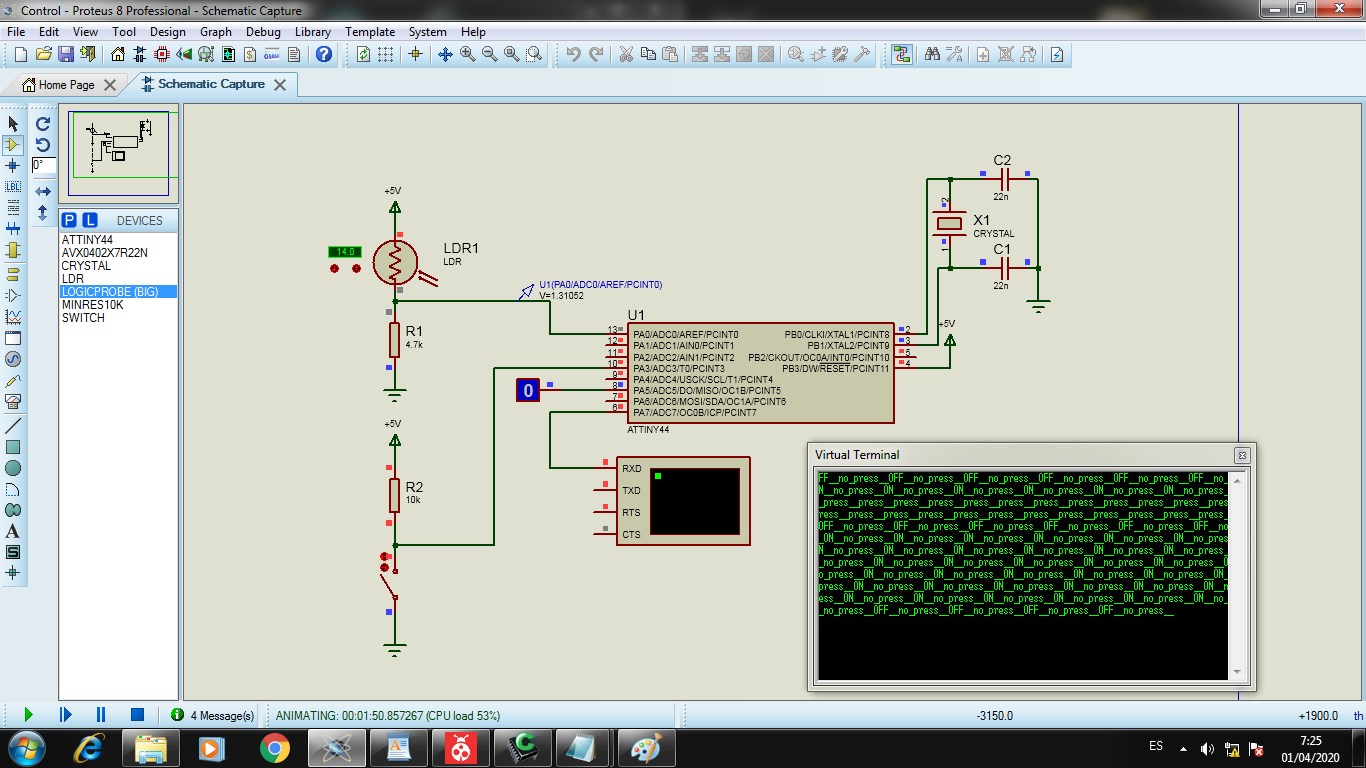
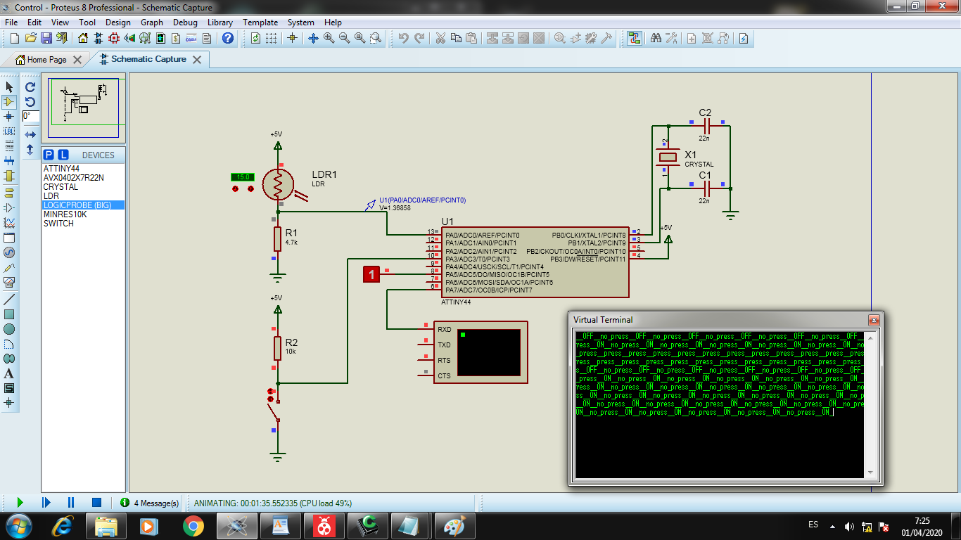
We can see simulating:
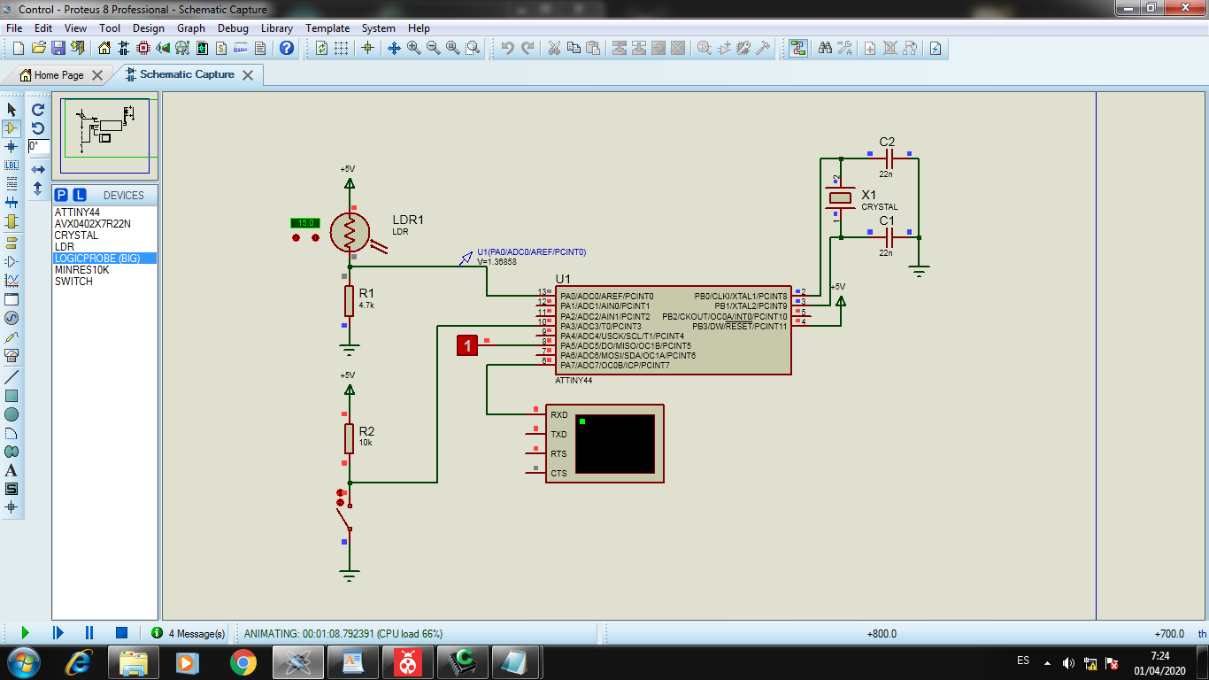
When the switch is PRESS the ADC Proccess is Disabled:
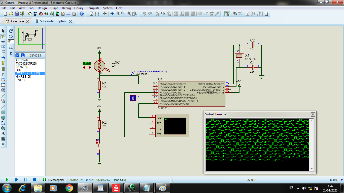
When the switch is RELEASE the ADC Proccess is Enabled but when the ADC is less to 278 units the LED is OFF:
When the switch is RELEASE the ADC Proccess is Enabled but when the ADC is greater then 278 units the LED is ON:
Designed Files
| Description | Files |
|---|---|
| IR Sensor Project | Tonos.ino |
| C++ Program | main.cpp |
| Hex Files | Input.hex |